Free Shipping on Equipment & Parts orders of $200 or more! * Click for Restrictions

Have a question? 800-440-6723 International: 803-252-0100

English Se habla español

Tennant M20 kit installation instructions

Tennant's instruction bulletins for M20 kits (60 bulletins, 435 pages): what each kit is for, what it fits, the safety warnings, the parts with prices, and every installation page with its text.‌‌​⁠‍‍‌​‌​‍‌⁠‌⁠​⁠‌‌⁠​​​​​​​​​​​‌​‍‌​​‌⁠‍‌‌⁠‌​‍​⁠⁠‌‌​‍​‌​​​‍⁠

Tennant part numbers changed. In November 2025 Tennant renumbered all of its parts. Every line here shows the new number and the old one, so an old printed manual still works: look up the old number and it takes you to the new one.

From Tennant's M20 instruction bulletins (2006–2024), 435 pages.
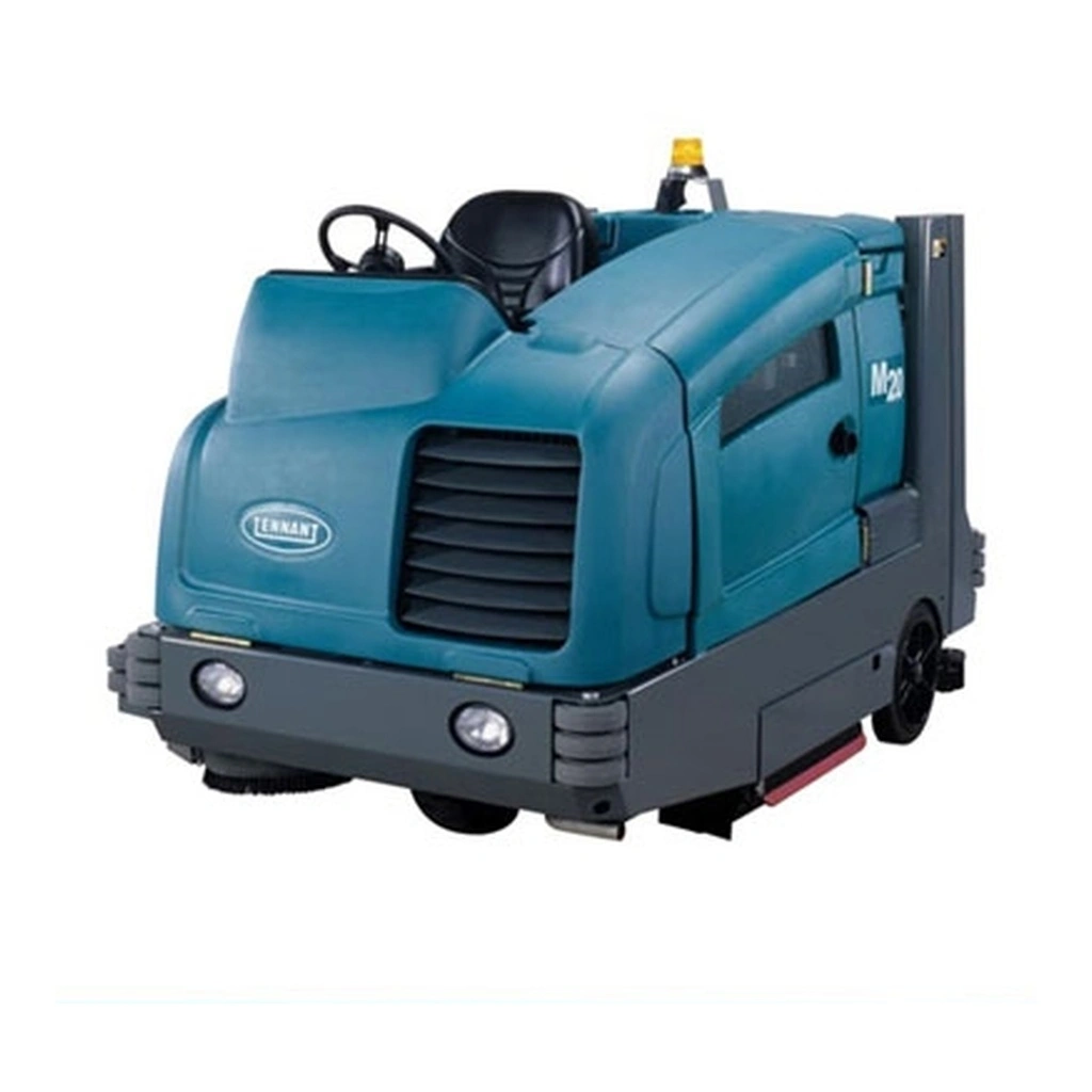
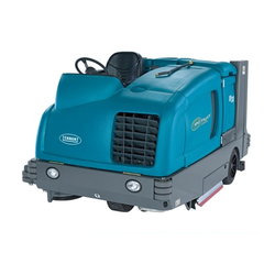
Tennant M20 rider sweeper-scrubber
Tennant M20 integrated sweeper-scrubber. Shop M20 machines
Machine
M20 rider sweeper-scrubber
Cleaning path
40 in (56 in with side brush)
Solution / recovery
56 / 73 gal
Hopper
3.9 ft³, 390 lb
Power
Gasoline, LPG or diesel
Main brushes
2 × 40 in cylindrical

How to read this list

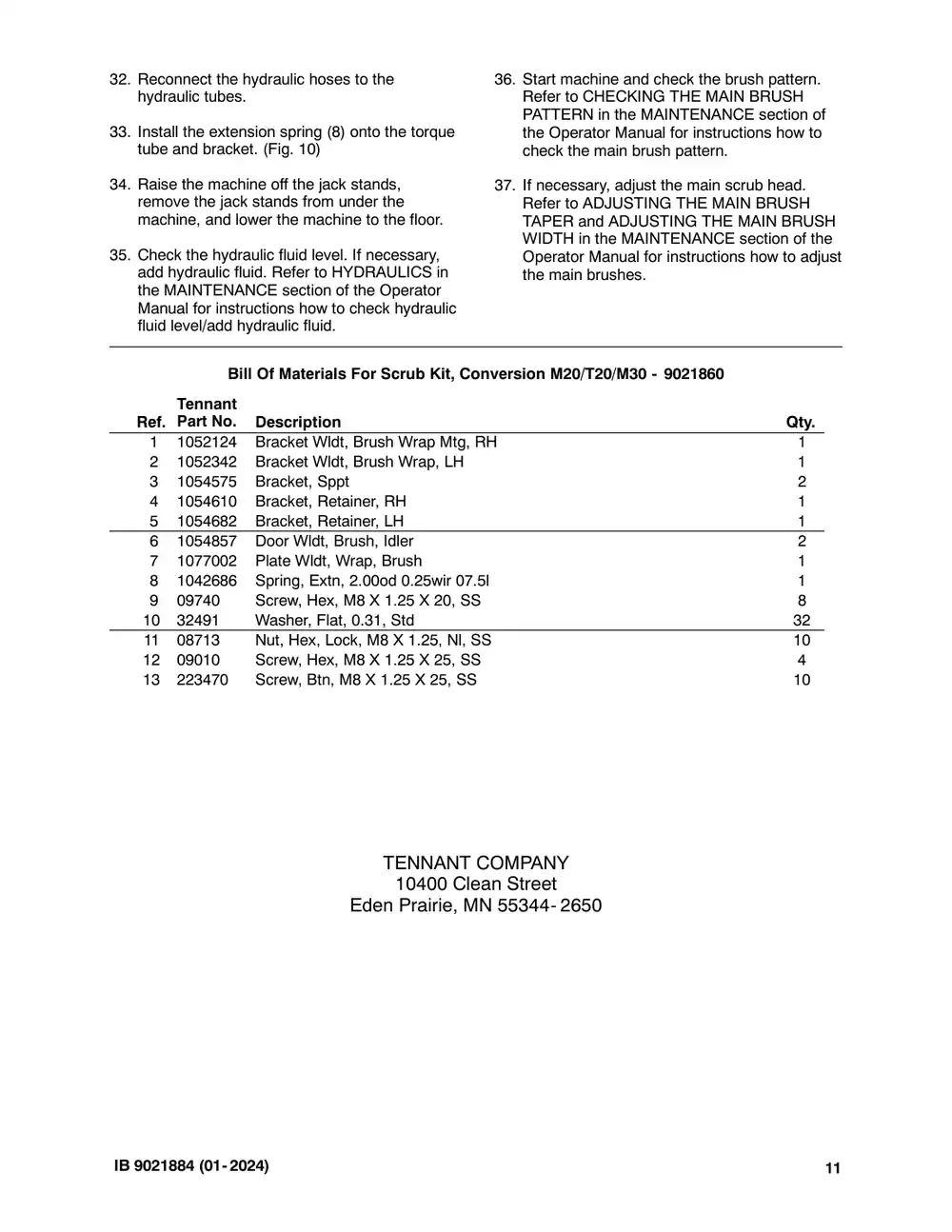
instructions how to check hydraulic fluid level/add hydraulic fluid. Bill Of Materials For Scrub Kit, Conversion M20/T20/M30

Tennant instruction bulletin 9021884 rev. 00Published 01-2024Kit 9021860

What it’s for: Replace the scrub head on M20/M30/T20 machines equipped with cylindrical scrub heads.

  • Machines: M20, M30, T20
  • M20: all
  • Power: gasoline, LPG and diesel
  • Applies to: cylindrical brushes

Time: 6- 7 hours · Special tools: NONE

Safety warnings (from the bulletin, word for word)

  • FOR SAFETY: Before leaving or servicing machine, stop on level surface, turn off machine, set parking brake, and remove key.
  • FOR SAFETY: When servicing machine, block machine tires before jacking machine up. Use a hoist or jack that will support the weight of the machine. Jack machine up at designated locations only. Support machine with jack stands.

Tennant says an authorized service provider should install this kit. SES is one: Have SES install this kit.

Parts

Parts for Tennant instruction bulletin 9021884
ItemPart numberQtyDescriptionPrice
TN4018398Old # 90218601instructions how to check hydraulic fluid level/add hydraulic fluid. Bill Of Materials For Scrub Kit, Conversion M20/T20/M30KitCall for availability 800-440-6723
1TN4040825Old # 10521241Bracket Wldt, Brush Wrap Mtg, RH$470.60/EA
2TN4041051Old # 10523421Bracket Wldt, Brush Wrap, LH$443.90/EA
3TN4038636Old # 10545752Bracket, Sppt$39.20/EA
4TN4038642Old # 10546101Bracket, Retainer, RH$18.60/EA
5TN4038661Old # 10546821Bracket, Retainer, LH$18.60/EA
6TN4038684Old # 10548572Door Wldt, Brush, Idler$205.40/EA
7TN4232148Old # 10770021Plate Wldt, Wrap, Brush$306.50/EA
8TN4044719Old # 10426861Spring, Extn, 2.00od 0.25wir 07.5l$23.40/EA
9TN4041992Old # 097408Screw, Hex, M8 X 1.25 X 20, SS$3.30/EA
10TN4034137Old # 3249132Washer, Flat, 0.31, Std$2.50/EA
11TN4041929Old # 0871310Nut, Hex, Lock, M8 X 1.25, Nl, SS$3.30/EA
12TN4041943Old # 090104Screw, Hex, M8 X 1.25 X 25, SS$3.30/EA
13TN4037712Old # 22347010Screw, Btn, M8 X 1.25 X 25, SS$4.00/EA

Bulletin PDF: Sign in to view or downloadSign in to download

Installation instructions (11 pages)
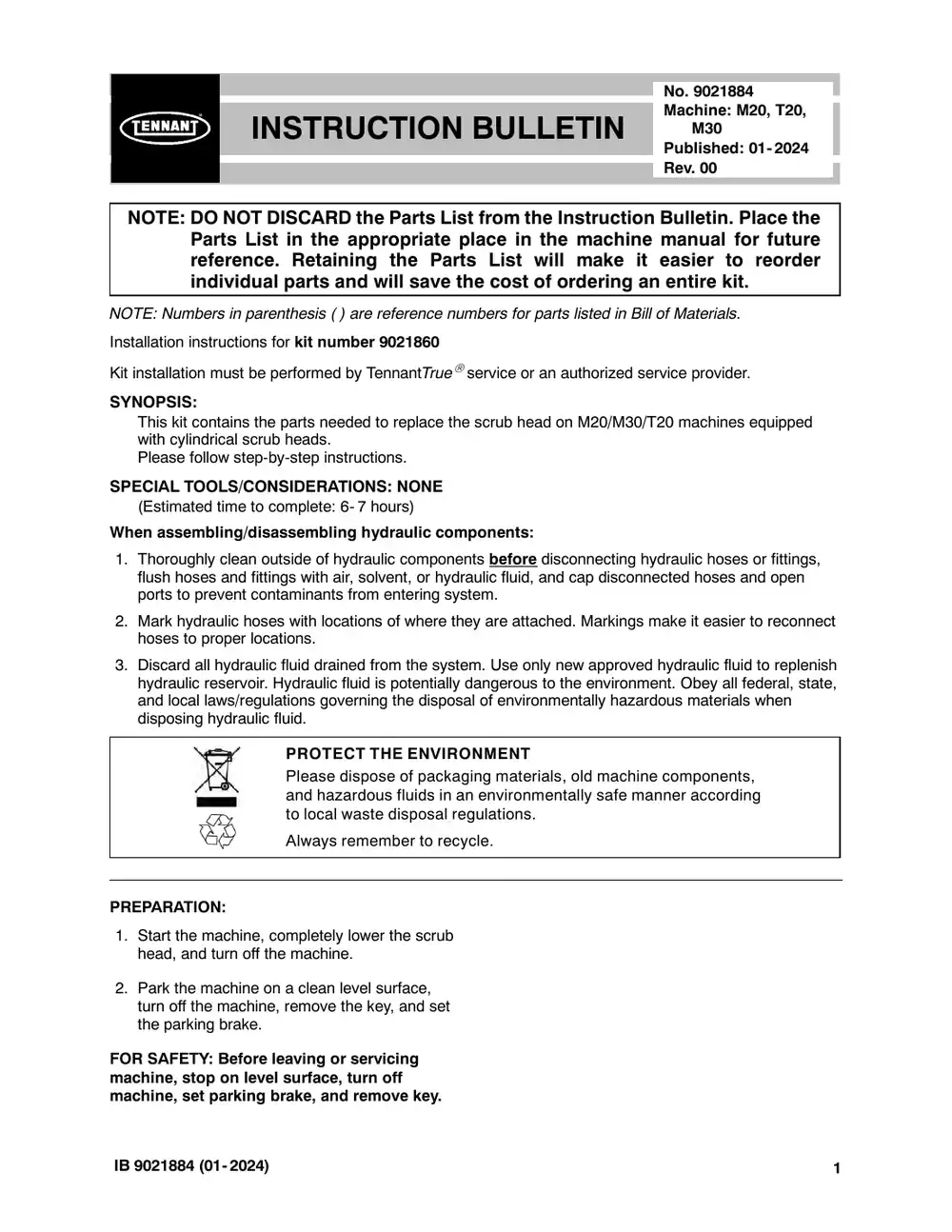
Tennant M20 instruction bulletin 9021884, page 1 of 11
Page 1 of 11 SES ref PF-PZ3X-QLN4‌‌​⁠‍‍‌​‌​‍‌⁠‌⁠​⁠‌‌⁠⁠⁠‌‍​​​‌​​​‌​‍‌​⁠​‍⁠‍​‌‍‌​‍‍​⁠​​⁠​​‍‌⁠‍‌
Text of this page
No. 9021884 Machine: M20, T20, INSTRUCTION BULLETIN M30 Published: 01- 2024 Rev. 00 NOTE: DO NOT DISCARD the Parts List from the Instruction Bulletin. Place the Parts List in the appropriate place in the machine manual for future reference. Retaining the Parts List will make it easier to reorder individual parts and will save the cost of ordering an entire kit. NOTE: Numbers in parenthesis ( ) are reference numbers for parts listed in Bill of Materials. Installation instructions for kit number TN4018398 Kit installation must be performed by TennantTrueservice or an authorized service provider. SYNOPSIS: This kit contains the parts needed to replace the scrub head on M20/M30/T20 machines equipped with cylindrical scrub heads. Please follow step-by-step instructions. SPECIAL TOOLS/CONSIDERATIONS: NONE (Estimated time to complete: 6- 7 hours) When assembling/disassembling hydraulic components: 1. Thoroughly clean outside of hydraulic components before disconnecting hydraulic hoses or fittings, flush hoses and fittings with air, solvent, or hydraulic fluid, and cap disconnected hoses and open ports to prevent contaminants from entering system. 2. Mark hydraulic hoses with locations of where they are attached. Markings make it easier to reconnect hoses to proper locations. 3. Discard all hydraulic fluid drained from the system. Use only new approved hydraulic fluid to replenish hydraulic reservoir. Hydraulic fluid is potentially dangerous to the environment. Obey all federal, state, and local laws/regulations governing the disposal of environmentally hazardous materials when disposing hydraulic fluid. PROTECT THE ENVIRONMENT Please dispose of packaging materials, old machine components, and hazardous fluids in an environmentally safe manner according to local waste disposal regulations. Always remember to recycle. PREPARATION: 1. Start the machine, completely lower the scrub head, and turn off the machine. 2. Park the machine on a clean level surface, turn off the machine, remove the key, and set the parking brake. FOR SAFETY: Before leaving or servicing machine, stop on level surface, turn off machine, set parking brake, and remove key. IB 9021884 (01- 2024) 1
Tennant M20 instruction bulletin 9021884, page 2 of 11
Page 2 of 11
Text of this page
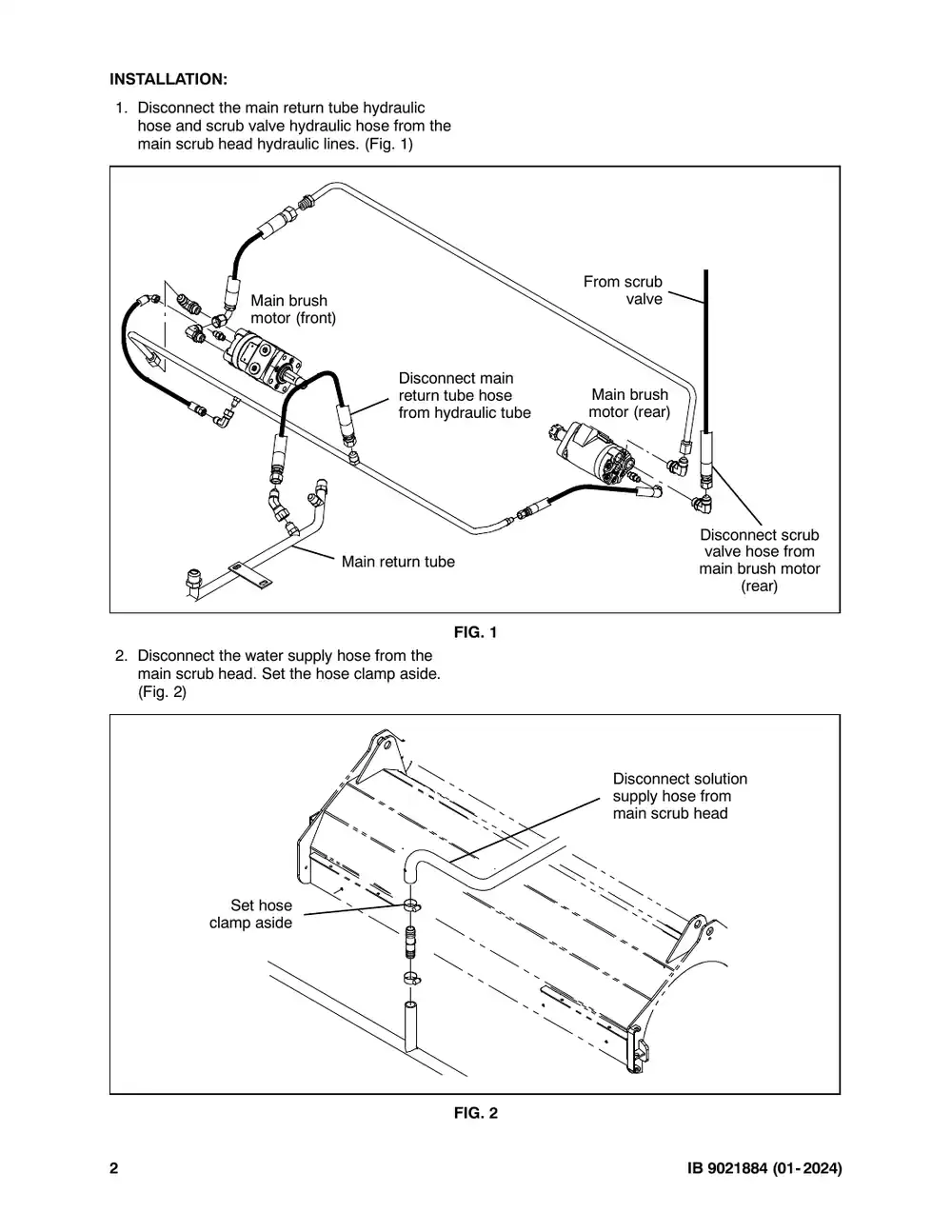
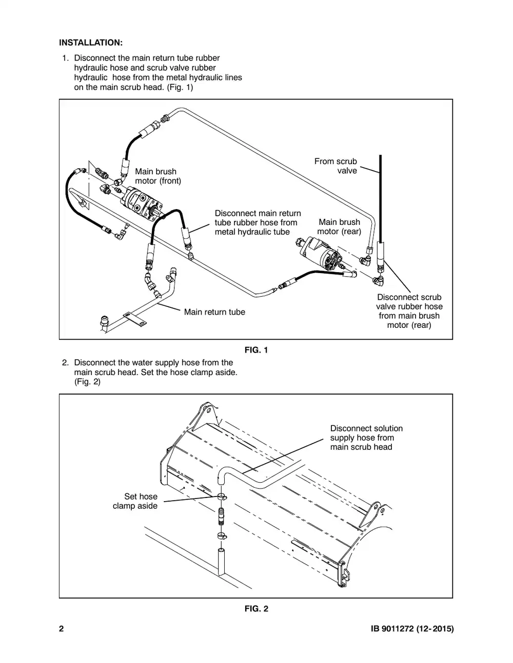
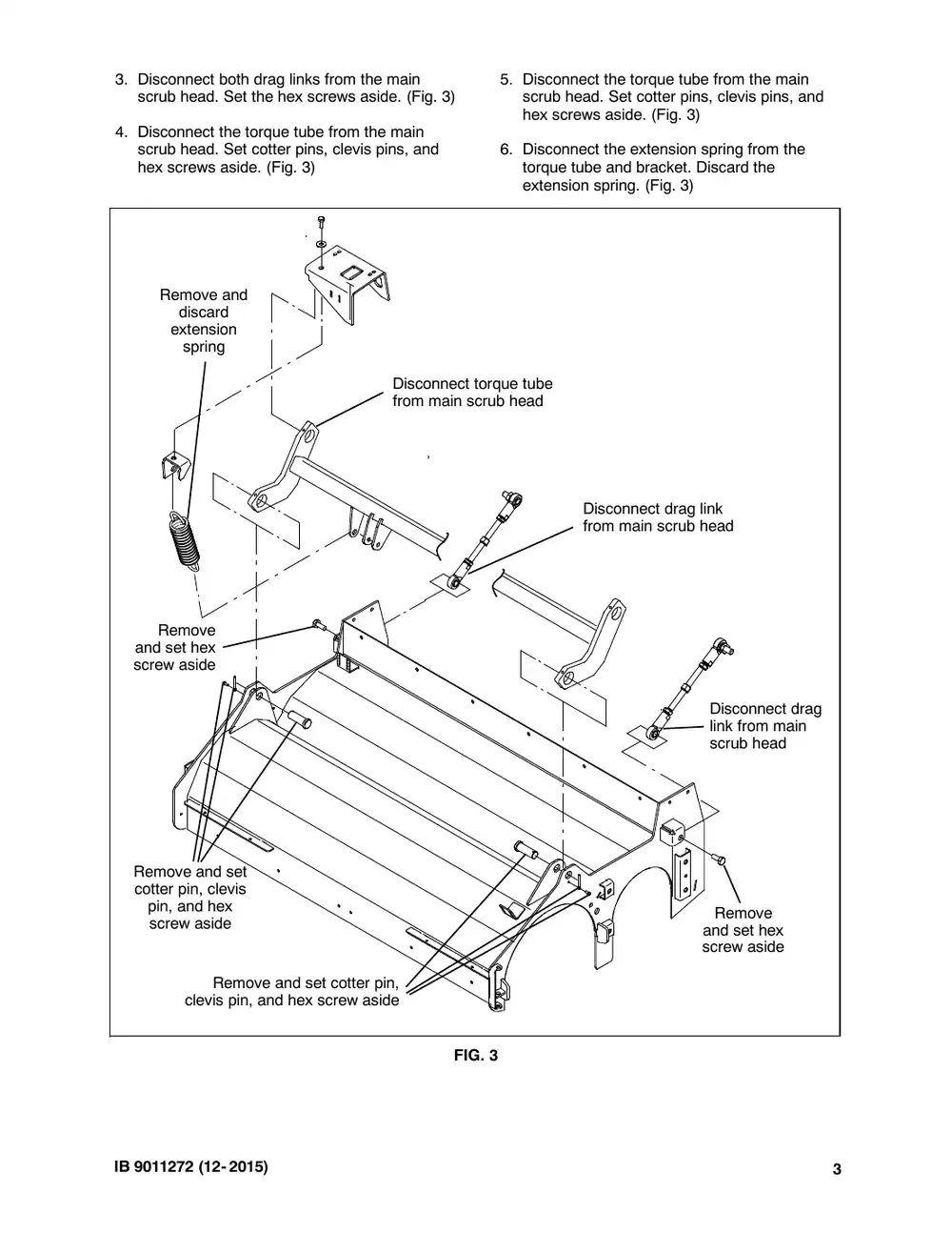
INSTALLATION: 1. Disconnect the main return tube hydraulic hose and scrub valve hydraulic hose from the main scrub head hydraulic lines. (Fig. 1) Main brush motor (front) Disconnect return tube from hydrau Main return tube FIG 2. Disconnect the water supply hose from the main scrub head. Set the hose clamp aside. (Fig. 2) Set hose clamp aside FIG 2 From scrub valve main hose Main brush ulic tube motor (rear) Disconnect scrub valve hose from main brush motor (rear) G. 1 Disconnect solution supply hose from main scrub head G. 2 IB 9021884 (01- 2024)
Tennant M20 instruction bulletin 9021884, page 3 of 11
Page 3 of 11
Text of this page
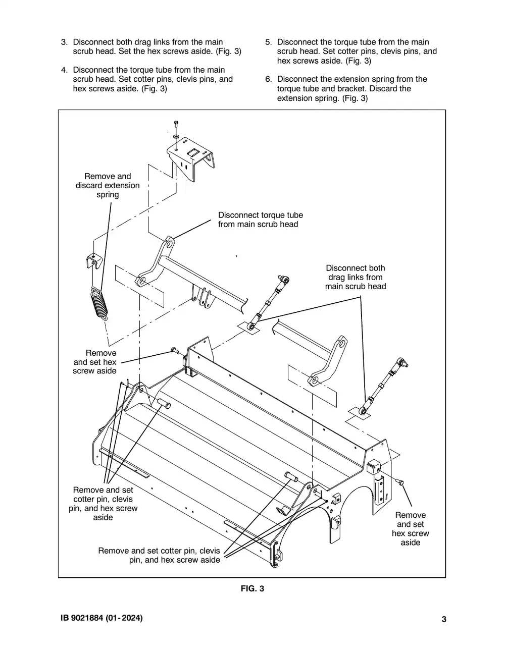
3. Disconnect both drag links from the main scrub head. Set the hex screws aside. (Fig. 3) 4. Disconnect the torque tube from the main scrub head. Set cotter pins, clevis pins, and hex screws aside. (Fig. 3) Remove and discard extension spring Disconnec from main Remove and set hex screw aside Remove and set cotter pin, clevis pin, and hex screw aside Remove and set cotter pin, clevis pin, and hex screw aside FIG IB 9021884 (01- 2024) 5. Disconnect the torque tube from the main scrub head. Set cotter pins, clevis pins, and hex screws aside. (Fig. 3) 6. Disconnect the extension spring from the torque tube and bracket. Discard the extension spring. (Fig. 3) ect torque tube n scrub head Disconnect both drag links from main scrub head Remove and set hex screw aside G. 3 3
Tennant M20 instruction bulletin 9021884, page 4 of 11
Page 4 of 11
Text of this page
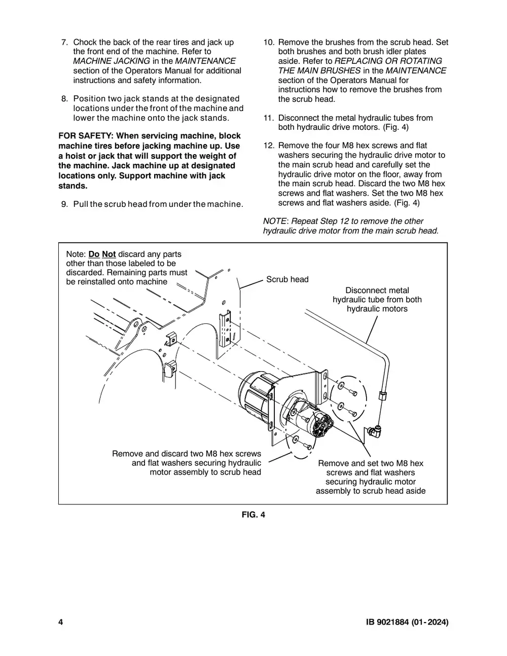
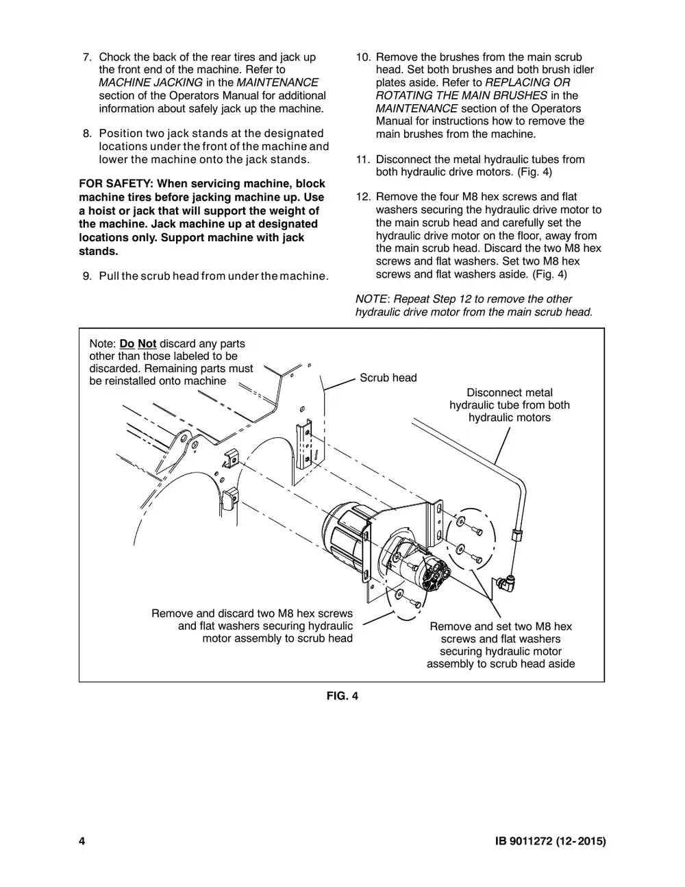
7. Chock the back of the rear tires and jack up the front end of the machine. Refer to MACHINE JACKING in the MAINTENANCE section of the Operators Manual for additional instructions and safety information. 8. Position two jack stands at the designated locations under the front of the machine and lower the machine onto the jack stands. FOR SAFETY: When servicing machine, block machine tires before jacking machine up. Use a hoist or jack that will support the weight of the machine. Jack machine up at designated locations only. Support machine with jack stands. 9. Pull the scrub head from under the machine. Note: Do Not discard any parts other than those labeled to be discarded. Remaining parts must be reinstalled onto machine Remove and discard two M8 hex screw and flat washers securing hydrau motor assembly to scrub hea FIG 4 10. Remove the brushes from the scrub head. Set both brushes and both brush idler plates aside. Refer to REPLACING OR ROTATING THE MAIN BRUSHES in the MAINTENANCE section of the Operators Manual for instructions how to remove the brushes from the scrub head. 11. Disconnect the metal hydraulic tubes from both hydraulic drive motors. (Fig. 4) 12. Remove the four M8 hex screws and flat washers securing the hydraulic drive motor to the main scrub head and carefully set the hydraulic drive motor on the floor, away from the main scrub head. Discard the two M8 hex screws and flat washers. Set the two M8 hex screws and flat washers aside. (Fig. 4) NOTE: Repeat Step 12 to remove the other hydraulic drive motor from the main scrub head. Scrub head Disconnect metal hydraulic tube from both hydraulic motors ws ulic Remove and set two M8 hex ad screws and flat washers securing hydraulic motor assembly to scrub head aside G. 4 IB 9021884 (01- 2024)
Tennant M20 instruction bulletin 9021884, page 5 of 11
Page 5 of 11
Text of this page
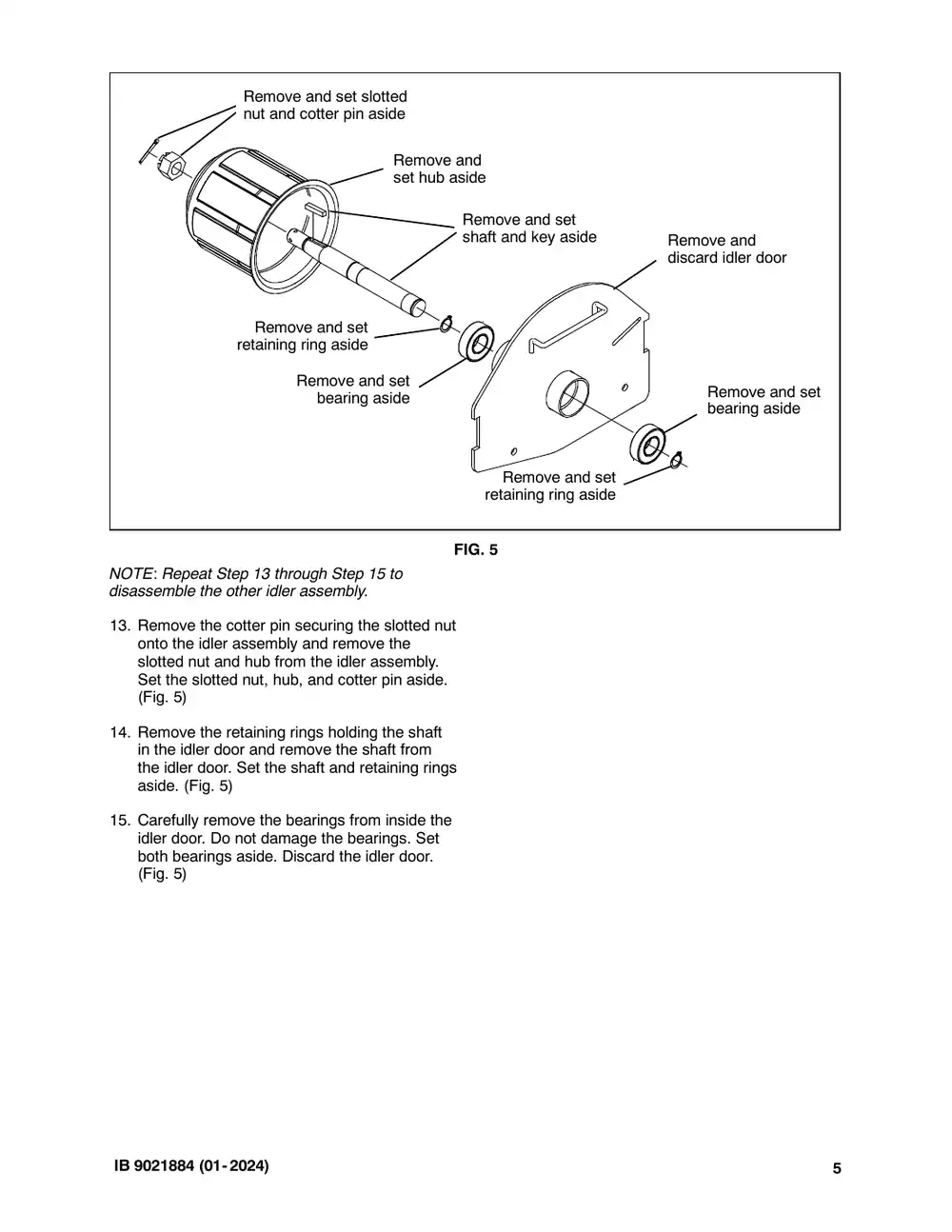
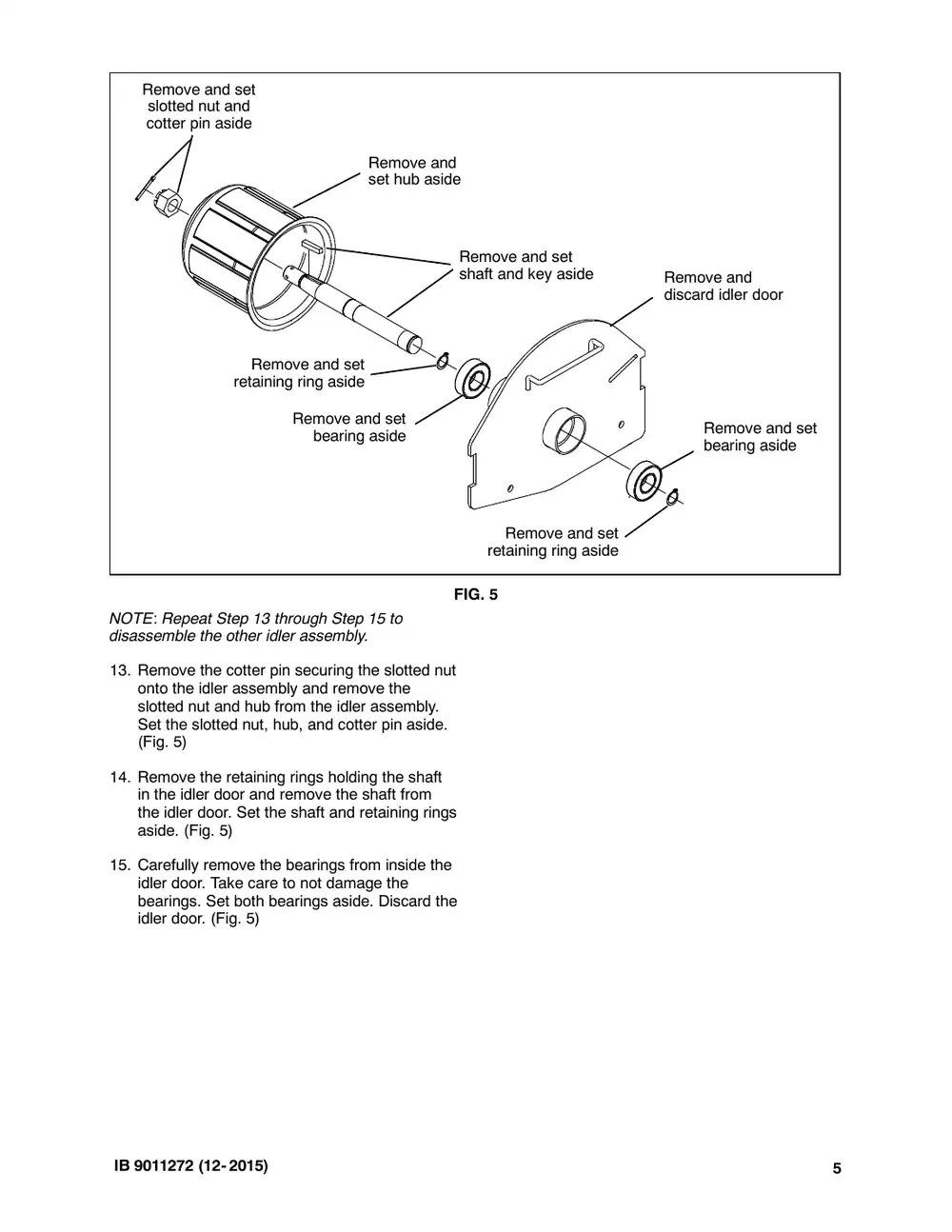
Remove and set slotted nut and cotter pin aside Remove and set hub aside Re sh Remove and set retaining ring aside Remove and set bearing aside FIG NOTE: Repeat Step 13 through Step 15 to disassemble the other idler assembly. 13. Remove the cotter pin securing the slotted nut onto the idler assembly and remove the slotted nut and hub from the idler assembly. Set the slotted nut, hub, and cotter pin aside. (Fig. 5) 14. Remove the retaining rings holding the shaft in the idler door and remove the shaft from the idler door. Set the shaft and retaining rings aside. (Fig. 5) 15. Carefully remove the bearings from inside the idler door. Do not damage the bearings. Set both bearings aside. Discard the idler door. (Fig. 5) IB 9021884 (01- 2024) emove and set haft and key aside Remove and discard idler door Remove and set bearing aside Remove and set retaining ring aside G. 5 5
Tennant M20 instruction bulletin 9021884, page 6 of 11
Page 6 of 11
Text of this page
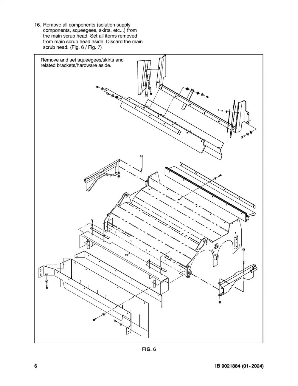
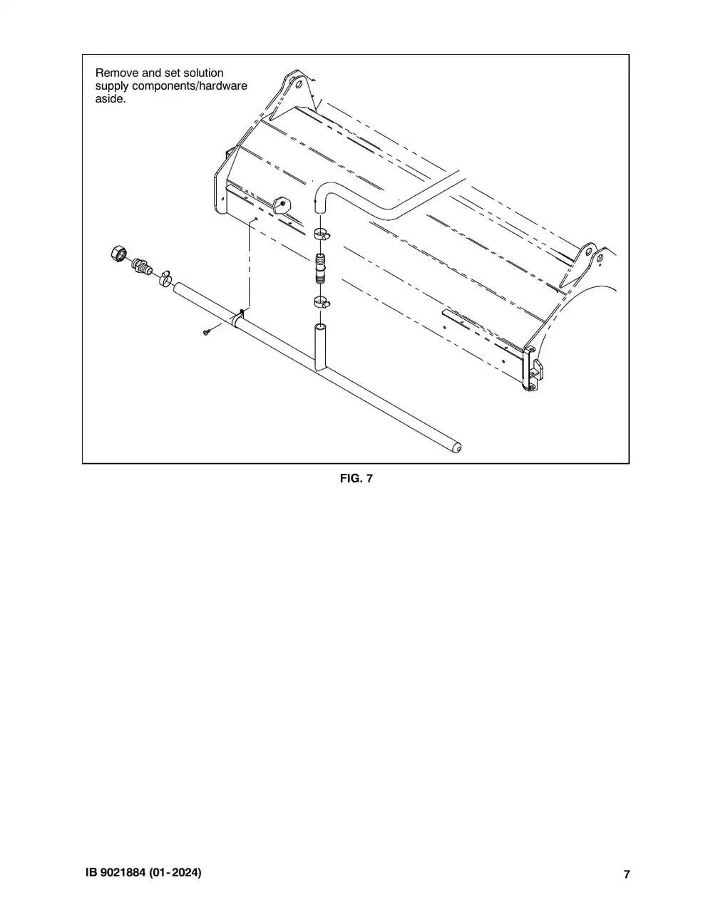
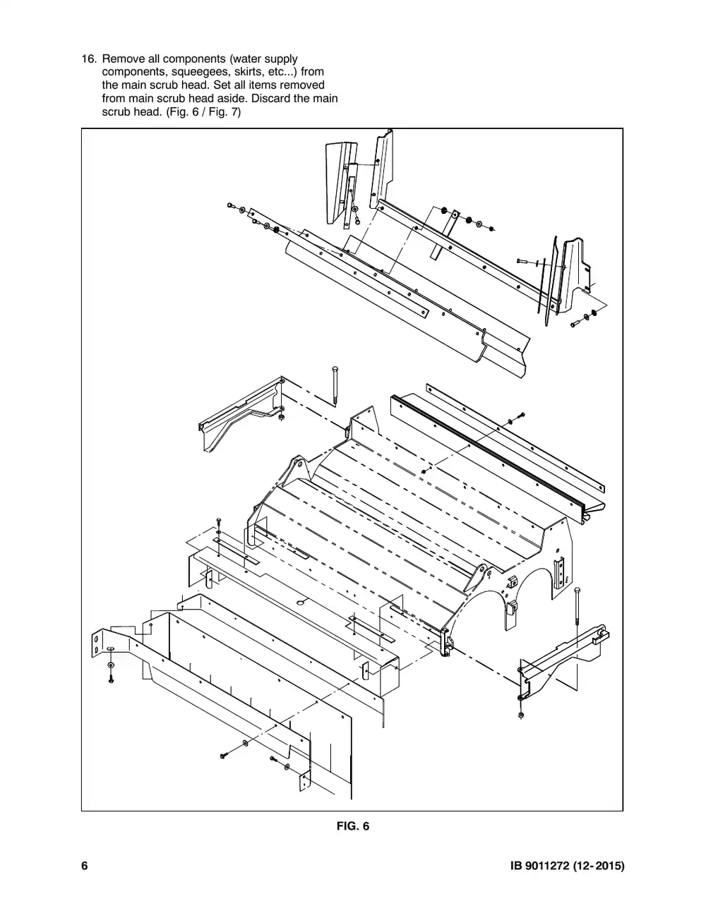
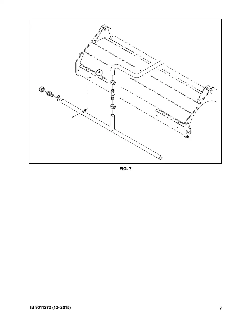
16. Remove all components (solution supply components, squeegees, skirts, etc...) from the main scrub head. Set all items removed from main scrub head aside. Discard the main scrub head. (Fig. 6 / Fig. 7) Remove and set squeegees/skirts and related brackets/hardware aside. FIG 6 G. 6 IB 9021884 (01- 2024)
Tennant M20 instruction bulletin 9021884, page 7 of 11
Page 7 of 11
Text of this page
Remove and set solution supply components/hardware aside. FIG. 7 IB 9021884 (01- 2024) 7
Tennant M20 instruction bulletin 9021884, page 8 of 11
Page 8 of 11
Text of this page
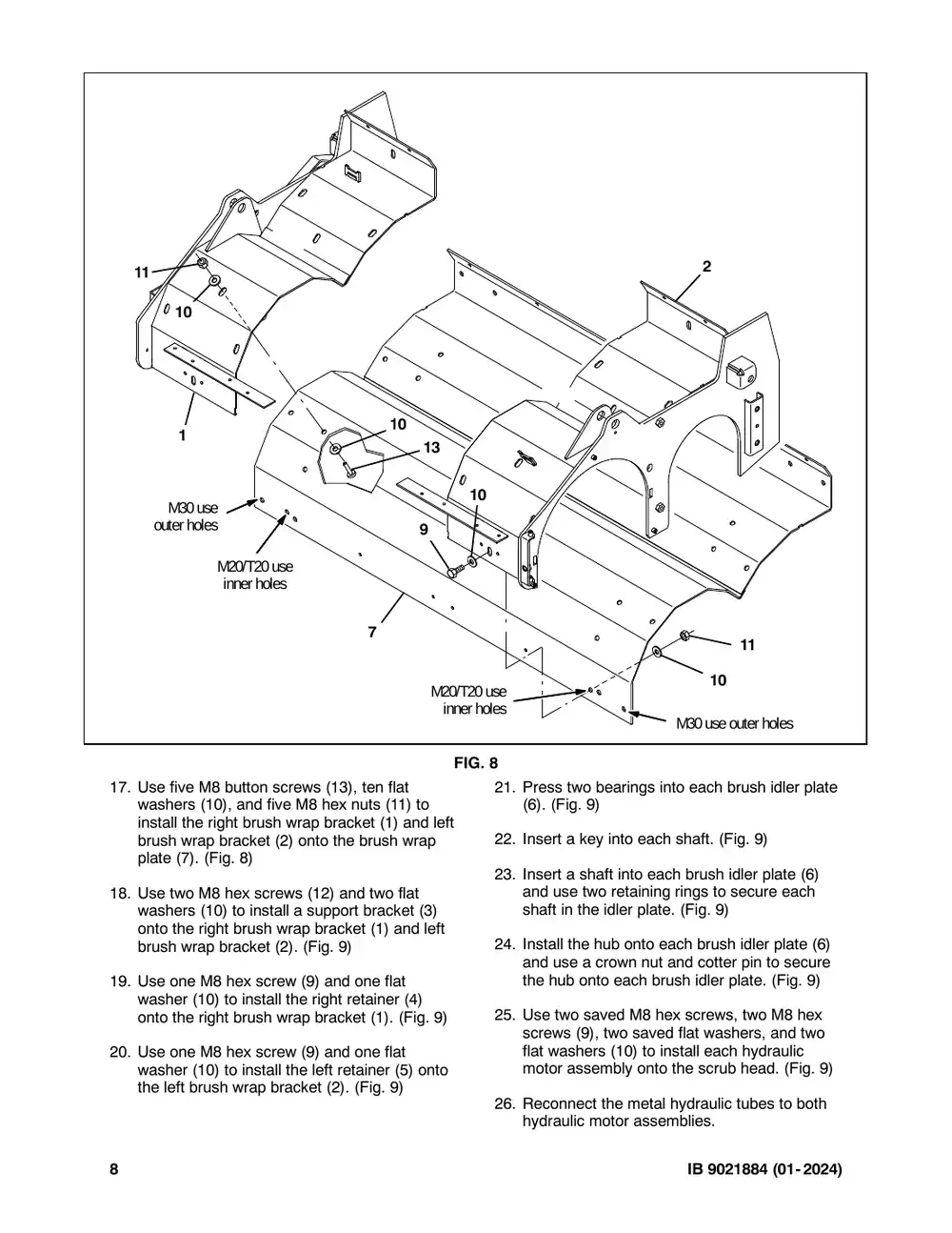
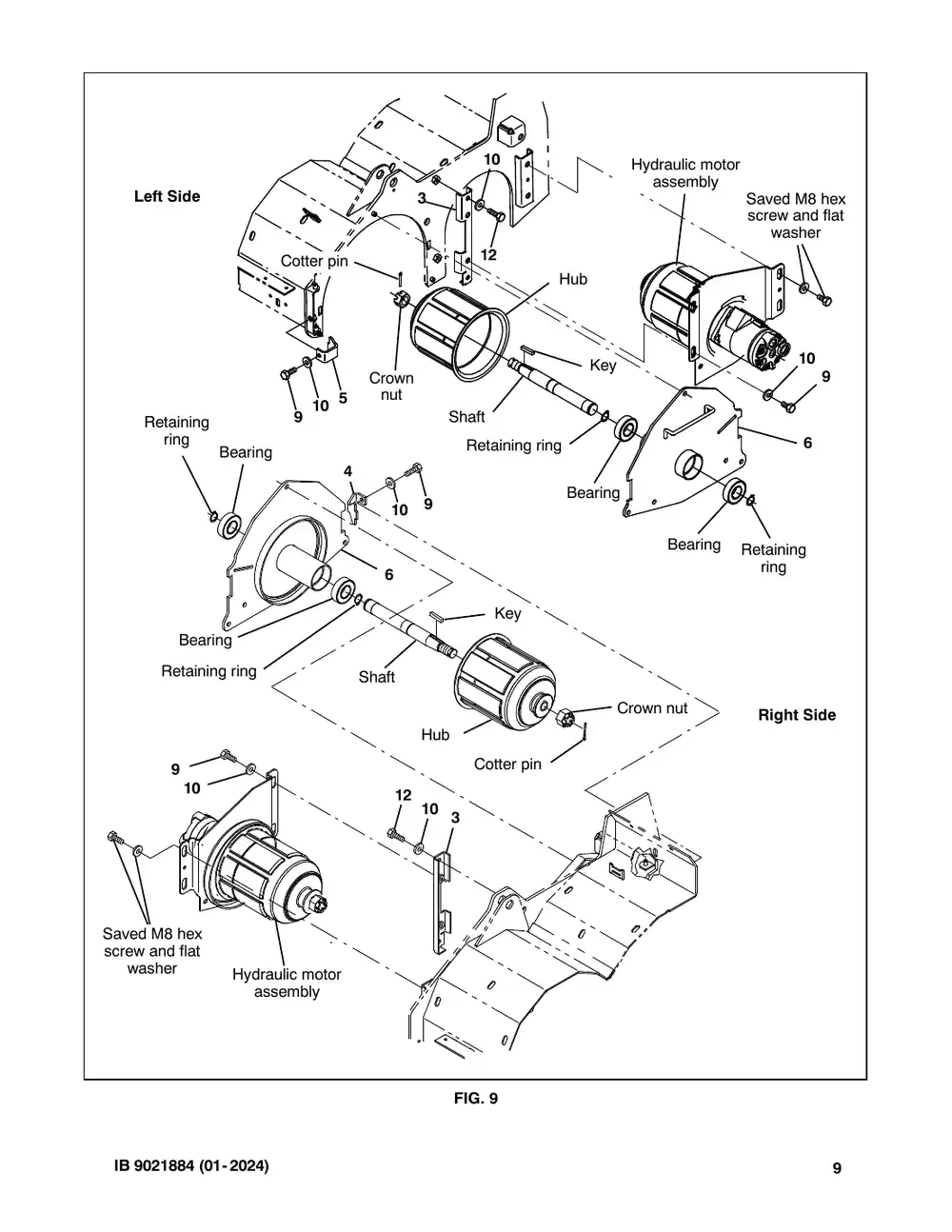
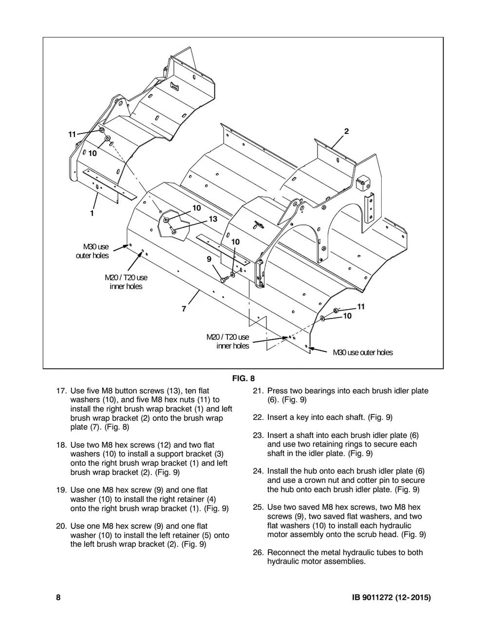
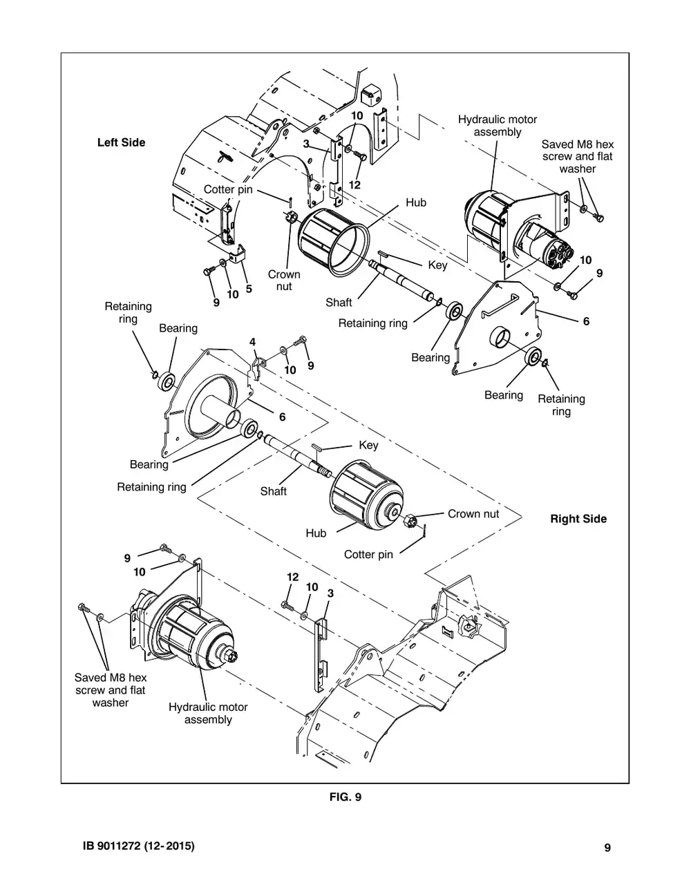
11 10 10 1 13 1 M30 use outer holes 9 M20/T20 use inner holes 7 M20/T20 inner h FIG 17. Use five M8 button screws (13), ten flat washers (10), and five M8 hex nuts (11) to install the right brush wrap bracket (1) and left brush wrap bracket (2) onto the brush wrap plate (7). (Fig. 8) 18. Use two M8 hex screws (12) and two flat washers (10) to install a support bracket (3) onto the right brush wrap bracket (1) and left brush wrap bracket (2). (Fig. 9) 19. Use one M8 hex screw (9) and one flat washer (10) to install the right retainer (4) onto the right brush wrap bracket (1). (Fig. 9) 20. Use one M8 hex screw (9) and one flat washer (10) to install the left retainer (5) onto the left brush wrap bracket (2). (Fig. 9) 8 2 10 11 10 0 use holes M30 use outer holes G. 8 21. Press two bearings into each brush idler plate (6). (Fig. 9) 22. Insert a key into each shaft. (Fig. 9) 23. Insert a shaft into each brush idler plate (6) and use two retaining rings to secure each shaft in the idler plate. (Fig. 9) 24. Install the hub onto each brush idler plate (6) and use a crown nut and cotter pin to secure the hub onto each brush idler plate. (Fig. 9) 25. Use two saved M8 hex screws, two M8 hex screws (9), two saved flat washers, and two flat washers (10) to install each hydraulic motor assembly onto the scrub head. (Fig. 9) 26. Reconnect the metal hydraulic tubes to both hydraulic motor assemblies. IB 9021884 (01- 2024)
Tennant M20 instruction bulletin 9021884, page 9 of 11
Page 9 of 11
Text of this page
Left Side 3 Cotter pin Crown 5 nut 10 9 Sha Retaining ring R Bearing 4 9 10 6 Bearing Retaining ring Shaft Hub C 9 10 12 10 3 Saved M8 hex screw and flat washer Hydraulic motor assembly FIG IB 9021884 (01- 2024) 10 Hydraulic motor assembly Saved M8 hex screw and flat washer 12 Hub 10 Key 9 aft Retaining ring 6 Bearing Bearing Retaining ring Key Crown nut Right Side Cotter pin G. 9 9
Tennant M20 instruction bulletin 9021884, page 10 of 11
Page 10 of 11
Text of this page
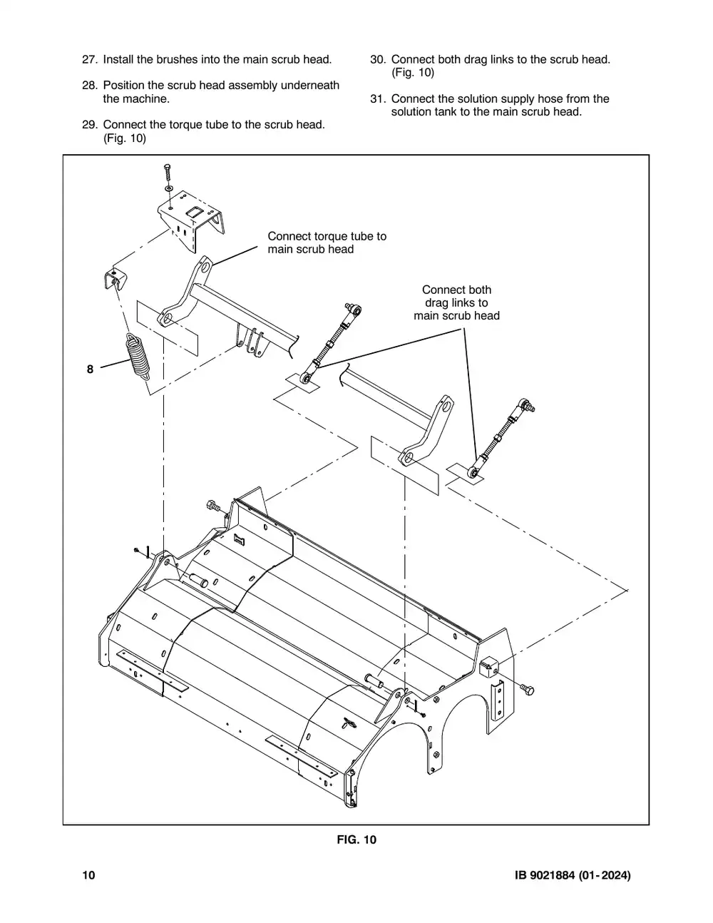
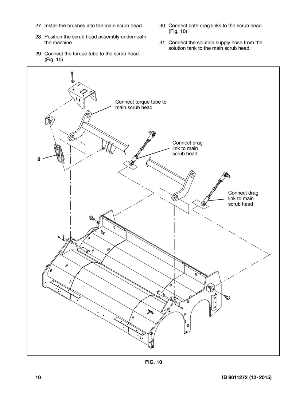
27. Install the brushes into the main scrub head. 28. Position the scrub head assembly underneath the machine. 29. Connect the torque tube to the scrub head. (Fig. 10) Connect torque tu main scrub head 8 FIG 10 30. Connect both drag links to the scrub head. (Fig. 10) 31. Connect the solution supply hose from the solution tank to the main scrub head. ube to Connect both drag links to main scrub head G. 10 IB 9021884 (01- 2024)
Tennant M20 instruction bulletin 9021884, page 11 of 11
Page 11 of 11
Text of this page
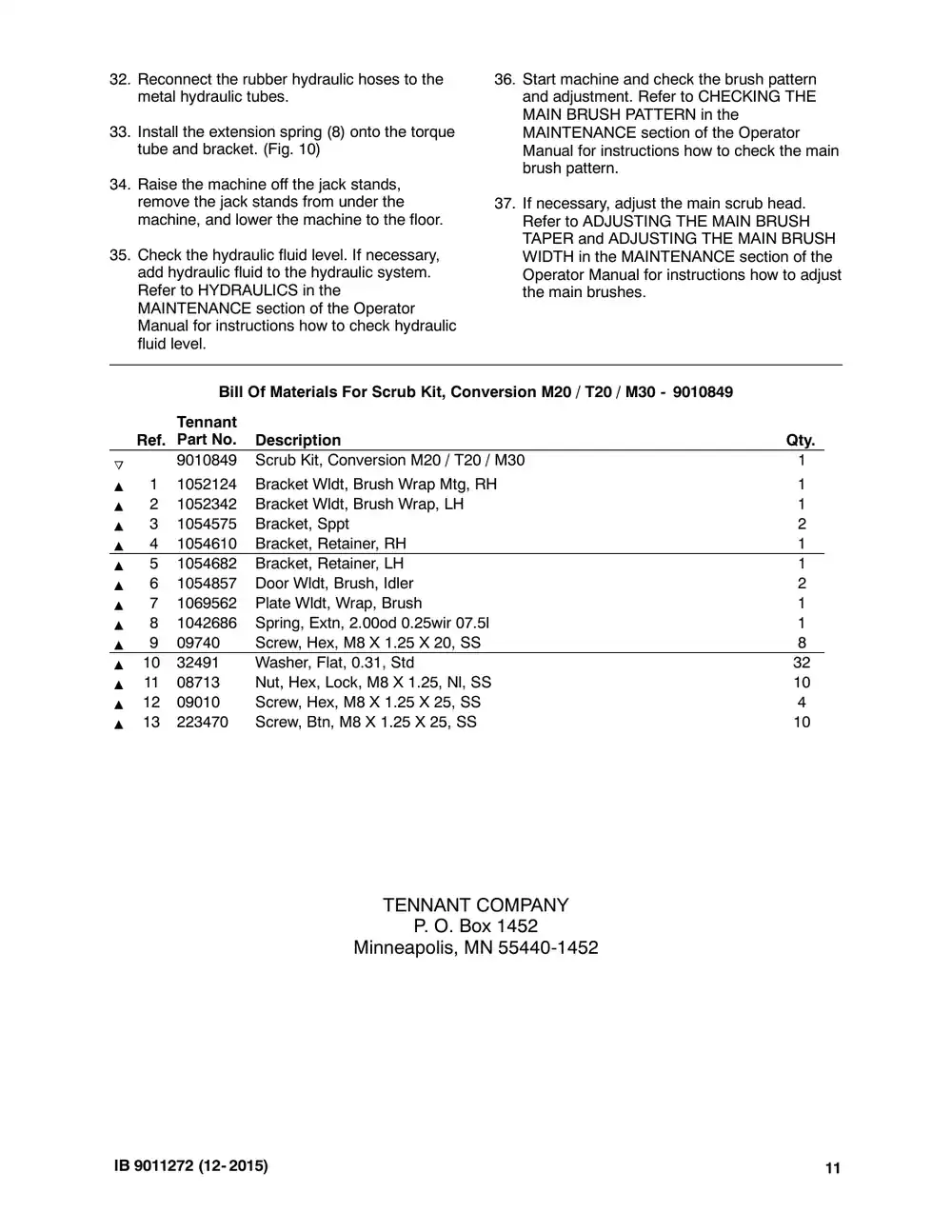
32. Reconnect the hydraulic hoses to the hydraulic tubes. 33. Install the extension spring (8) onto the torque tube and bracket. (Fig. 10) 34. Raise the machine off the jack stands, remove the jack stands from under the machine, and lower the machine to the floor. 35. Check the hydraulic fluid level. If necessary, add hydraulic fluid. Refer to HYDRAULICS in the MAINTENANCE section of the Operator Manual for instructions how to check hydraulic fluid level/add hydraulic fluid. Bill Of Materials For Scrub Kit, Co Tennant Ref. Part No. Description 1 TN4040825 Bracket Wldt, Brush Wrap Mtg, R 2 TN4041051 Bracket Wldt, Brush Wrap, LH 3 TN4038636 Bracket, Sppt 4 TN4038642 Bracket, Retainer, RH 5 TN4038661 Bracket, Retainer, LH 6 TN4038684 Door Wldt, Brush, Idler 7 TN4232148 Plate Wldt, Wrap, Brush 8 TN4044719 Spring, Extn, 2.00od 0.25wir 07. 9 TN4041992 Screw, Hex, M8 X 1.25 X 20, SS 10 TN4034137 Washer, Flat, 0.31, Std 11 TN4041929 Nut, Hex, Lock, M8 X 1.25, Nl, S 12 TN4041943 Screw, Hex, M8 X 1.25 X 25, SS 13 TN4037712 Screw, Btn, M8 X 1.25 X 25, SS TENNANT 10400 Cle Eden Prairie, M IB 9021884 (01- 2024) 36. Start machine and check the brush pattern. Refer to CHECKING THE MAIN BRUSH PATTERN in the MAINTENANCE section of the Operator Manual for instructions how to check the main brush pattern. 37. If necessary, adjust the main scrub head. Refer to ADJUSTING THE MAIN BRUSH TAPER and ADJUSTING THE MAIN BRUSH WIDTH in the MAINTENANCE section of the Operator Manual for instructions how to adjust the main brushes. onversion M20/T20/M30 - TN4018398 Qty. RH 1 1 2 1 1 2 1 .5l 1 S 8 32 SS 10 S 4 S 10 COMPANY ean Street MN 55344- 2650 11

Electrode Kit, 5 Plate, Hi Flow, Replmt

Tennant instruction bulletin 9018398 rev. 00Published 01-2024Kit 9018397

What it’s for: Replace the ec- H2O electrode plate on T3, T5, T7, 5680, T20, T17, T16, T15, and T12 scrubbers and M17, M20, and M30 sweeper- scrubbers.

  • Machines: M17, M20, M30, T12, T15, T16, T17, T20
  • M20: all
  • Power: gasoline, LPG and diesel
  • Applies to: ec-H2O

Time: 1- 2 hours · Special tools: NONE

Safety warnings (from the bulletin, word for word)

  • FOR SAFETY: Before leaving or servicing machine, stop on level surface, turn off machine, and remove key.
  • WARNING: Always disconnect battery cables from machine before working on electrical components.

Tennant says an authorized service provider should install this kit. SES is one: Have SES install this kit.

Parts

Parts for Tennant instruction bulletin 9018398
ItemPart numberQtyDescriptionPrice
TN4020962Old # 90183971Electrode Kit, 5 Plate, Hi Flow, ReplmtKitCall for availability 800-440-6723
1TN4034288Old # 12435701Hose, Molded, BM08/BM05Call for availability 800-440-6723
2TN4032414Old # 12592551Electrode, 5 Plate [De Nora]Call for availability 800-440-6723
3TN4040768Old # 10512661Hose, PVC, Brd, 0.31id 0.53od, Bulk, Clr (0.854 ft)Call for availability 800-440-6723
4TN4015366Old # 543332Clamp, Hose, Worm Drive, 0.31- 0.88d, .31w$5.10/EA
5TN4033062Old # 12350661Bracket, Clamp, Electrode, Front [WS] - Module 1060516 OnlyCall for availability 800-440-6723
6TN4033367Old # 12370361Plate, Mtg, Back - Module 1060516 OnlyCall for availability 800-440-6723
7TN4011910Old # 7631161Tie, Cable, Nyl, 15.3l .25w 4.50d Max - Module 1060516 Only$3.40/EA

Bulletin PDF: Sign in to view or downloadSign in to download

Installation instructions (8 pages)
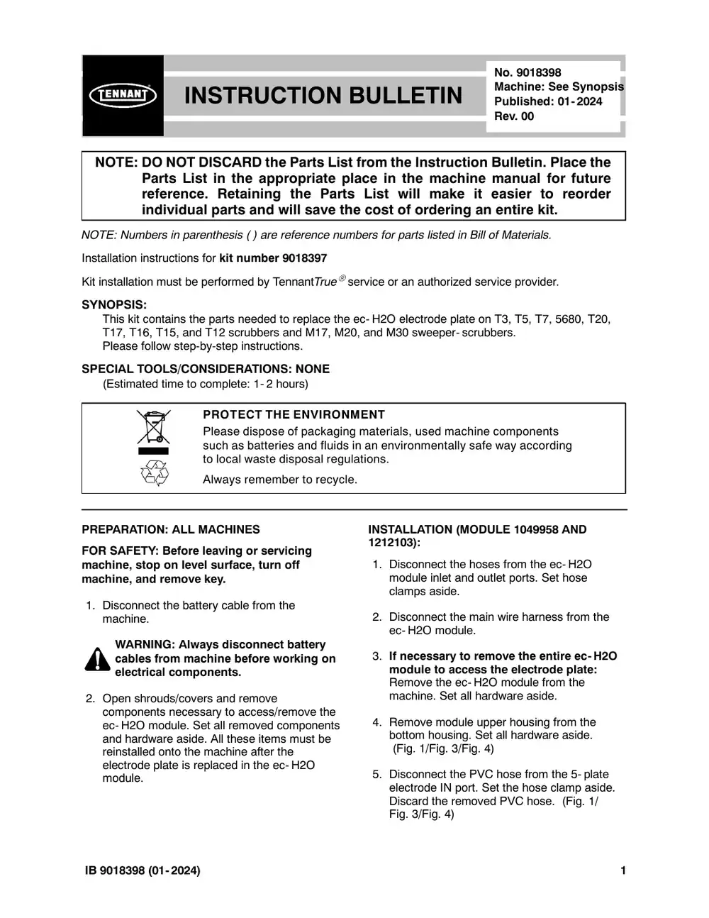
Tennant M20 instruction bulletin 9018398, page 1 of 8
Page 1 of 8 SES ref PF-QAGV-P2PG‌‌​⁠‍‍‌​‌​‍‌⁠‌⁠​⁠‌‌⁠‌‌​‌⁠‌​​​​​‌​‍‌​‌‍‍‍⁠⁠‌⁠​‍⁠​⁠‌‌​‌‌‍​⁠⁠‍‌
Text of this page
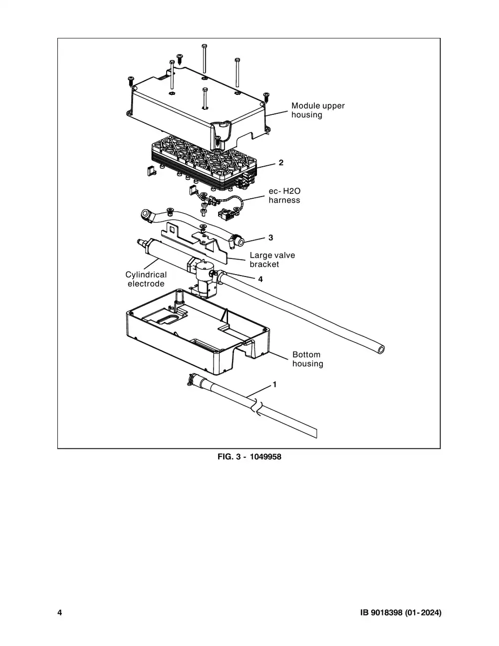
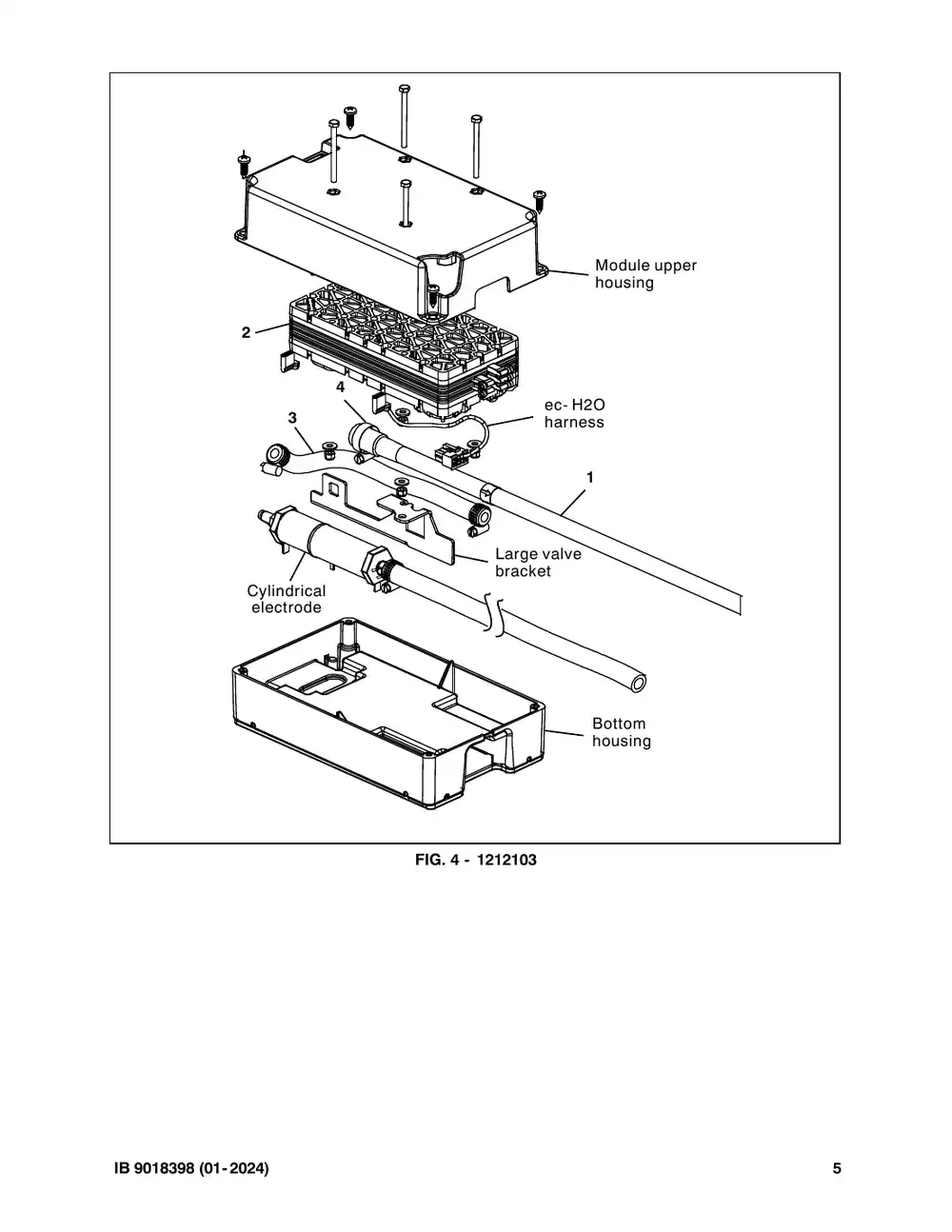
INSTRUCTION B NOTE: DO NOT DISCARD the Parts List Parts List in the appropriate pla reference. Retaining the Parts individual parts and will save the NOTE: Numbers in parenthesis ( ) are reference num Installation instructions for kit number TN4020962 Kit installation must be performed by TennantTruese SYNOPSIS: This kit contains the parts needed to replace the e T17, T16, T15, and T12 scrubbers and M17, M20 Please follow step-by-step instructions. SPECIAL TOOLS/CONSIDERATIONS: NONE (Estimated time to complete: 1- 2 hours) PROTECT THE ENVIRONM Please dispose of packaging such as batteries and fluids i to local waste disposal regula Always remember to recycle. PREPARATION: ALL MACHINES FOR SAFETY: Before leaving or servicing machine, stop on level surface, turn off machine, and remove key. 1. Disconnect the battery cable from the machine. WARNING: Always disconnect battery cables from machine before working on electrical components. 2. Open shrouds/covers and remove components necessary to access/remove the ec- H2O module. Set all removed components and hardware aside. All these items must be reinstalled onto the machine after the electrode plate is replaced in the ec- H2O module. IB 9018398 (01- 2024) No. 9018398 Machine: See Synopsis BULLETIN Published: 01- 2024 Rev. 00 from the Instruction Bulletin. Place the ace in the machine manual for future s List will make it easier to reorder e cost of ordering an entire kit. mbers for parts listed in Bill of Materials. ervice or an authorized service provider. ec- H2O electrode plate on T3, T5, T7, 5680, T20, 0, and M30 sweeper- scrubbers. MENT g materials, used machine components in an environmentally safe way according ations. . INSTALLATION (MODULE 1049958 AND 1212103): 1. Disconnect the hoses from the ec- H2O module inlet and outlet ports. Set hose clamps aside. 2. Disconnect the main wire harness from the ec- H2O module. 3. If necessary to remove the entire ec- H2O module to access the electrode plate: Remove the ec- H2O module from the machine. Set all hardware aside. 4. Remove module upper housing from the bottom housing. Set all hardware aside. (Fig. 1/Fig. 3/Fig. 4) 5. Disconnect the PVC hose from the 5- plate electrode IN port. Set the hose clamp aside. Discard the removed PVC hose. (Fig. 1/ Fig. 3/Fig. 4) 1
Tennant M20 instruction bulletin 9018398, page 2 of 8
Page 2 of 8
Text of this page
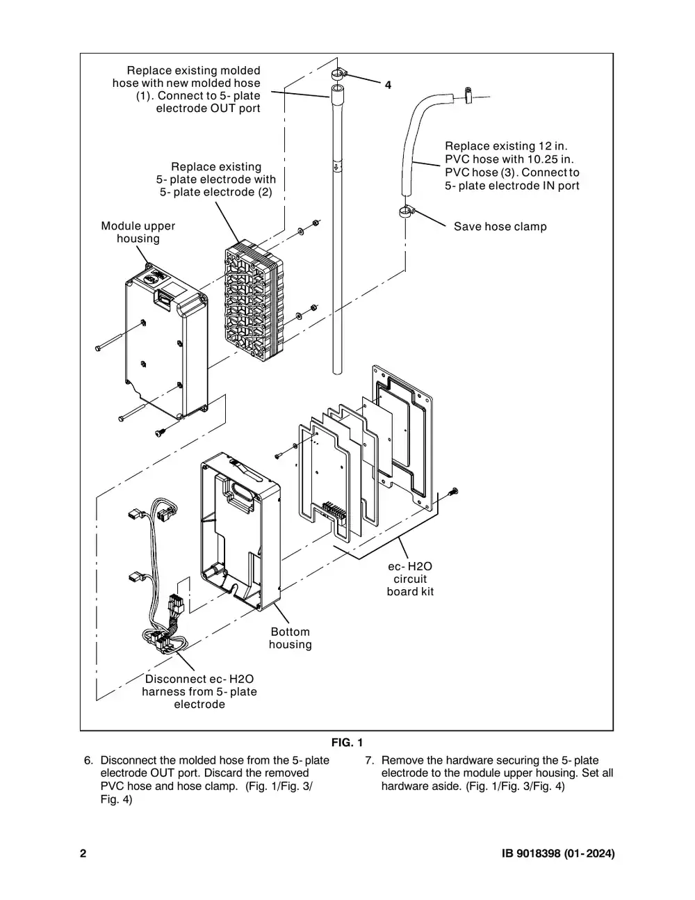
Replace existing molded hose with new molded hose hose with new molded hose (1). Connect to 5- plate electrode OUT port Replace existing 5- plate electrode with 5- plate electrode (2) Module upper housing Bottom housing Disconnect ec- H2O harness from 5- plate electrode FIG 6. Disconnect the molded hose from the 5- plate electrode OUT port. Discard the removed PVC hose and hose clamp. (Fig. 1/Fig. 3/ Fig. 4) 2 4 Replace existing 12 in. PVC hose with 10.25 in. PVC hose (3). Connect to 5- plate electrode IN port Save hose clamp ec- H2O circuit board kit G. 1 7. Remove the hardware securing the 5- plate electrode to the module upper housing. Set all hardware aside. (Fig. 1/Fig. 3/Fig. 4) IB 9018398 (01- 2024)
Tennant M20 instruction bulletin 9018398, page 3 of 8
Page 3 of 8
Text of this page
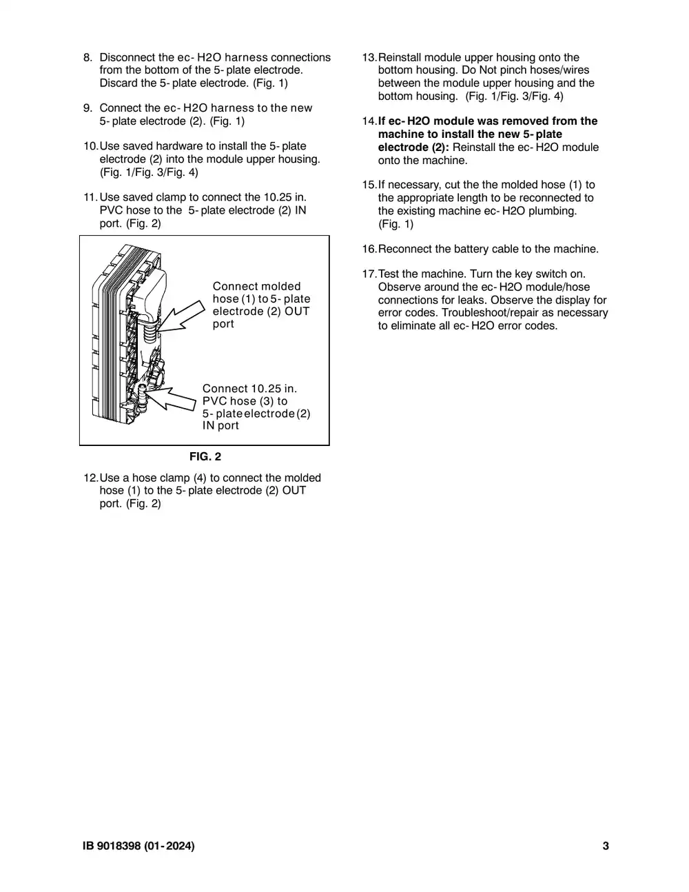
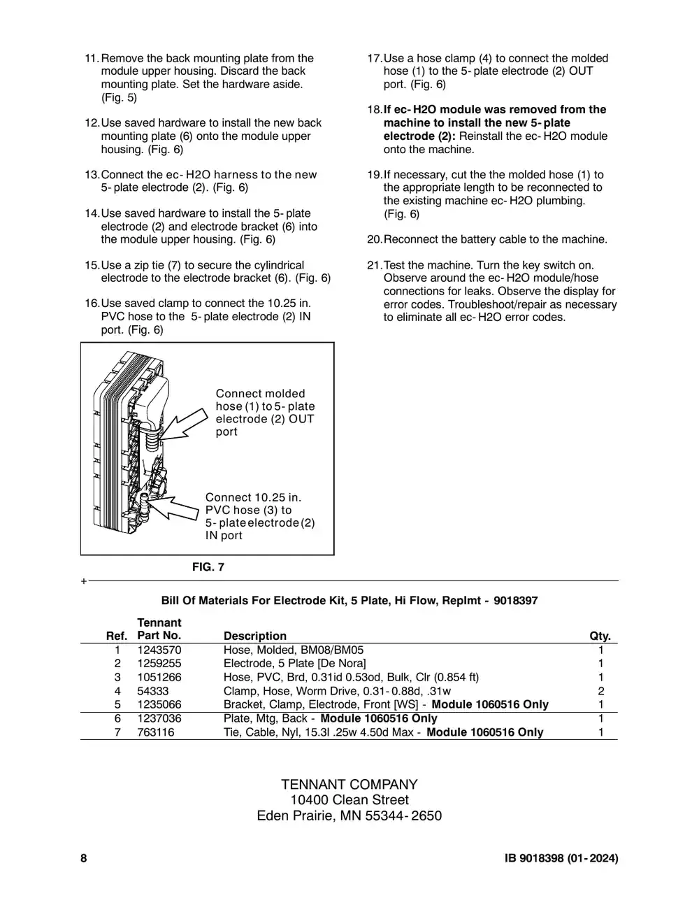
8. Disconnect the ec- H2O harness connections from the bottom of the 5- plate electrode. Discard the 5- plate electrode. (Fig. 1) 9. Connect the ec- H2O harness to the new 5- plate electrode (2). (Fig. 1) 10.Use saved hardware to install the 5- plate electrode (2) into the module upper housing. (Fig. 1/Fig. 3/Fig. 4) 11.Use saved clamp to connect the 10.25 in. PVC hose to the 5- plate electrode (2) IN port. (Fig. 2) Connect molded hose (1) to 5- plate electrode (2) OUT port Connect 10.25 in. PVC hose (3) to 5- plateelectrode(2) IN port FIG. 2 12.Use a hose clamp (4) to connect the molded hose (1) to the 5- plate electrode (2) OUT port. (Fig. 2) IB 9018398 (01- 2024) 13.Reinstall module upper housing onto the bottom housing. Do Not pinch hoses/wires between the module upper housing and the bottom housing. (Fig. 1/Fig. 3/Fig. 4) 14.If ec- H2O module was removed from the machine to install the new 5- plate electrode (2): Reinstall the ec- H2O module onto the machine. 15.If necessary, cut the the molded hose (1) to the appropriate length to be reconnected to the existing machine ec- H2O plumbing. (Fig. 1) 16.Reconnect the battery cable to the machine. 17.Test the machine. Turn the key switch on. Observe around the ec- H2O module/hose connections for leaks. Observe the display for error codes. Troubleshoot/repair as necessary to eliminate all ec- H2O error codes. 3
Tennant M20 instruction bulletin 9018398, page 4 of 8
Page 4 of 8
Text of this page
Cylindrical electrode FIG. 3 - 4 Module upper housing 2 ec- H2O harness 3 Large valve bracket 4 Bottom housing 1 1049958 IB 9018398 (01- 2024)
Tennant M20 instruction bulletin 9018398, page 5 of 8
Page 5 of 8
Text of this page
2 4 3 Cylindrical electrode FIG. 4 - IB 9018398 (01- 2024) Module upper housing ec- H2O harness 1 Large valve bracket Bottom housing 1212103 5
Tennant M20 instruction bulletin 9018398, page 6 of 8
Page 6 of 8
Text of this page
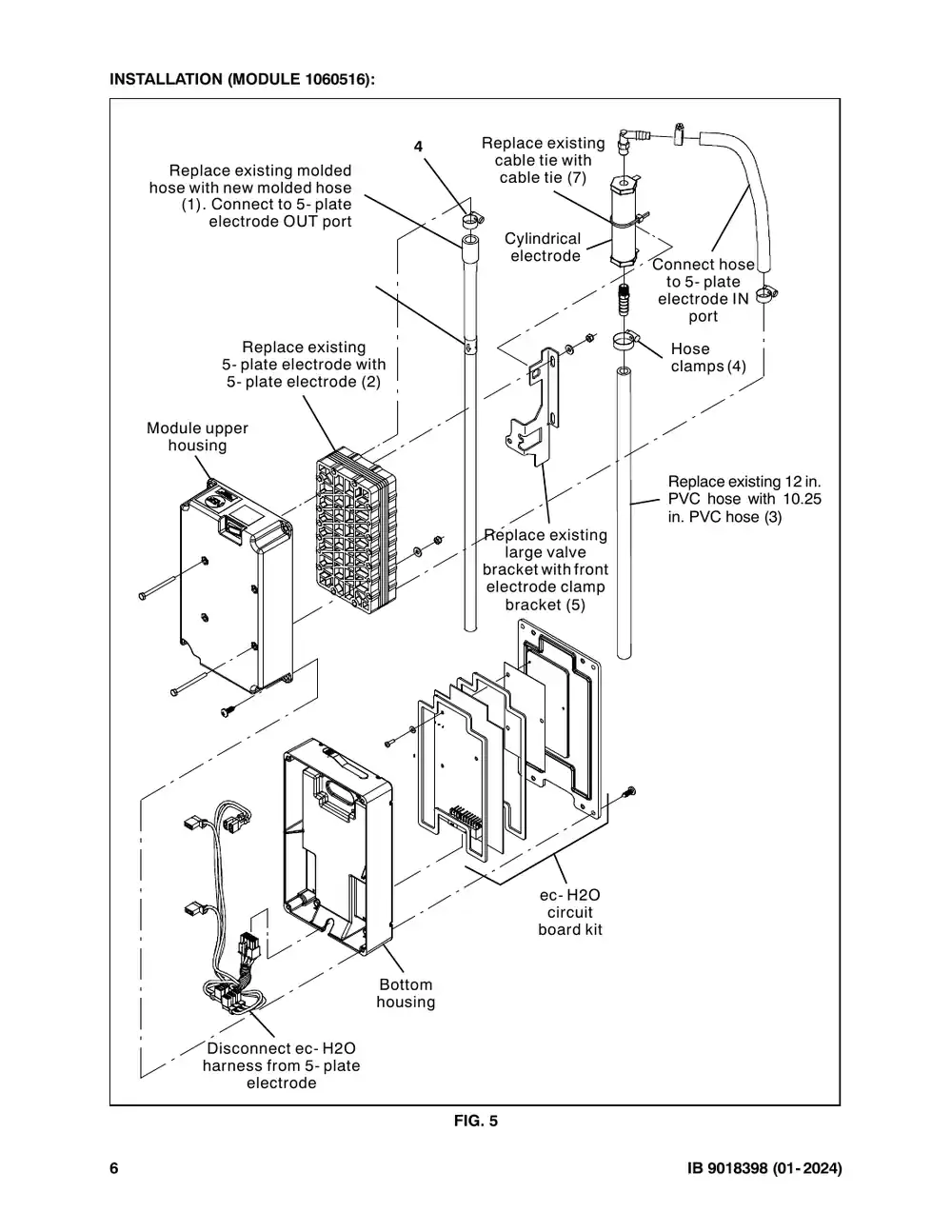
INSTALLATION (MODULE 1060516): 4 Replace existing molded hose with new molded hose (1). Connect to 5- plate electrode OUT port Replace existing 5- plate electrode with 5- plate electrode (2) Module upper housing Bottom housing Disconnect ec- H2O harness from 5- plate electrode FIG 6 Replace existing cable tie with cable tie (7) Cylindrical electrode Connect hose to 5- plate electrode IN port Hose clamps(4) Replace existing 12 in. PVC hose with 10.25 in. PVC hose (3) Replace existing large valve bracket with front electrode clamp bracket (5) ec- H2O circuit board kit G. 5 IB 9018398 (01- 2024)
Tennant M20 instruction bulletin 9018398, page 7 of 8
Page 7 of 8
Text of this page
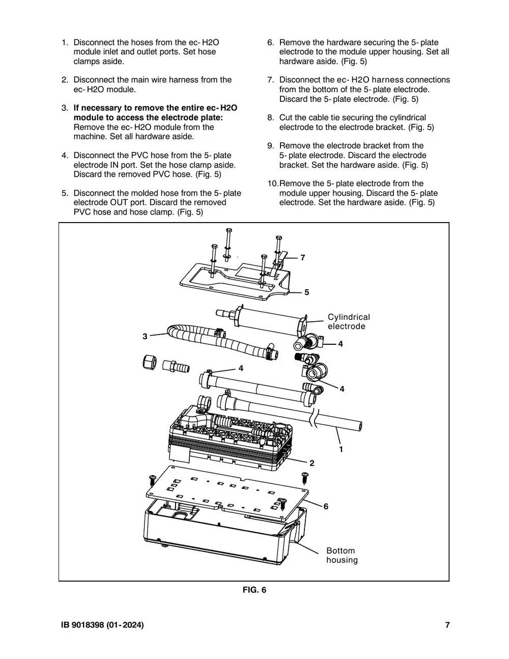
1. Disconnect the hoses from the ec- H2O module inlet and outlet ports. Set hose clamps aside. 2. Disconnect the main wire harness from the ec- H2O module. 3. If necessary to remove the entire ec- H2O module to access the electrode plate: Remove the ec- H2O module from the machine. Set all hardware aside. 4. Disconnect the PVC hose from the 5- plate electrode IN port. Set the hose clamp aside. Discard the removed PVC hose. (Fig. 5) 5. Disconnect the molded hose from the 5- plate electrode OUT port. Discard the removed PVC hose and hose clamp. (Fig. 5) 3 4 FIG IB 9018398 (01- 2024) 6. Remove the hardware securing the 5- plate electrode to the module upper housing. Set all hardware aside. (Fig. 5) 7. Disconnect the ec- H2O harness connections from the bottom of the 5- plate electrode. Discard the 5- plate electrode. (Fig. 5) 8. Cut the cable tie securing the cylindrical electrode to the electrode bracket. (Fig. 5) 9. Remove the electrode bracket from the 5- plate electrode. Discard the electrode bracket. Set the hardware aside. (Fig. 5) 10.Remove the 5- plate electrode from the module upper housing. Discard the 5- plate electrode. Set the hardware aside. (Fig. 5) 7 5 Cylindrical electrode 4 4 1 2 6 Bottom housing G. 6 7
Tennant M20 instruction bulletin 9018398, page 8 of 8
Page 8 of 8
Text of this page
11.Remove the back mounting plate from the module upper housing. Discard the back mounting plate. Set the hardware aside. (Fig. 5) 12.Use saved hardware to install the new back mounting plate (6) onto the module upper housing. (Fig. 6) 13.Connect the ec- H2O harness to the new 5- plate electrode (2). (Fig. 6) 14.Use saved hardware to install the 5- plate electrode (2) and electrode bracket (6) into the module upper housing. (Fig. 6) 15.Use a zip tie (7) to secure the cylindrical electrode to the electrode bracket (6). (Fig. 6) 16.Use saved clamp to connect the 10.25 in. PVC hose to the 5- plate electrode (2) IN port. (Fig. 6) Connect molded hose (1) to 5- plate electrode (2) OUT port Connect 10.25 in. PVC hose (3) to 5- plateelectrode(2) IN port FIG. 7 + Bill Of Materials For Electrode Kit, Tennant Ref. Part No. Description 1 TN4034288 ) Hose, Molded, BM08/BM 2 TN4032414 Electrode, 5 Plate [De No 3 TN4040768 Hose, PVC, Brd, 0.31id 0 4 TN4015366 Clamp, Hose, Worm Driv 5 TN4033062 Bracket, Clamp, Electrod 6 TN4033367 ) Plate, Mtg, Back - Modu 7 TN4011910 Tie, Cable, Nyl, 15.3l .25w TENNANT 10400 Cle Eden Prairie, M 8 17.Use a hose clamp (4) to connect the molded hose (1) to the 5- plate electrode (2) OUT port. (Fig. 6) 18.If ec- H2O module was removed from the machine to install the new 5- plate electrode (2): Reinstall the ec- H2O module onto the machine. 19.If necessary, cut the the molded hose (1) to the appropriate length to be reconnected to the existing machine ec- H2O plumbing. (Fig. 6) 20.Reconnect the battery cable to the machine. 21.Test the machine. Turn the key switch on. Observe around the ec- H2O module/hose connections for leaks. Observe the display for error codes. Troubleshoot/repair as necessary to eliminate all ec- H2O error codes. 5 Plate, Hi Flow, Replmt - TN4020962 Qty. M05 1 ora] 1 0.53od, Bulk, Clr (0.854 ft) 1 ve, 0.31- 0.88d, .31w 2 de, Front [WS] - Module 1060516 Only 1 ule 1060516 Only 1 w 4.50d Max - Module 1060516 Only 1 COMPANY ean Street MN 55344- 2650 IB 9018398 (01- 2024)

Nozzle Kit, Spray, CI [M20/T20]

Tennant instruction bulletin 9021861 rev. 00Published 01-2024Kit 9021851

What it’s for: Install a spray nozzle kit onto: M20 sweeper scrubbers (NA serial numbers 014001- ) (CE serial numbers UO1500- )/ T20 scrubbers (NA serial numbers 013001- ) (CE serial numbers UO1400- ).

  • Machines: M20, T20
  • M20 SN 014001 and later
  • Power: gasoline, LPG and diesel
  • Applies to: spray nozzle

Time: 3 hours · Special tools: NONE

Safety warnings (from the bulletin, word for word)

  • WARNING: Lift arm pinch point. Stay clear of hopper lift arms.
  • WARNING: Raised hopper may fall. Engage hopper support pin.
  • FOR SAFETY: Before leaving or servicing machine, stop on level surface, turn off machine, set parking brake, and remove key.
  • WARNING: Always disconnect battery cables from machine before working on electrical components.
  • FOR SAFETY: When servicing machine, avoid contact with battery acid. 1

Tennant says an authorized service provider should install this kit. SES is one: Have SES install this kit.

Parts

Parts for Tennant instruction bulletin 9021861
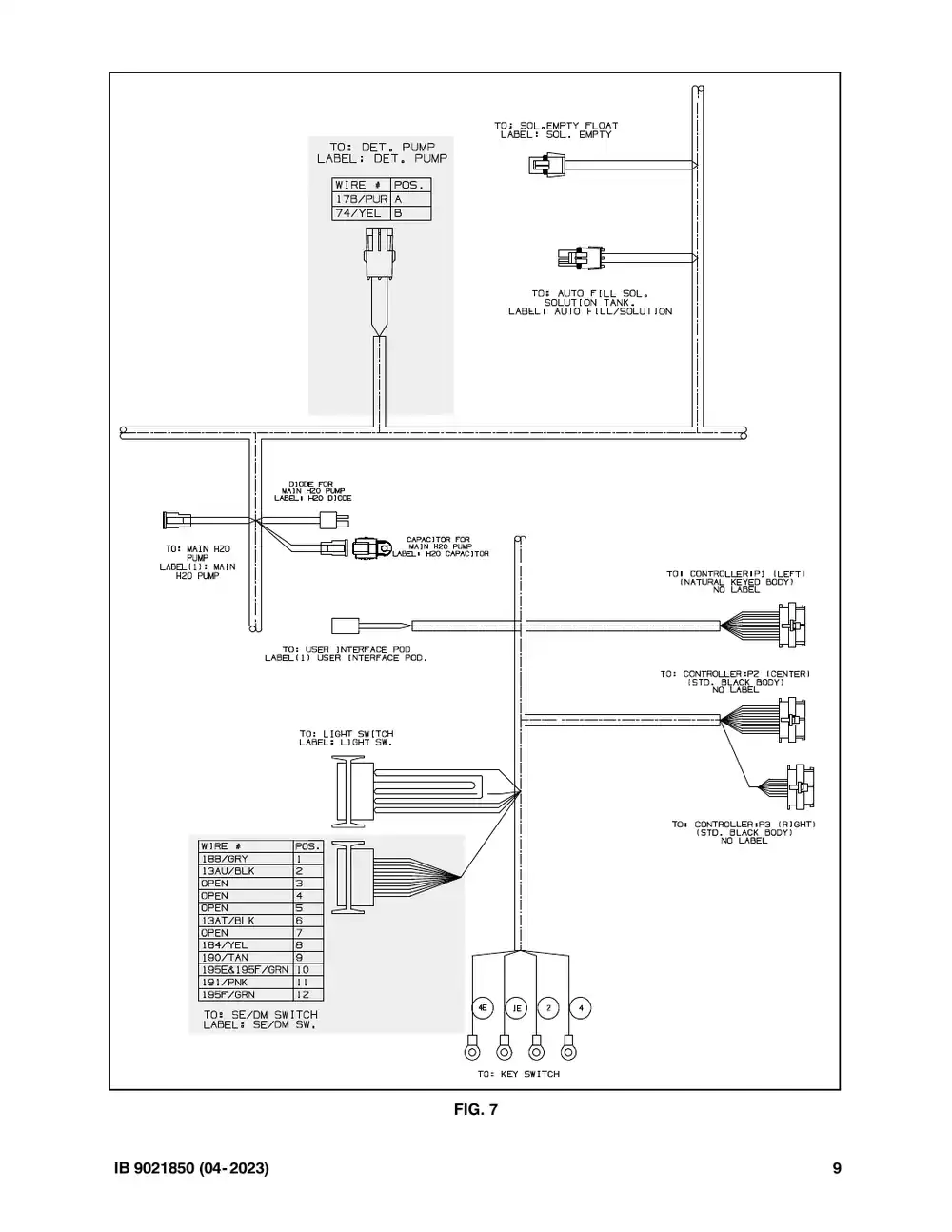
ItemPart numberQtyDescriptionPrice
TN4018390Old # 90218511Nozzle Kit, Spray, CI [M20/T20]KitCall for availability 800-440-6723
1TN4042944Old # 10768702Valve, Water, Solenoid [12vdc, Bm08/Bm08]$122.10/EA
2TN4015366Old # 5433310Clamp, Hose, Wormdrive, 0.31- 0.88d, .31w$5.10/EA
3TN4017637Old # 647432Fitting, Plstc, Str, Bm08/Pm06$6.20/EA
4TN4011920Old # 7631494Screw, Pan, 06- X 0.38, F/ PlstcCall for availability 800-440-6723
5TN4029123Old # 561861Relay, 12vdc, 40a, Spdt N/O$11.30/EA
6TN5000159Old # 3767162Hose, PVC, Brd, 0.50ID 0.73OD, Bulk, Clr (1.8 in. (46 mm))Call for availability 800-440-6723
7TN4042976Old # 10769741Harness, Spray, Nozzle$59.01/EA
8TN4035902Old # 10192501Hose, Water, Coil$192.50/EA
9TN4028980Old # 7697851Nozzle, Spray, Gun$90.00/EA
10TN4030660Old # 10279761Fitting, Brs, Str, Pf06/Pm12$11.80/EA
11TN4030624Old # 10272371Bracket, Mtg, Spray Handle$15.30/EA
12TN4042902Old # 016852Washer, Flat, 0.38b 0.88d .08, SS$2.60/EA
13TN4041943Old # 090102Screw, Hex, M8 X 1.25 X 25, SS$3.30/EA
14TN4016537Old # 3985001Switch, Rocker, Dpdt On/None/On$45.20/EA
15TN4031379Old # 10297901Bracket, Mtg, Spray Wand [FaST, Conv]$26.25/EA
16TN4041992Old # 097402Screw, Hex, M8 X 1.25 X 20, SS$3.30/EA
17TN4035242Old # 10172182Washer, Flat, 0.32b 1.00d .12, SS$3.40/EA
18TN4030661Old # 10279781Fitting, Brs, Str, Pf06/Pf06 Bh$23.25/EA
19TN4017647Old # 647782Fitting, Plstc, E90, Bm08/Pm06$8.70/EA
20TN4031028Old # 10290551Wand, Clean- Out$176.10/EA
21TN4031029Old # 10290572Clip, Grip, Finger, .875- 1.25$5.15/EA
22TN4039088Old # 203942Screw, Hex, #10- 16 X 0.62, Fmg [Ab]$3.30/EA
23TN4042888Old # 016834Washer, Flat, #10, SS$2.60/EA
24TN4029238Old # 3753211Fitting, Brs, Str, Pm08/Garden Hose$10.40/EA
25TN4042839Old # 013161Washer, Flat, 0.66b 1.00d .12, Rbr$3.50/EA
26TN4031038Old # 10291531Fitting, Brs, Spcl [Garden Hose]$7.00/EA
27TN4031039Old # 10291551Coupling, Nozzle, Spray$15.40/EA
28TN4031040Old # 10291561Nozzle$69.50/EA
29TN4031357Old # 10293991Valve, Shutoff$41.60/EA
30TN4020528Old # 6301463Fitting, Plug, Pm06, Hdpe$4.00/EA
31TN4032111Old # 12548331Manifold, Soln$121.00/EA
32TN4032116Old # 12548561Plate, Manifold, Mtg$25.55/EA
33TN4034136Old # 3249010Washer, Flat, 0.25, Std$2.50/EA
34TN4032379Old # 12578006Screw, Hex, M6 X 1.00 X 60, SS, Fl$14.14/EA
35TN4041928Old # 087124Nut, Hex, Lock, M6 X 1.00, Nl, SS$2.50/EA
36TN4043042Old # 10771241Bracket, Manifold, Stratus$10.20/EA
37TN5000159Old # 3767161Hose, PVC, Brd, 0.50ID 0.73OD, Bulk, Clr (99.6 in. (2530 mm))Call for availability 800-440-6723
38TN5000159Old # 3767161Hose, PVC, Brd, 0.50ID 0.73OD, Bulk, Clr (93.6 in. (2377 mm))Call for availability 800-440-6723
39TN5000159Old # 3767161Hose, PVC, Brd, 0.50ID 0.73OD, Bulk, Clr (51.6 in. (1311 mm))Call for availability 800-440-6723
40TN4041267Old # 069382Screw, Pan, Phl, M5 X 0.80 X 40, 4.8$1.82/EA
41TN4041004Old # 065492Nut, Hex, M5 X 0.80 X 16, 8.8$2.50/EA
42TN4017396Old # 438441Clamp, Hose, Worm Drive, 0.25- 0.62D, .31W$4.20/EA
43TN5000159Old # 3767161Hose, PVC, Brd, 0.50ID 0.73OD, Bulk, Clr (72 in. (1829 mm))Call for availability 800-440-6723

Bulletin PDF: Sign in to view or downloadSign in to download

Installation instructions (11 pages)
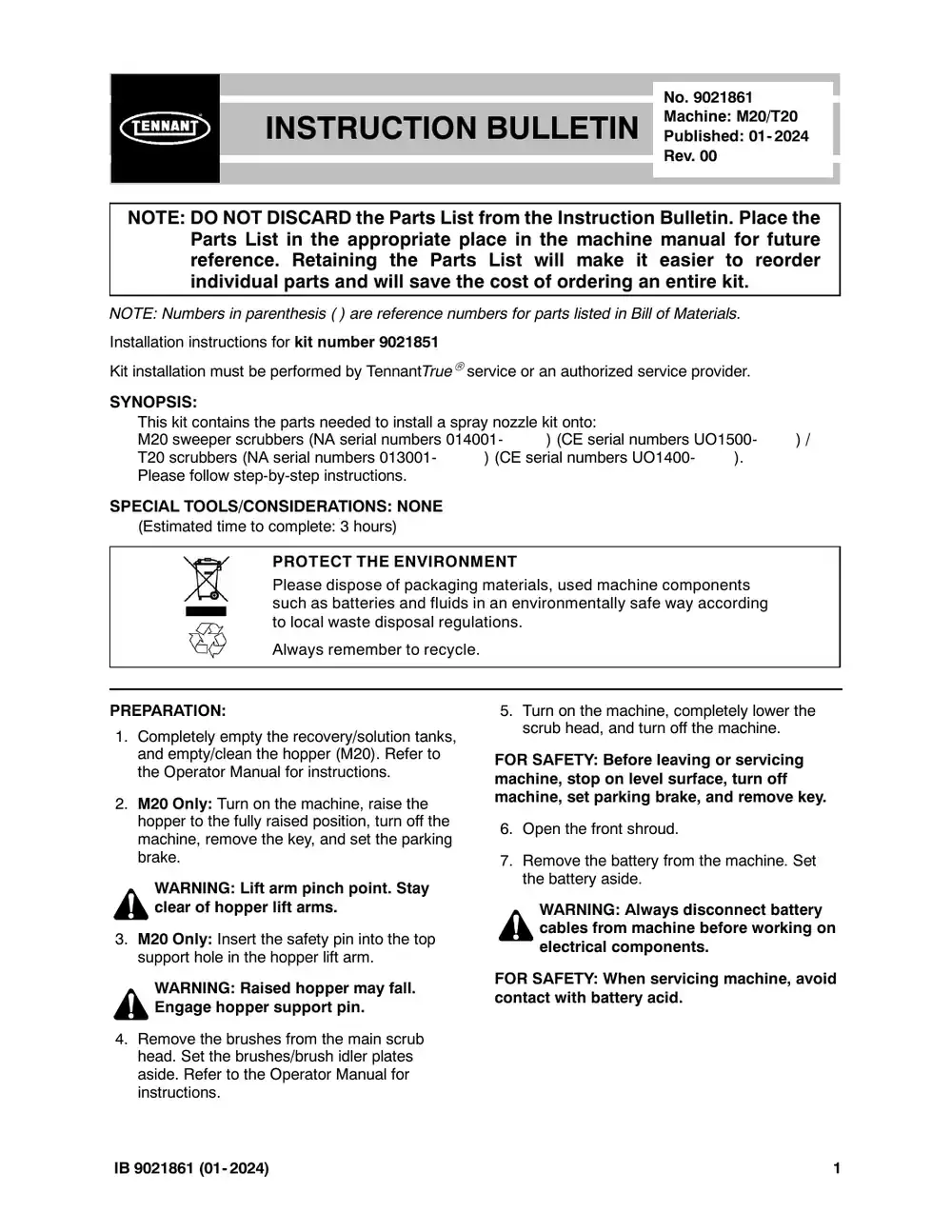
Tennant M20 instruction bulletin 9021861, page 1 of 11
Page 1 of 11 SES ref PF-I2NO-RR4Q‌‌​⁠‍‍‌​‌​‍‌⁠‌⁠​⁠‌‌⁠​‍⁠⁠​​​​​​​‌​‍‌​‌‍‌‌​‍⁠⁠‌​‍⁠‍‌​‌​​‌‍‌​‍​
Text of this page
INSTRUCTION NOTE: DO NOT DISCARD the Parts List Parts List in the appropriate pla reference. Retaining the Parts individual parts and will save the NOTE: Numbers in parenthesis ( ) are reference num Installation instructions for kit number TN4018390 Kit installation must be performed by TennantTruese SYNOPSIS: This kit contains the parts needed to install a spra M20 sweeper scrubbers (NA serial numbers 0140 T20 scrubbers (NA serial numbers 013001- Please follow step-by-step instructions. SPECIAL TOOLS/CONSIDERATIONS: NONE (Estimated time to complete: 3 hours) PROTECT THE ENVIRONM Please dispose of packaging such as batteries and fluids i to local waste disposal regula Always remember to recycle. PREPARATION: 1. Completely empty the recovery/solution tanks, and empty/clean the hopper (M20). Refer to the Operator Manual for instructions. 2. M20 Only: Turn on the machine, raise the hopper to the fully raised position, turn off the machine, remove the key, and set the parking brake. WARNING: Lift arm pinch point. Stay clear of hopper lift arms. 3. M20 Only: Insert the safety pin into the top support hole in the hopper lift arm. WARNING: Raised hopper may fall. Engage hopper support pin. 4. Remove the brushes from the main scrub head. Set the brushes/brush idler plates aside. Refer to the Operator Manual for instructions. IB 9021861 (01- 2024) No. 9021861 Machine: M20/T20 N BULLETIN Published: 01- 2024 Rev. 00 from the Instruction Bulletin. Place the ace in the machine manual for future s List will make it easier to reorder e cost of ordering an entire kit. mbers for parts listed in Bill of Materials. ervice or an authorized service provider. ay nozzle kit onto: 001- ) (CE serial numbers UO1500- ) / ) (CE serial numbers UO1400- ). MENT g materials, used machine components in an environmentally safe way according ations. . 5. Turn on the machine, completely lower the scrub head, and turn off the machine. FOR SAFETY: Before leaving or servicing machine, stop on level surface, turn off machine, set parking brake, and remove key. 6. Open the front shroud. 7. Remove the battery from the machine. Set the battery aside. WARNING: Always disconnect battery cables from machine before working on electrical components. FOR SAFETY: When servicing machine, avoid contact with battery acid. 1
Tennant M20 instruction bulletin 9021861, page 2 of 11
Page 2 of 11
Text of this page
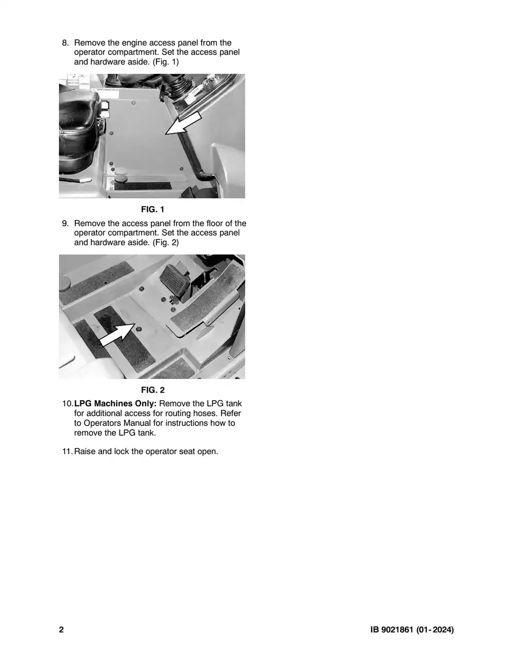
8. Remove the engine access panel from the operator compartment. Set the access panel and hardware aside. (Fig. 1) FIG. 1 9. Remove the access panel from the floor of the operator compartment. Set the access panel and hardware aside. (Fig. 2) FIG. 2 10.LPG Machines Only: Remove the LPG tank for additional access for routing hoses. Refer to Operators Manual for instructions how to remove the LPG tank. 11.Raise and lock the operator seat open. 2 IB 9021861 (01- 2024)
Tennant M20 instruction bulletin 9021861, page 3 of 11
Page 3 of 11
Text of this page
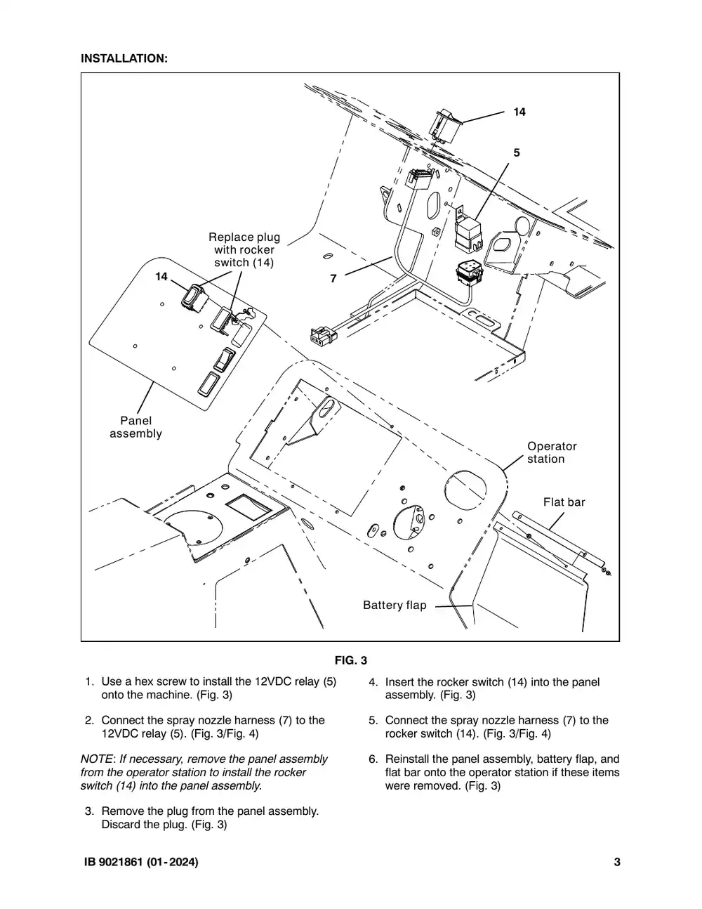
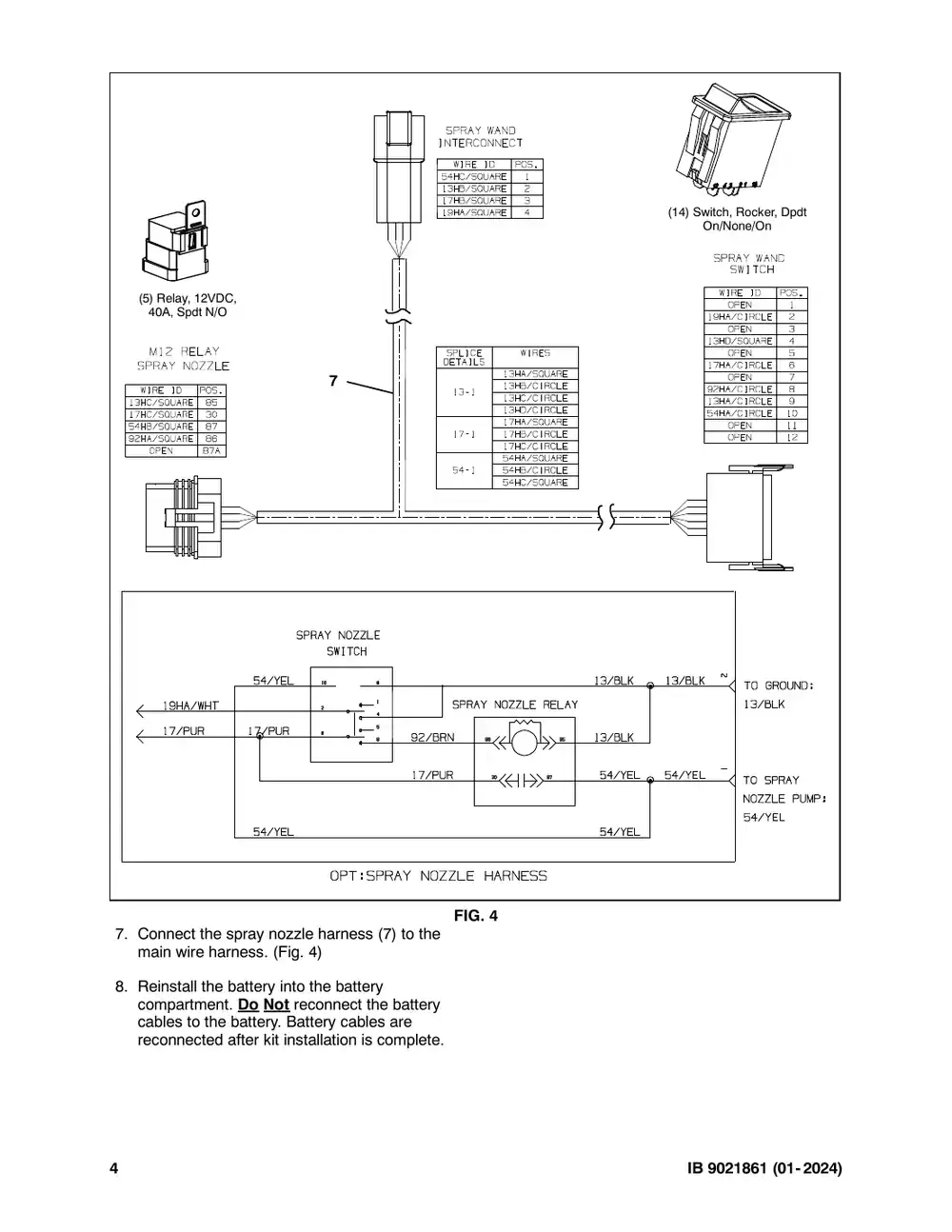
INSTALLATION: Replace plug with rocker switch (14) 14 7 Panel assembly FIG 1. Use a hex screw to install the 12VDC relay (5) onto the machine. (Fig. 3) 2. Connect the spray nozzle harness (7) to the 12VDC relay (5). (Fig. 3/Fig. 4) NOTE: If necessary, remove the panel assembly from the operator station to install the rocker switch (14) into the panel assembly. 3. Remove the plug from the panel assembly. Discard the plug. (Fig. 3) IB 9021861 (01- 2024) 14 5 Operator station Flat bar Battery flap G. 3 4. Insert the rocker switch (14) into the panel assembly. (Fig. 3) 5. Connect the spray nozzle harness (7) to the rocker switch (14). (Fig. 3/Fig. 4) 6. Reinstall the panel assembly, battery flap, and flat bar onto the operator station if these items were removed. (Fig. 3) 3
Tennant M20 instruction bulletin 9021861, page 4 of 11
Page 4 of 11
Text of this page
(5) Relay, 12VDC, 40A, Spdt N/O 7 FIG 7. Connect the spray nozzle harness (7) to the main wire harness. (Fig. 4) 8. Reinstall the battery into the battery compartment. Do Not reconnect the battery cables to the battery. Battery cables are reconnected after kit installation is complete. 4 (14) Switch, Rocker, Dpdt On/None/On G. 4 IB 9021861 (01- 2024)
Tennant M20 instruction bulletin 9021861, page 5 of 11
Page 5 of 11
Text of this page
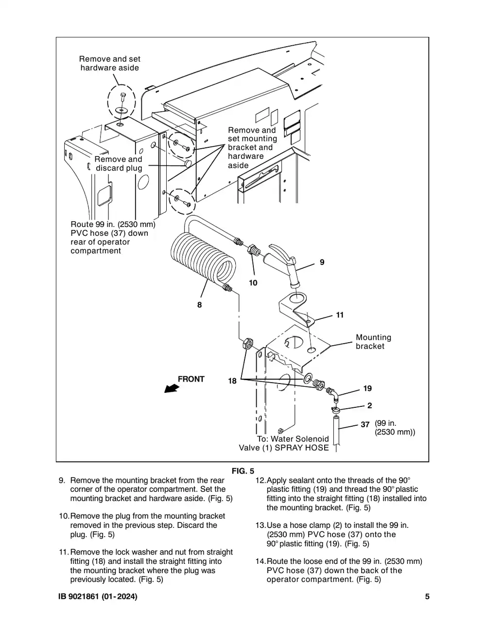
Remove and set hardware aside Rem set m brac hard Remove and asid discard plug Route 99 in. (2530 mm) PVC hose (37) down rear of operator compartment 8 FRONT 18 V FIG 9. Remove the mounting bracket from the rear corner of the operator compartment. Set the mounting bracket and hardware aside. (Fig. 5) 10.Remove the plug from the mounting bracket removed in the previous step. Discard the plug. (Fig. 5) 11.Remove the lock washer and nut from straight fitting (18) and install the straight fitting into the mounting bracket where the plug was previously located. (Fig. 5) IB 9021861 (01- 2024) move and mounting cket and dware de 9 10 11 Mounting bracket 19 2 37 (99 in. (2530 mm)) To: Water Solenoid Valve (1) SPRAY HOSE G. 5 12.Apply sealant onto the threads of the 90° plastic fitting (19) and thread the 90° plastic fitting into the straight fitting (18) installed into the mounting bracket. (Fig. 5) 13.Use a hose clamp (2) to install the 99 in. (2530 mm) PVC hose (37) onto the 90° plastic fitting (19). (Fig. 5) 14.Route the loose end of the 99 in. (2530 mm) PVC hose (37) down the back of the operator compartment. (Fig. 5) 5
Tennant M20 instruction bulletin 9021861, page 6 of 11
Page 6 of 11
Text of this page
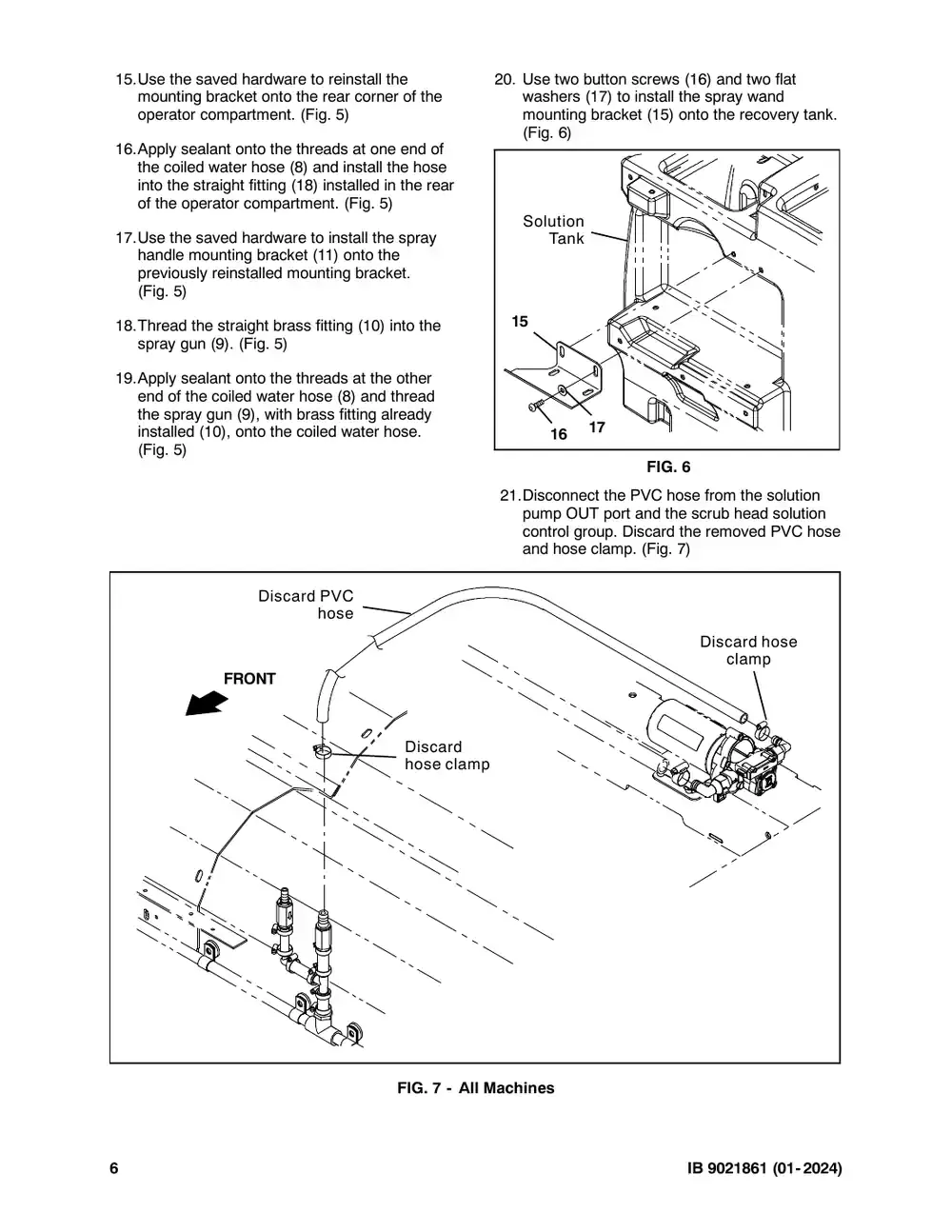
15.Use the saved hardware to reinstall the mounting bracket onto the rear corner of the operator compartment. (Fig. 5) 16.Apply sealant onto the threads at one end of the coiled water hose (8) and install the hose into the straight fitting (18) installed in the rear of the operator compartment. (Fig. 5) 17.Use the saved hardware to install the spray handle mounting bracket (11) onto the previously reinstalled mounting bracket. (Fig. 5) 18.Thread the straight brass fitting (10) into the spray gun (9). (Fig. 5) 19.Apply sealant onto the threads at the other end of the coiled water hose (8) and thread the spray gun (9), with brass fitting already installed (10), onto the coiled water hose. (Fig. 5) Discard PVC hose FRONT Discard hose clam FIG. 7 - All 6 20. Use two button screws (16) and two flat washers (17) to install the spray wand mounting bracket (15) onto the recovery tank. (Fig. 6) Solution Tank 15 17 16 FIG. 6 21.Disconnect the PVC hose from the solution pump OUT port and the scrub head solution control group. Discard the removed PVC hose and hose clamp. (Fig. 7) Discard hose clamp mp l Machines IB 9021861 (01- 2024)
Tennant M20 instruction bulletin 9021861, page 7 of 11
Page 7 of 11
Text of this page
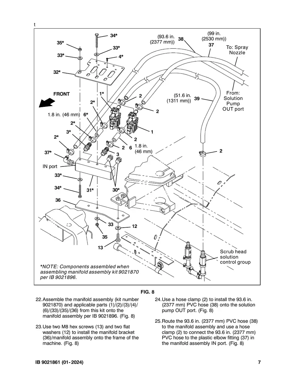
t 34* 35* 33* 33* 4* 32* FRONT 1* 2 2* 1.8 in. (46 mm) 6* 2* 3* 2* 2 1.8 in. 2 6 37* (46 mm 3 IN port 33* 34* 31* 30* 36 33 12 35 13 *NOTE: Components assembled when assembling manifold assembly kit 9021870 per IB 9021896. FIG 22.Assemble the manifold assembly (kit number 9021870) and applicable parts (1)/(2)/(3)/(4)/ (6)/(33)/(35)/(36) from this kit onto the manifold assembly per IB 9021896. (Fig. 8) 23.Use two M8 hex screws (13) and two flat washers (12) to install the manifold bracket (36)/manifold assembly onto the frame of the machine. (Fig. 8) IB 9021861 (01- 2024) (99 in. (93.6 in. 38 (2530 mm)) (2377 mm)) 37 To: Spray Nozzle From: (51.6 in. 39 Solution (1311 mm)) Pump OUT port 2 1 . m) 2 Scrub head solution control group G. 8 24.Use a hose clamp (2) to install the 93.6 in. (2377 mm) PVC hose (38) onto the solution pump OUT port. (Fig. 8) 25.Route the 93.6 in. (2377 mm) PVC hose (38) to the manifold assembly and use a hose clamp (2) to connect the 93.6 in. (2377 mm) PVC hose to the plastic elbow fitting (37) in the manifold assembly IN port. (Fig. 8) 7
Tennant M20 instruction bulletin 9021861, page 8 of 11
Page 8 of 11
Text of this page
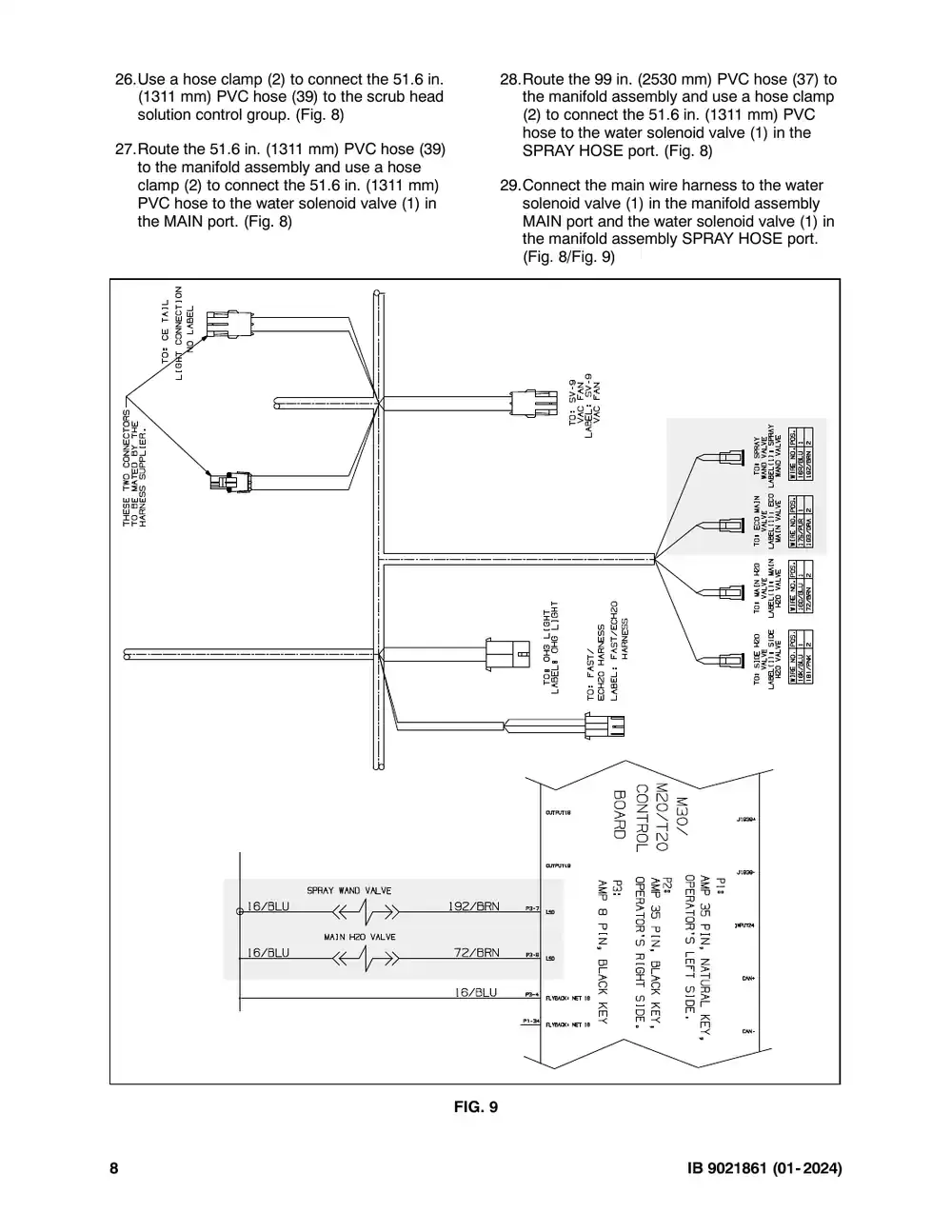
26.Use a hose clamp (2) to connect the 51.6 in. (1311 mm) PVC hose (39) to the scrub head solution control group. (Fig. 8) 27.Route the 51.6 in. (1311 mm) PVC hose (39) to the manifold assembly and use a hose clamp (2) to connect the 51.6 in. (1311 mm) PVC hose to the water solenoid valve (1) in the MAIN port. (Fig. 8) FIG 8 28.Route the 99 in. (2530 mm) PVC hose (37) to the manifold assembly and use a hose clamp (2) to connect the 51.6 in. (1311 mm) PVC hose to the water solenoid valve (1) in the SPRAY HOSE port. (Fig. 8) 29.Connect the main wire harness to the water solenoid valve (1) in the manifold assembly MAIN port and the water solenoid valve (1) in the manifold assembly SPRAY HOSE port. (Fig. 8/Fig. 9) G. 9 IB 9021861 (01- 2024)
Tennant M20 instruction bulletin 9021861, page 9 of 11
Page 9 of 11
Text of this page
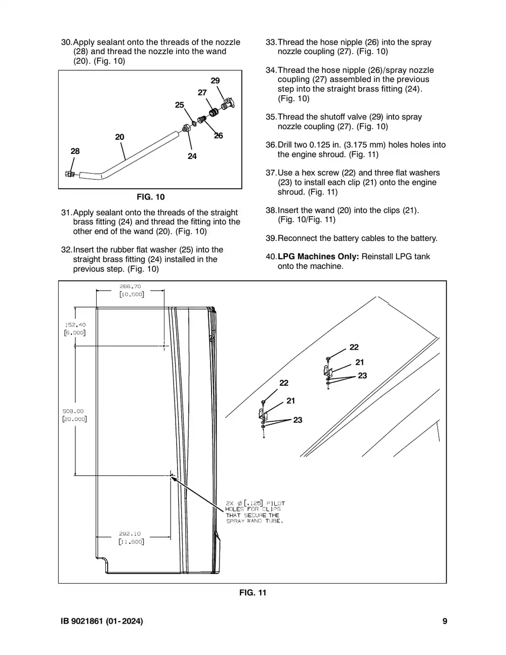
30.Apply sealant onto the threads of the nozzle (28) and thread the nozzle into the wand (20). (Fig. 10) 29 27 25 20 26 28 24 FIG. 10 31.Apply sealant onto the threads of the straight brass fitting (24) and thread the fitting into the other end of the wand (20). (Fig. 10) 32.Insert the rubber flat washer (25) into the straight brass fitting (24) installed in the previous step. (Fig. 10) FIG IB 9021861 (01- 2024) 33.Thread the hose nipple (26) into the spray nozzle coupling (27). (Fig. 10) 34.Thread the hose nipple (26)/spray nozzle coupling (27) assembled in the previous step into the straight brass fitting (24). (Fig. 10) 35.Thread the shutoff valve (29) into spray nozzle coupling (27). (Fig. 10) 36.Drill two 0.125 in. (3.175 mm) holes holes into the engine shroud. (Fig. 11) 37.Use a hex screw (22) and three flat washers (23) to install each clip (21) onto the engine shroud. (Fig. 11) 38.Insert the wand (20) into the clips (21). (Fig. 10/Fig. 11) 39.Reconnect the battery cables to the battery. 40.LPG Machines Only: Reinstall LPG tank onto the machine. 22 21 23 22 21 23 G. 11 9
Tennant M20 instruction bulletin 9021861, page 10 of 11
Page 10 of 11
Text of this page
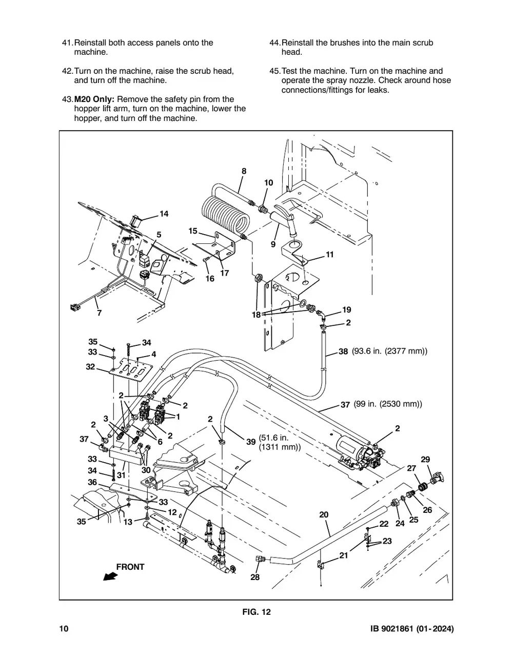
41.Reinstall both access panels onto the machine. 42.Turn on the machine, raise the scrub head, and turn off the machine. 43.M20 Only: Remove the safety pin from the hopper lift arm, turn on the machine, lower the hopper, and turn off the machine. 8 14 15 5 17 16 7 18 35 34 33 4 32 2 2 3 1 2 2 2 37 6 39 33 34 30 31 36 33 12 35 13 FRONT 28 FIG 10 44.Reinstall the brushes into the main scrub head. 45.Test the machine. Turn on the machine and operate the spray nozzle. Check around hose connections/fittings for leaks. 10 9 11 19 8 2 38 (93.6 in. (2377 mm)) 37 (99 in. (2530 mm)) 2 (51.6 in. (1311 mm)) 29 27 26 20 25 22 24 23 21 8 G. 12 IB 9021861 (01- 2024)
Tennant M20 instruction bulletin 9021861, page 11 of 11
Page 11 of 11
Text of this page
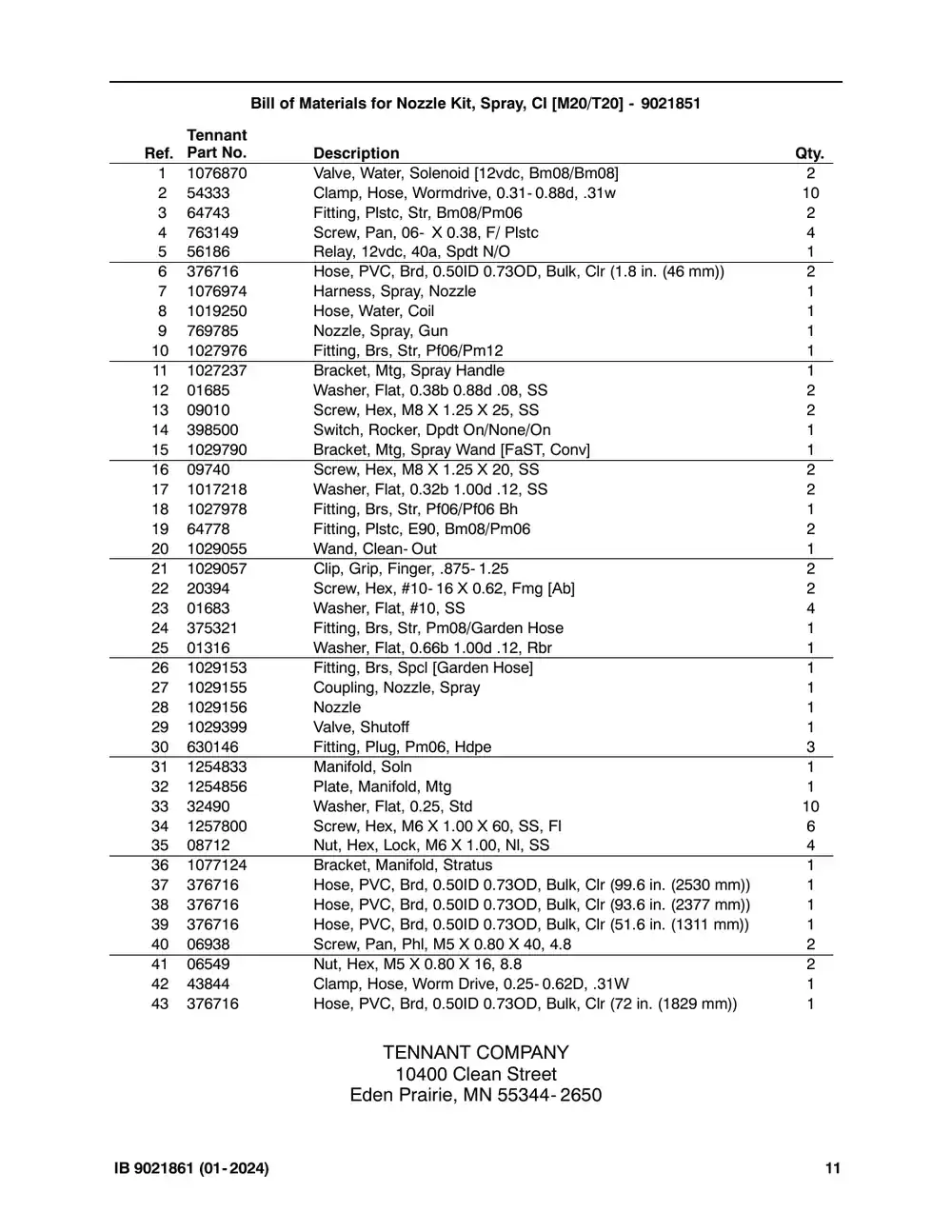
Bill of Materials for Nozzle Kit, Spray, CI [M20/T20] - TN4018390 Tennant Ref. Part No. Description Qty. 1 TN4042944 Valve, Water, Solenoid [12vdc, Bm08/Bm08] 2 2 TN4015366 Clamp, Hose, Wormdrive, 0.31- 0.88d, .31w 10 3 TN4017637 Fitting, Plstc, Str, Bm08/Pm06 2 4 TN4011920 Screw, Pan, 06- X 0.38, F/ Plstc 4 5 TN4029123 Relay, 12vdc, 40a, Spdt N/O 1 6 TN5000159 Hose, PVC, Brd, 0.50ID 0.73OD, Bulk, Clr (1.8 in. (46 mm)) 2 7 TN4042976 Harness, Spray, Nozzle 1 8 TN4035902 Hose, Water, Coil 1 9 TN4028980 Nozzle, Spray, Gun 1 10 TN4030660 Fitting, Brs, Str, Pf06/Pm12 1 11 TN4030624 Bracket, Mtg, Spray Handle 1 12 TN4042902 Washer, Flat, 0.38b 0.88d .08, SS 2 13 TN4041943 Screw, Hex, M8 X 1.25 X 25, SS 2 14 TN4016537 Switch, Rocker, Dpdt On/None/On 1 15 TN4031379 Bracket, Mtg, Spray Wand [FaST, Conv] 1 16 TN4041992 Screw, Hex, M8 X 1.25 X 20, SS 2 17 TN4035242 Washer, Flat, 0.32b 1.00d .12, SS 2 18 TN4030661 Fitting, Brs, Str, Pf06/Pf06 Bh 1 19 TN4017647 Fitting, Plstc, E90, Bm08/Pm06 2 20 TN4031028 Wand, Clean- Out 1 21 TN4031029 Clip, Grip, Finger, .875- 1.25 2 22 TN4039088 Screw, Hex, #10- 16 X 0.62, Fmg [Ab] 2 23 TN4042888 Washer, Flat, #10, SS 4 24 TN4029238 Fitting, Brs, Str, Pm08/Garden Hose 1 25 TN4042839 Washer, Flat, 0.66b 1.00d .12, Rbr 1 26 TN4031038 Fitting, Brs, Spcl [Garden Hose] 1 27 TN4031039 Coupling, Nozzle, Spray 1 28 TN4031040 Nozzle 1 29 TN4031357 Valve, Shutoff 1 30 TN4020528 Fitting, Plug, Pm06, Hdpe 3 31 TN4032111 Manifold, Soln 1 32 TN4032116 Plate, Manifold, Mtg 1 33 TN4034136 Washer, Flat, 0.25, Std 10 34 TN4032379 Screw, Hex, M6 X 1.00 X 60, SS, Fl 6 35 TN4041928 Nut, Hex, Lock, M6 X 1.00, Nl, SS 4 36 TN4043042 Bracket, Manifold, Stratus 1 37 TN5000159 Hose, PVC, Brd, 0.50ID 0.73OD, Bulk, Clr (99.6 in. (2530 mm)) 1 38 TN5000159 Hose, PVC, Brd, 0.50ID 0.73OD, Bulk, Clr (93.6 in. (2377 mm)) 1 39 TN5000159 Hose, PVC, Brd, 0.50ID 0.73OD, Bulk, Clr (51.6 in. (1311 mm)) 1 40 TN4041267 Screw, Pan, Phl, M5 X 0.80 X 40, 4.8 2 41 TN4041004 Nut, Hex, M5 X 0.80 X 16, 8.8 2 42 TN4017396 Clamp, Hose, Worm Drive, 0.25- 0.62D, .31W 1 43 TN5000159 Hose, PVC, Brd, 0.50ID 0.73OD, Bulk, Clr (72 in. (1829 mm)) 1 TENNANT COMPANY 10400 Clean Street Eden Prairie, MN 55344- 2650 IB 9021861 (01- 2024) 11

Parts Phantom, Manifold, Aftmkt

Tennant instruction bulletin 9021896 rev. 00Published 01-2024Kit 9021870

What it’s for: Assemble a manifold assembly for: M20 sweeper scrubbers (NA serial numbers 014001- ) (CE serial numbers UO1500- ) M30 sweeper scrubbers (NA/CE serial Numbers 010001- ) T20 scrubbers (NA serial numbers 013001- ) (CE serial numbers UO1400- ).

  • Machines: M20, M30, T20
  • M20 SN 014001 and later
  • Power: gasoline, LPG and diesel

Time: 30 minutes · Special tools: NONE

Safety warnings (from the bulletin, word for word)

  • FOR SAFETY: Before leaving or servicing machine, stop on level surface, turn off machine, set parking brake, and remove key. NOTE: Refer to applicable kit/IB for locations of additional fittings installed onto the solution manifold (2).

Tennant says an authorized service provider should install this kit. SES is one: Have SES install this kit.

Parts

Parts for Tennant instruction bulletin 9021896
ItemPart numberQtyDescriptionPrice
TN4187417Old # 90218701Parts Phantom, Manifold, AftmktKitCall for availability 800-440-6723
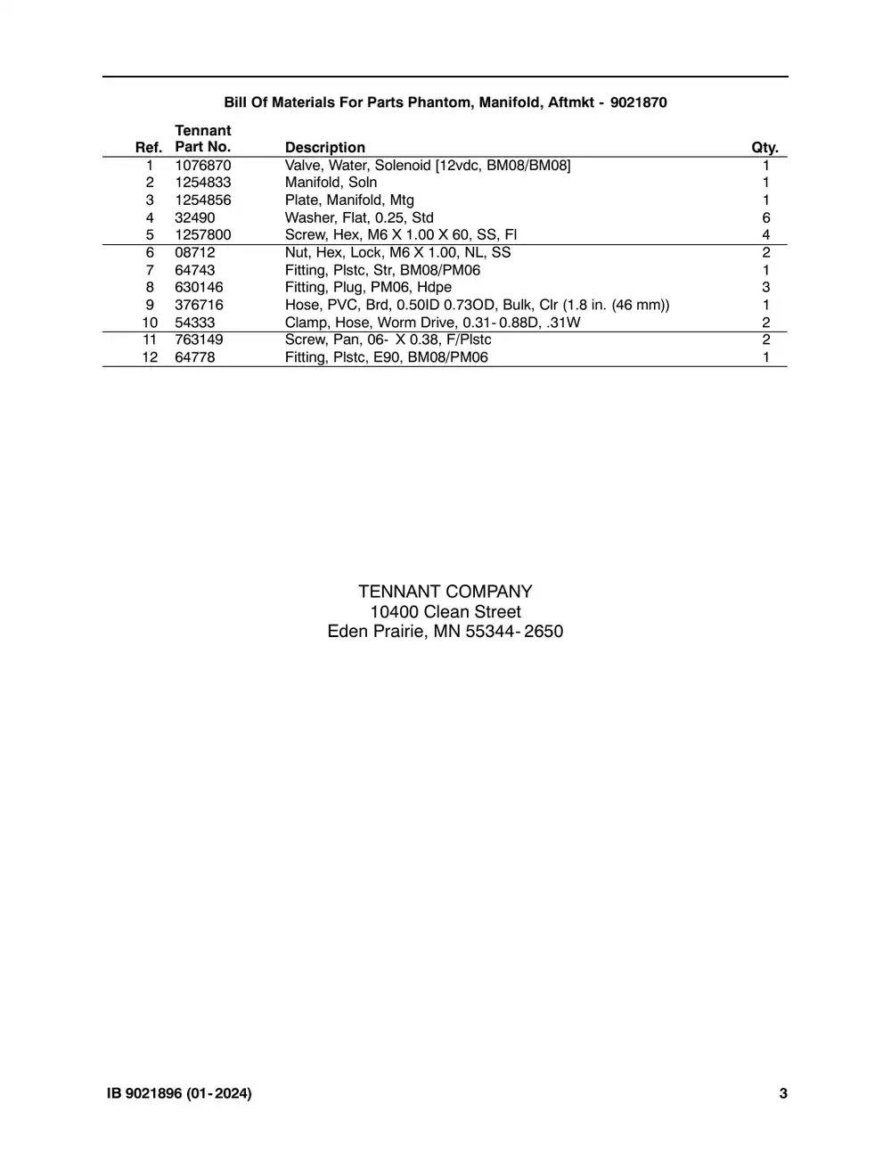
1TN4042944Old # 10768701Valve, Water, Solenoid [12vdc, BM08/BM08]$122.10/EA
2TN4032111Old # 12548331Manifold, Soln$121.00/EA
3TN4032116Old # 12548561Plate, Manifold, Mtg$25.55/EA
4TN4034136Old # 324906Washer, Flat, 0.25, Std$2.50/EA
5TN4032379Old # 12578004Screw, Hex, M6 X 1.00 X 60, SS, Fl$14.14/EA
6TN4041928Old # 087122Nut, Hex, Lock, M6 X 1.00, NL, SS$2.50/EA
7TN4017637Old # 647431Fitting, Plstc, Str, BM08/PM06$6.20/EA
8TN4020528Old # 6301463Fitting, Plug, PM06, Hdpe$4.00/EA
9TN5000159Old # 3767161Hose, PVC, Brd, 0.50ID 0.73OD, Bulk, Clr (1.8 in. (46 mm))Call for availability 800-440-6723
10TN4015366Old # 543332Clamp, Hose, Worm Drive, 0.31- 0.88D, .31W$5.10/EA
11TN4011920Old # 7631492Screw, Pan, 06- X 0.38, F/PlstcCall for availability 800-440-6723
12TN4017647Old # 647781Fitting, Plstc, E90, BM08/PM06$8.70/EA

Bulletin PDF: Sign in to view or downloadSign in to download

Installation instructions (3 pages)
Tennant M20 instruction bulletin 9021896, page 1 of 3
Page 1 of 3 SES ref PF-ZPGC-JJXO‌‌​⁠‍‍‌​‌​‍‌⁠‌⁠​⁠‌‌⁠‍‍‌‍‌‍⁠​​​​‌​‍‌​‌‌​‍‍​​‍‌‍​​⁠​⁠⁠‍‌⁠⁠‍‍‌‌
Text of this page
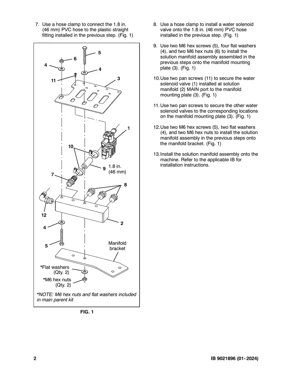
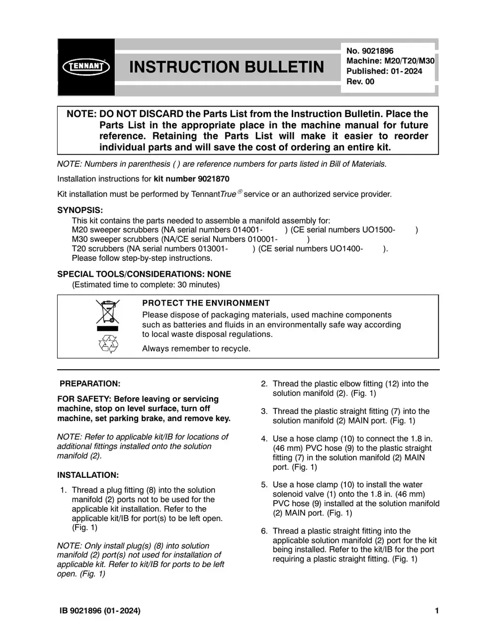
INSTRUCTION B NOTE: DO NOT DISCARD the Parts List Parts List in the appropriate pla reference. Retaining the Parts individual parts and will save the NOTE: Numbers in parenthesis ( ) are reference num Installation instructions for kit number TN4187417 Kit installation must be performed by TennantTruese SYNOPSIS: This kit contains the parts needed to assemble a M20 sweeper scrubbers (NA serial numbers 0140 M30 sweeper scrubbers (NA/CE serial Numbers 0 T20 scrubbers (NA serial numbers 013001- Please follow step-by-step instructions. SPECIAL TOOLS/CONSIDERATIONS: NONE (Estimated time to complete: 30 minutes) PROTECT THE ENVIRONM Please dispose of packaging such as batteries and fluids i to local waste disposal regula Always remember to recycle. PREPARATION: FOR SAFETY: Before leaving or servicing machine, stop on level surface, turn off machine, set parking brake, and remove key. NOTE: Refer to applicable kit/IB for locations of additional fittings installed onto the solution manifold (2). INSTALLATION: 1. Thread a plug fitting (8) into the solution manifold (2) ports not to be used for the applicable kit installation. Refer to the applicable kit/IB for port(s) to be left open. (Fig. 1) NOTE: Only install plug(s) (8) into solution manifold (2) port(s) not used for installation of applicable kit. Refer to kit/IB for ports to be left open. (Fig. 1) IB 9021896 (01- 2024) No. 9021896 Machine: M20/T20/M30 BULLETIN Published: 01- 2024 Rev. 00 from the Instruction Bulletin. Place the ace in the machine manual for future s List will make it easier to reorder e cost of ordering an entire kit. mbers for parts listed in Bill of Materials. ervice or an authorized service provider. manifold assembly for: 001- ) (CE serial numbers UO1500- ) 010001- ) ) (CE serial numbers UO1400- ). MENT g materials, used machine components in an environmentally safe way according ations. . 2. Thread the plastic elbow fitting (12) into the solution manifold (2). (Fig. 1) 3. Thread the plastic straight fitting (7) into the solution manifold (2) MAIN port. (Fig. 1) 4. Use a hose clamp (10) to connect the 1.8 in. (46 mm) PVC hose (9) to the plastic straight fitting (7) in the solution manifold (2) MAIN port. (Fig. 1) 5. Use a hose clamp (10) to install the water solenoid valve (1) onto the 1.8 in. (46 mm) PVC hose (9) installed at the solution manifold (2) MAIN port. (Fig. 1) 6. Thread a plastic straight fitting into the applicable solution manifold (2) port for the kit being installed. Refer to the kit/IB for the port requiring a plastic straight fitting. (Fig. 1) 1
Tennant M20 instruction bulletin 9021896, page 2 of 3
Page 2 of 3
Text of this page
7. Use a hose clamp to connect the 1.8 in. (46 mm) PVC hose to the plastic straight fitting installed in the previous step. (Fig. 1) 5 6 4 4 3 11 1 10 1.8 in. 9 (46 mm) 7 8 12 2 4 Manifold 5 bracket *Flat washers (Qty. 2) *M6 hex nuts (Qty. 2) *NOTE: M6 hex nuts and flat washers included in main parent kit FIG. 1 2 8. Use a hose clamp to install a water solenoid valve onto the 1.8 in. (46 mm) PVC hose installed in the previous step. (Fig. 1) 9. Use two M6 hex screws (5), four flat washers (4), and two M6 hex nuts (6) to install the solution manifold assembly assembled in the previous steps onto the manifold mounting plate (3). (Fig. 1) 10.Use two pan screws (11) to secure the water solenoid valve (1) installed at solution manifold (2) MAIN port to the manifold mounting plate (3). (Fig. 1) 11.Use two pan screws to secure the other water solenoid valves to the corresponding locations on the manifold mounting plate (3). (Fig. 1) 12.Use two M6 hex screws (5), two flat washers (4), and two M6 hex nuts to install the solution manifold assembly in the previous steps onto the manifold bracket. (Fig. 1) 13.Install the solution manifold assembly onto the machine. Refer to the applicable IB for installation instructions. IB 9021896 (01- 2024)
Tennant M20 instruction bulletin 9021896, page 3 of 3
Page 3 of 3
Text of this page
Bill Of Materials For Parts Phantom, Manifold, Aftmkt - TN4187417 Tennant Ref. Part No. Description Qty. 1 TN4042944 Valve, Water, Solenoid [12vdc, BM08/BM08] 1 2 TN4032111 Manifold, Soln 1 3 TN4032116 Plate, Manifold, Mtg 1 4 TN4034136 Washer, Flat, 0.25, Std 6 5 TN4032379 Screw, Hex, M6 X 1.00 X 60, SS, Fl 4 6 TN4041928 Nut, Hex, Lock, M6 X 1.00, NL, SS 2 7 TN4017637 Fitting, Plstc, Str, BM08/PM06 1 8 TN4020528 Fitting, Plug, PM06, Hdpe 3 9 TN5000159 Hose, PVC, Brd, 0.50ID 0.73OD, Bulk, Clr (1.8 in. (46 mm)) 1 10 TN4015366 Clamp, Hose, Worm Drive, 0.31- 0.88D, .31W 2 11 TN4011920 Screw, Pan, 06- X 0.38, F/Plstc 2 12 TN4017647 Fitting, Plstc, E90, BM08/PM06 1 TENNANT COMPANY 10400 Clean Street Eden Prairie, MN 55344- 2650 IB 9021896 (01- 2024) 3

Metering Kit, Detgt, DI

Tennant instruction bulletin 9021850 rev. 00Published 04-2023Kit 9021849

What it’s for: Install a detergent metering kit onto: M20 sweeper scrubbers (NA serial numbers 014001- )(CE serial numbers UO1500- ), M30 sweeper scrubbers (NA/CE serial numbers 010001- ), and T20 scrubbers (NA serial numbers 013001- ) (CE serial numbers UO1400- ).

  • Machines: M20, M30, T20
  • M20 SN 014001 and later
  • Power: gasoline, LPG and diesel
  • Applies to: detergent

Time: 3 hours · Special tools: NONE

Safety warnings (from the bulletin, word for word)

  • WARNING: Lift arm pinch point. Stay clear of hopper lift arms.
  • WARNING: Raised hopper may fall. Engage hopper support pin.
  • FOR SAFETY: Before leaving or servicing machine, stop on level surface, turn off machine, set parking brake, and remove key.
  • WARNING: Always disconnect battery cables from machine before working on electrical components.
  • FOR SAFETY: When servicing machine, avoid contact with battery acid. 1

Tennant says an authorized service provider should install this kit. SES is one: Have SES install this kit.

Parts

Parts for Tennant instruction bulletin 9021850
ItemPart numberQtyDescriptionPrice
TN4018359Old # 90218491Metering Kit, Detgt, DIKitCall for availability 800-440-6723
1TN4032910Old # 10222291Tank, Detgt, Trimmed (All)$341.48/EA
2TN4036929Old # 10118851Cap, Tank (All)$69.10/EA
3TN4039132Old # 209521Screen, Pump (All)$13.70/EA
4TN4039131Old # 209512Fitting, Plstc, E90, Bm06/Bm06 (All)$4.20/EA
6TN4039117Old # 209441Grommet, Pye, 0.37id, F/1.5h, .13 Matl (All)$27.50/EA
7TN4017396Old # 438444Clamp, Hose, Wormdrive, 0.25- 0.62d, .31w (All)$4.20/EA
8TN4016324Old # 732601Pump, Detgt, 14vdc, 150ml/Min 20PSI (All)$792.20/EA
9TN4192827Old # 10337921Plate, Hsng [Fast] (M30)Call for availability 800-440-6723
10TN4035372Old # 242652Screw, Pan, Phl, M4 X 0.70 X 16, SS (All)$3.00/EA
11TN4042888Old # 016833Washer, Flat, 10, SS (All)$2.60/EA
12TN4026576Old # 794841Fitting, Plstc, E90, Bm06/Pm12, Nyl (All)$7.80/EA
14TN4035382Old # 245441Fitting, Plstc, Str, Pm12/Pm12 1.60l (All)$6.20/EA
15TN4013943Old # 760991Screw, Hex, M8 X 1.25 X 25, Fmg (All)$4.00/EA
16TN4028471Old # 3650951Fitting, Plstc, Str, Bm10/Pm12 (M20/T20)$4.20/EA
17TN4018369Old # 697851Fitting, Plstc, E90, Pf12/Pm12 (M20/T20)$11.80/EA
18TN4193627Old # 10251591Bracket, Mtg, Detgt And Spray Wand (M20/T20)$19.70/EA
19TN4041992Old # 097406Screw, Hex, M8 X 1.25 X 20, SS (M20/T20)$3.30/EA
20TN4035242Old # 10172186Washer, Flat, 0.32b 1.00d .12, SS (M20/T20)$3.40/EA
22TN4195605Old # 10213251Bracket, Mtg, Valve (M20/T20)$20.50/EA
23TN4032200Old # 12559141Switch, Rocker [MOM, Off, MOM, Dual LED] (All)$78.81/EA
24TN4015366Old # 543332Clamp, Hose, Worm Drive, 0.31- 0.88d, .31w (All)$5.10/EA

Bulletin PDF: Sign in to view or downloadSign in to download

Installation instructions (11 pages)
Tennant M20 instruction bulletin 9021850, page 1 of 11
Page 1 of 11 SES ref PF-LUX5-Y7HZ‌‌​⁠‍‍‌​‌​‍‌⁠‌⁠​⁠‌‌⁠‌​⁠​‌‌‌‌​​​‌​‍‌​‌‍​​⁠‍⁠​⁠​⁠​‌​​​⁠‌‌⁠​⁠⁠‌
Text of this page
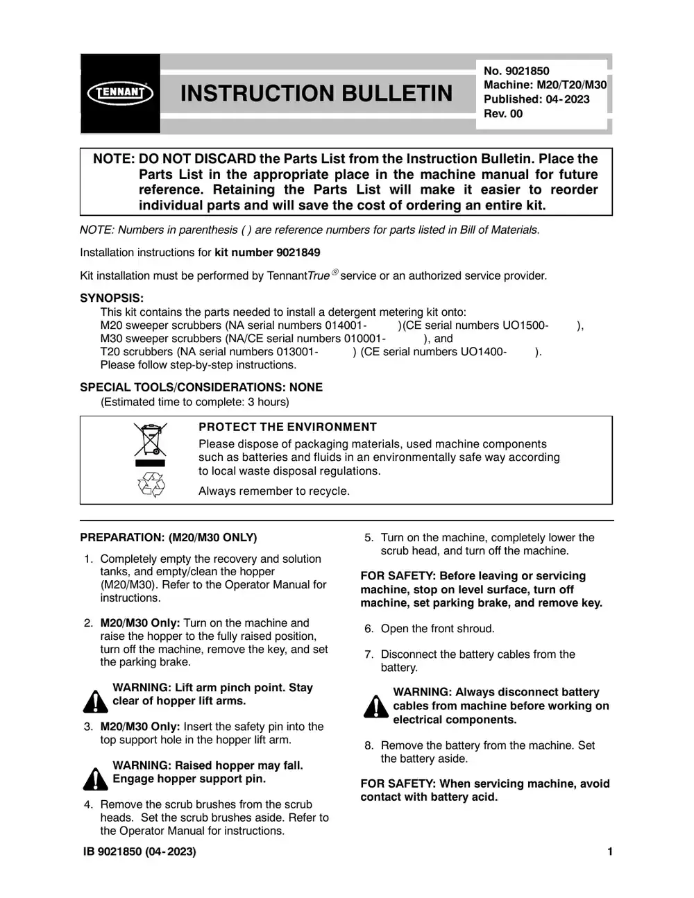
INSTRUCTION B NOTE: DO NOT DISCARD the Parts List Parts List in the appropriate pla reference. Retaining the Parts individual parts and will save the NOTE: Numbers in parenthesis ( ) are reference num Installation instructions for kit number TN4018359 Kit installation must be performed by TennantTruese SYNOPSIS: This kit contains the parts needed to install a dete M20 sweeper scrubbers (NA serial numbers 0140 M30 sweeper scrubbers (NA/CE serial numbers 0 T20 scrubbers (NA serial numbers 013001- Please follow step-by-step instructions. SPECIAL TOOLS/CONSIDERATIONS: NONE (Estimated time to complete: 3 hours) PROTECT THE ENVIRONM Please dispose of packaging such as batteries and fluids i to local waste disposal regula Always remember to recycle. PREPARATION: (M20/M30 ONLY) 1. Completely empty the recovery and solution tanks, and empty/clean the hopper (M20/M30). Refer to the Operator Manual for instructions. 2. M20/M30 Only: Turn on the machine and raise the hopper to the fully raised position, turn off the machine, remove the key, and set the parking brake. WARNING: Lift arm pinch point. Stay clear of hopper lift arms. 3. M20/M30 Only: Insert the safety pin into the top support hole in the hopper lift arm. WARNING: Raised hopper may fall. Engage hopper support pin. 4. Remove the scrub brushes from the scrub heads. Set the scrub brushes aside. Refer to the Operator Manual for instructions. IB 9021850 (04- 2023) No. 9021850 Machine: M20/T20/M30 BULLETIN Published: 04- 2023 Rev. 00 from the Instruction Bulletin. Place the ace in the machine manual for future s List will make it easier to reorder e cost of ordering an entire kit. mbers for parts listed in Bill of Materials. ervice or an authorized service provider. ergent metering kit onto: 001- )(CE serial numbers UO1500- ), 010001- ), and ) (CE serial numbers UO1400- ). MENT g materials, used machine components in an environmentally safe way according ations. . 5. Turn on the machine, completely lower the scrub head, and turn off the machine. FOR SAFETY: Before leaving or servicing machine, stop on level surface, turn off machine, set parking brake, and remove key. 6. Open the front shroud. 7. Disconnect the battery cables from the battery. WARNING: Always disconnect battery cables from machine before working on electrical components. 8. Remove the battery from the machine. Set the battery aside. FOR SAFETY: When servicing machine, avoid contact with battery acid. 1
Tennant M20 instruction bulletin 9021850, page 2 of 11
Page 2 of 11
Text of this page
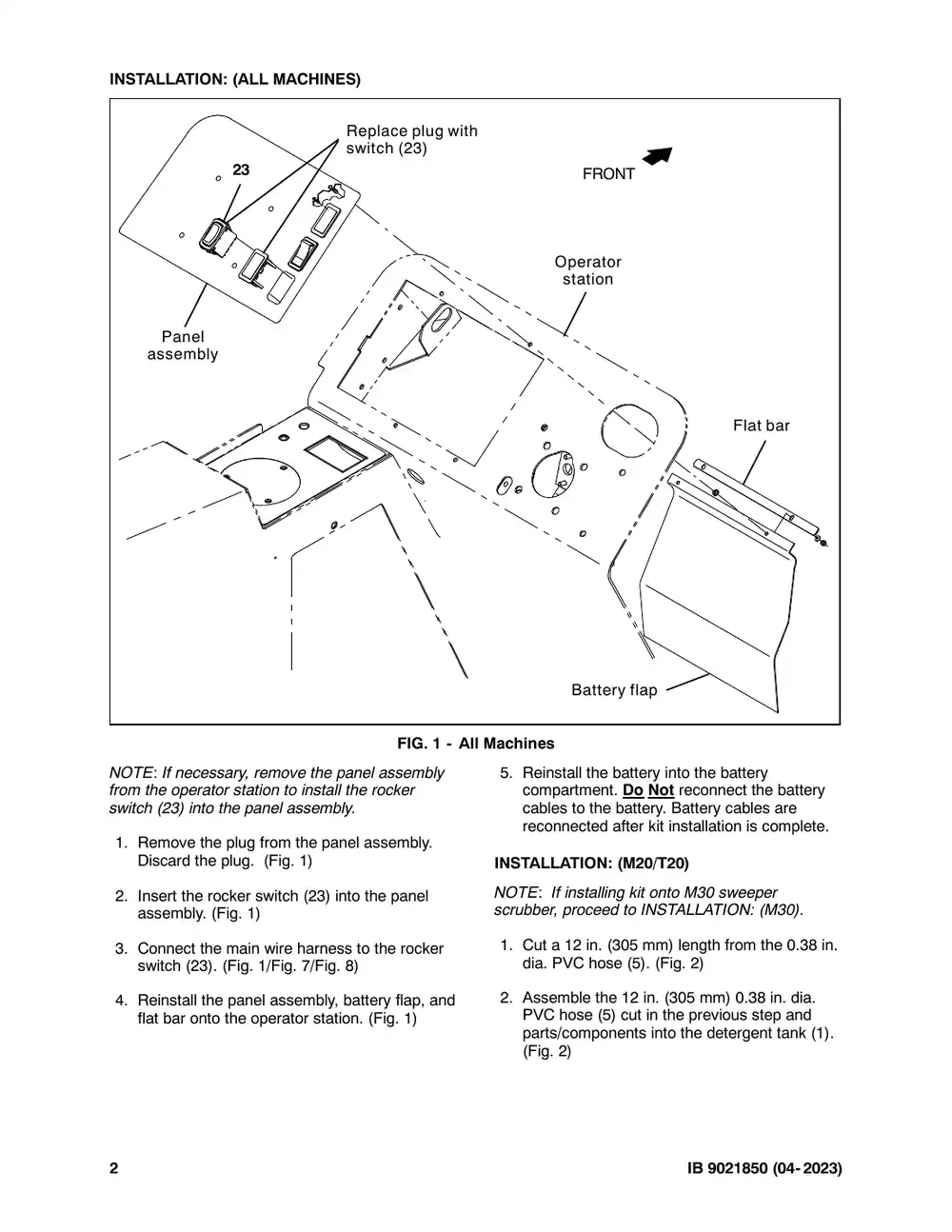
INSTALLATION: (ALL MACHINES) Replace plug with switch (23) 23 23 Panel assembly FIG. 1 - All NOTE: If necessary, remove the panel assembly from the operator station to install the rocker switch (23) into the panel assembly. 1. Remove the plug from the panel assembly. Discard the plug. (Fig. 1) 2. Insert the rocker switch (23) into the panel assembly. (Fig. 1) 3. Connect the main wire harness to the rocker switch (23). (Fig. 1/Fig. 7/Fig. 8) 4. Reinstall the panel assembly, battery flap, and flat bar onto the operator station. (Fig. 1) 2 FRONT Operator station Flat bar Battery flap l Machines 5. Reinstall the battery into the battery compartment. Do Not reconnect the battery cables to the battery. Battery cables are reconnected after kit installation is complete. INSTALLATION: (M20/T20) NOTE: If installing kit onto M30 sweeper scrubber, proceed to INSTALLATION: (M30). 1. Cut a 12 in. (305 mm) length from the 0.38 in. dia. PVC hose (5). (Fig. 2) 2. Assemble the 12 in. (305 mm) 0.38 in. dia. PVC hose (5) cut in the previous step and parts/components into the detergent tank (1). (Fig. 2) IB 9021850 (04- 2023)
Tennant M20 instruction bulletin 9021850, page 3 of 11
Page 3 of 11
Text of this page
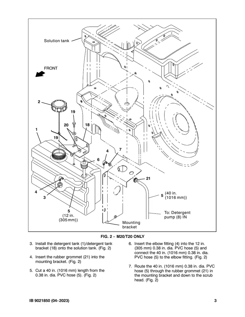
Solution tank FRONT 2 19 20 18 1 19 7 4 6 4 3 5 (12 in. (305 mm)) M b FIG. 2 - M20 3. Install the detergent tank (1)/detergent tank bracket (18) onto the solution tank. (Fig. 2) 4. Insert the rubber grommet (21) into the mounting bracket. (Fig. 2) 5. Cut a 40 in. (1016 mm) length from the 0.38 in. dia. PVC hose (5). (Fig. 2) IB 9021850 (04- 2023) 21 (40 in. 5 (1016 mm)) To: Detergent pump (8) IN Mounting bracket 0/T20 ONLY 6. Insert the elbow fitting (4) into the 12 in. (305 mm) 0.38 in. dia. PVC hose (5) and connect the 40 in. (1016 mm) 0.38 in. dia. PVC hose (5) to the elbow fitting. (Fig. 2) 7. Route the 40 in. (1016 mm) 0.38 in. dia. PVC hose (5) through the rubber grommet (21) in the mounting bracket and down to the scrub head. (Fig. 2) 3
Tennant M20 instruction bulletin 9021850, page 4 of 11
Page 4 of 11
Text of this page
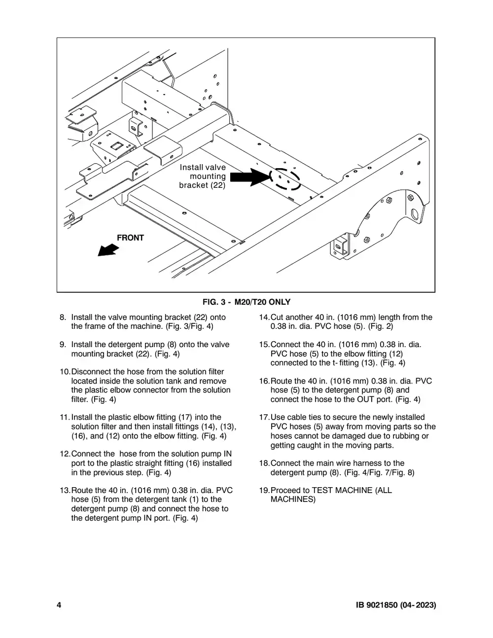
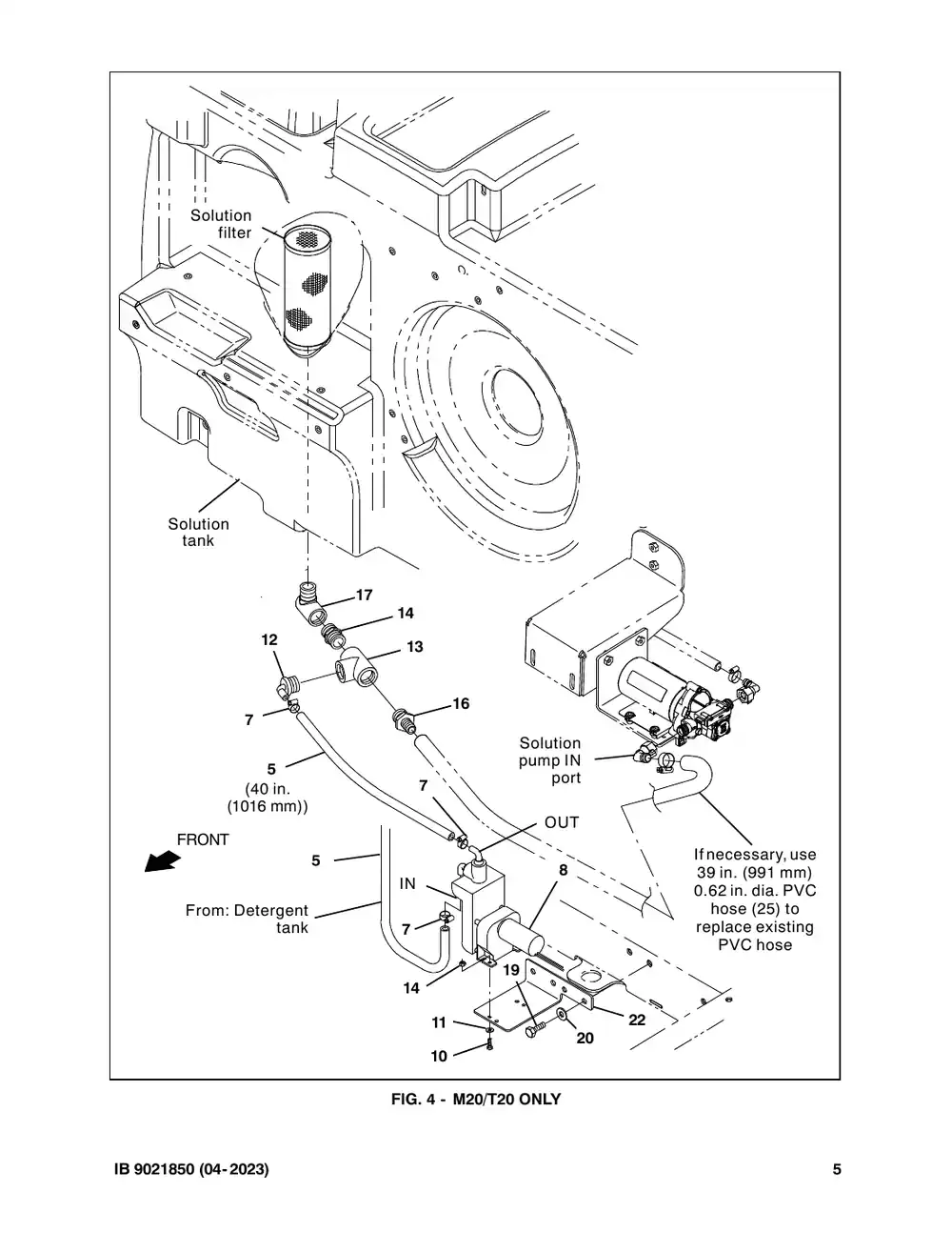
Install valve mounting bracket (22) FRONT FIG. 3 - M20 8. Install the valve mounting bracket (22) onto the frame of the machine. (Fig. 3/Fig. 4) 9. Install the detergent pump (8) onto the valve mounting bracket (22). (Fig. 4) 10.Disconnect the hose from the solution filter located inside the solution tank and remove the plastic elbow connector from the solution filter. (Fig. 4) 11.Install the plastic elbow fitting (17) into the solution filter and then install fittings (14), (13), (16), and (12) onto the elbow fitting. (Fig. 4) 12.Connect the hose from the solution pump IN port to the plastic straight fitting (16) installed in the previous step. (Fig. 4) 13.Route the 40 in. (1016 mm) 0.38 in. dia. PVC hose (5) from the detergent tank (1) to the detergent pump (8) and connect the hose to the detergent pump IN port. (Fig. 4) 4 0/T20 ONLY 14.Cut another 40 in. (1016 mm) length from the 0.38 in. dia. PVC hose (5). (Fig. 2) 15.Connect the 40 in. (1016 mm) 0.38 in. dia. PVC hose (5) to the elbow fitting (12) connected to the t- fitting (13). (Fig. 4) 16.Route the 40 in. (1016 mm) 0.38 in. dia. PVC hose (5) to the detergent pump (8) and connect the hose to the OUT port. (Fig. 4) 17.Use cable ties to secure the newly installed PVC hoses (5) away from moving parts so the hoses cannot be damaged due to rubbing or getting caught in the moving parts. 18.Connect the main wire harness to the detergent pump (8). (Fig. 4/Fig. 7/Fig. 8) 19.Proceed to TEST MACHINE (ALL MACHINES) IB 9021850 (04- 2023)
Tennant M20 instruction bulletin 9021850, page 5 of 11
Page 5 of 11
Text of this page
Solution filter Solution tank 17 14 12 13 16 7 5 (40 in. 7 (1016 mm)) FRONT 5 IN From: Detergent tank 7 14 11 10 FIG. 4 - M20 IB 9021850 (04- 2023) Solution pump IN port OUT If necessary, use 8 39 in. (991 mm) 0.62 in. dia. PVC hose (25) to replace existing PVC hose 19 22 20 0/T20 ONLY 5
Tennant M20 instruction bulletin 9021850, page 6 of 11
Page 6 of 11
Text of this page
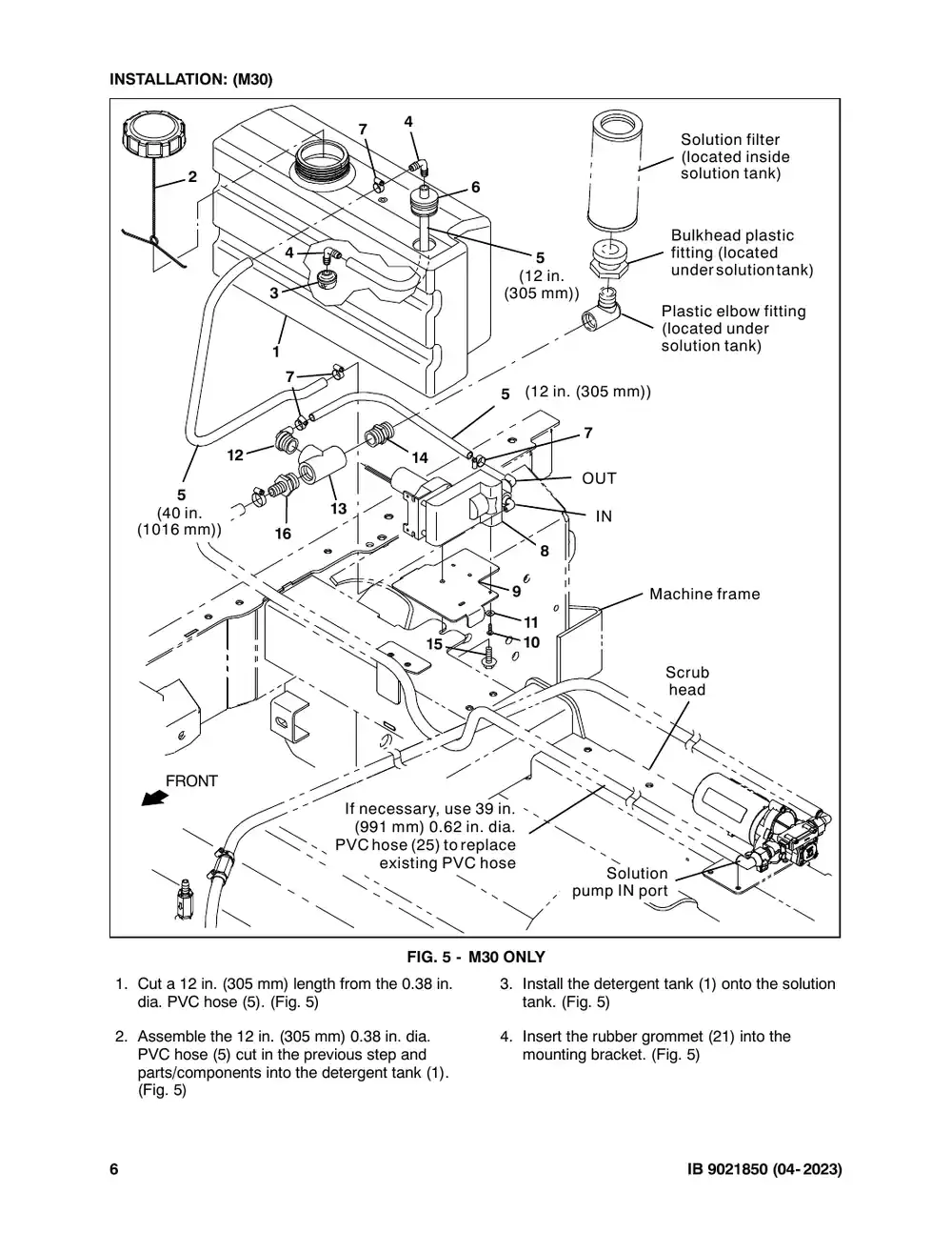
INSTALLATION: (M30) 4 7 7 2 6 4 3 1 7 12 14 5 (40 in. 13 (1016 mm)) 16 15 FRONT If necessary, use 3 (991 mm) 0.62 in PVC hose (25) to rep existing PVC FIG. 5 - M 1. Cut a 12 in. (305 mm) length from the 0.38 in. dia. PVC hose (5). (Fig. 5) 2. Assemble the 12 in. (305 mm) 0.38 in. dia. PVC hose (5) cut in the previous step and parts/components into the detergent tank (1). (Fig. 5) 6 Solution filter (located inside solution tank) 6 Bulkhead plastic fitting (located 5 undersolutiontank) (12 in. (305 mm)) Plastic elbow fitting (located under solution tank) 5 (12 in. (305 mm)) 7 OUT IN 8 9 Machine frame 11 10 Scrub head 39 in. n. dia. place hose Solution pump IN port M30 ONLY 3. Install the detergent tank (1) onto the solution tank. (Fig. 5) 4. Insert the rubber grommet (21) into the mounting bracket. (Fig. 5) IB 9021850 (04- 2023)
Tennant M20 instruction bulletin 9021850, page 7 of 11
Page 7 of 11
Text of this page
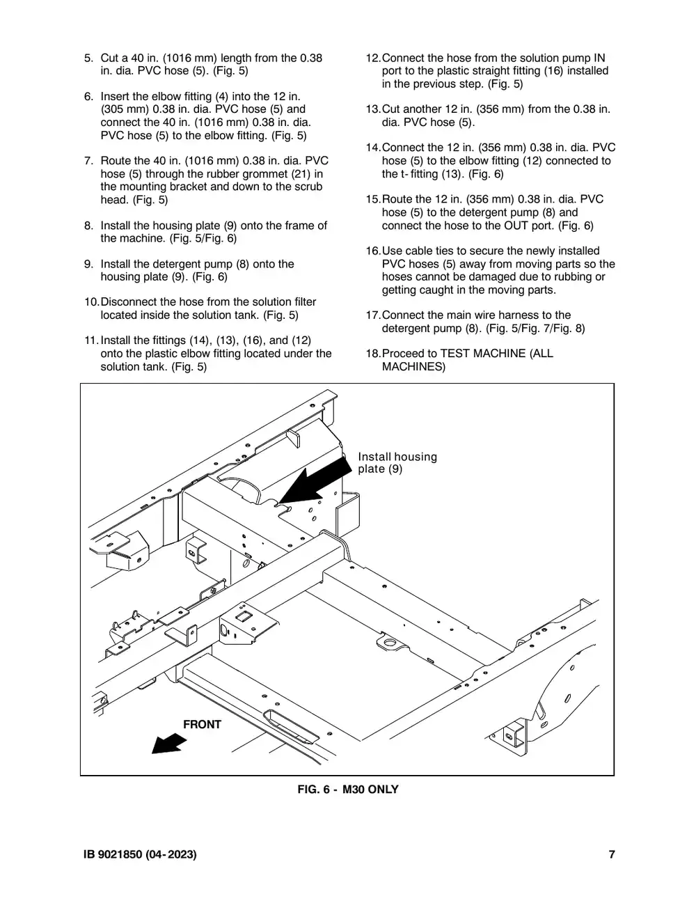
5. Cut a 40 in. (1016 mm) length from the 0.38 in. dia. PVC hose (5). (Fig. 5) 6. Insert the elbow fitting (4) into the 12 in. (305 mm) 0.38 in. dia. PVC hose (5) and connect the 40 in. (1016 mm) 0.38 in. dia. PVC hose (5) to the elbow fitting. (Fig. 5) 7. Route the 40 in. (1016 mm) 0.38 in. dia. PVC hose (5) through the rubber grommet (21) in the mounting bracket and down to the scrub head. (Fig. 5) 8. Install the housing plate (9) onto the frame of the machine. (Fig. 5/Fig. 6) 9. Install the detergent pump (8) onto the housing plate (9). (Fig. 6) 10.Disconnect the hose from the solution filter located inside the solution tank. (Fig. 5) 11.Install the fittings (14), (13), (16), and (12) onto the plastic elbow fitting located under the solution tank. (Fig. 5) FRONT FIG. 6 - M IB 9021850 (04- 2023) 12.Connect the hose from the solution pump IN port to the plastic straight fitting (16) installed in the previous step. (Fig. 5) 13.Cut another 12 in. (356 mm) from the 0.38 in. dia. PVC hose (5). 14.Connect the 12 in. (356 mm) 0.38 in. dia. PVC hose (5) to the elbow fitting (12) connected to the t- fitting (13). (Fig. 6) 15.Route the 12 in. (356 mm) 0.38 in. dia. PVC hose (5) to the detergent pump (8) and connect the hose to the OUT port. (Fig. 6) 16.Use cable ties to secure the newly installed PVC hoses (5) away from moving parts so the hoses cannot be damaged due to rubbing or getting caught in the moving parts. 17.Connect the main wire harness to the detergent pump (8). (Fig. 5/Fig. 7/Fig. 8) 18.Proceed to TEST MACHINE (ALL MACHINES) Install housing plate (9) M30 ONLY 7
Tennant M20 instruction bulletin 9021850, page 8 of 11
Page 8 of 11
Text of this page
TEST MACHINE: (ALL MACHINES) 1. Reconnect the battery cables to the battery. 2. M20/M30 Only: Turn on the machine, remove the hopper support pin, and lower the hopper. Refer to the Operator Manual for additional instructions and safety information. WARNING: Lift arm pinch point. Stay clear of hopper lift arms. 3. Raise the scrub head and turn off the machine. 4. Reinstall the brushes into the scrub head. Refer to the Operator Manual for instructions. 8 5. Fill the solution tank with cool clean water. Refer to the Operator Manual for instructions. 6. Fill the detergent tank (1) with detergent and install the tank cap (2) onto the detergent tank. 7. Start and test the machine. Operate the machine over a short distance and press the detergent metering switch to dispense solution. Observe newly installed parts to ensure there are no leaks around hoses/ fittings. Repair leaks. If the detergent metering is not functioning, troubleshoot the detergent metering electrical circuit. Repair electrical issues as necessary. IB 9021850 (04- 2023)
Tennant M20 instruction bulletin 9021850, page 9 of 11
Page 9 of 11
Text of this page
FIG. 7 IB 9021850 (04- 2023) 9
Tennant M20 instruction bulletin 9021850, page 10 of 11
Page 10 of 11
Text of this page
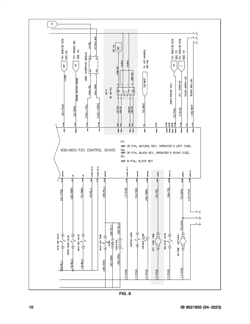
FIG. 8 10 IB 9021850 (04- 2023)
Tennant M20 instruction bulletin 9021850, page 11 of 11
Page 11 of 11
Text of this page
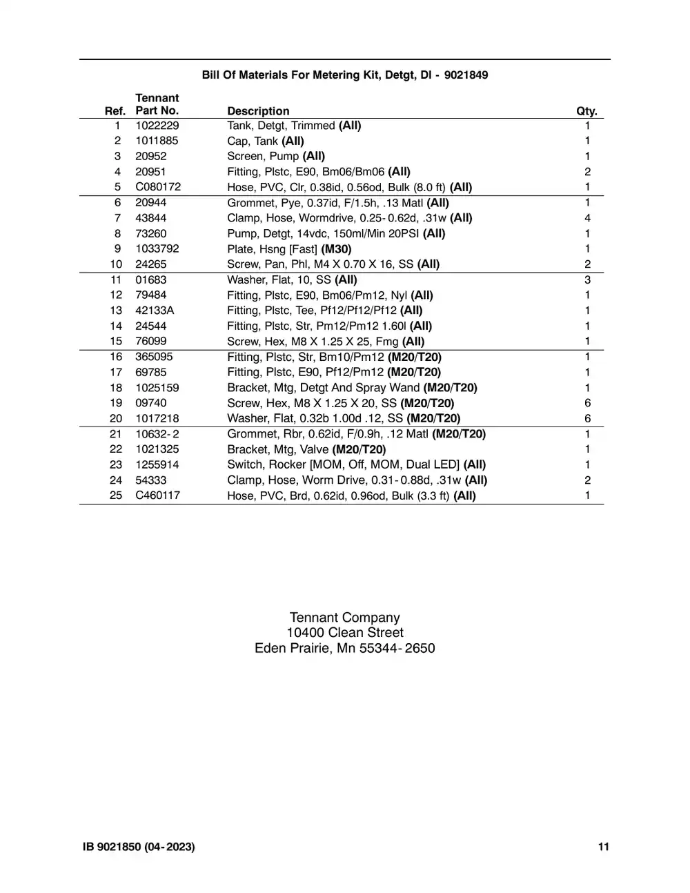
Bill Of Materials For Metering Kit, Detgt, DI - TN4018359 Tennant Ref. Part No. Description Qty. 1 TN4032910 Tank, Detgt, Trimmed (All) 1 2 TN4036929 Cap, Tank (All) 1 3 TN4039132 Screen, Pump (All) 1 4 TN4039131 Fitting, Plstc, E90, Bm06/Bm06 (All) 2 5 C080172 Hose, PVC, Clr, 0.38id, 0.56od, Bulk (8.0 ft) (All) 1 6 TN4039117 Grommet, Pye, 0.37id, F/1.5h, .13 Matl (All) 1 7 TN4017396 Clamp, Hose, Wormdrive, 0.25- 0.62d, .31w (All) 4 8 TN4016324 Pump, Detgt, 14vdc, 150ml/Min 20PSI (All) 1 9 TN4192827 Plate, Hsng [Fast] (M30) 1 10 TN4035372 Screw, Pan, Phl, M4 X 0.70 X 16, SS (All) 2 11 TN4042888 Washer, Flat, 10, SS (All) 3 12 TN4026576 Fitting, Plstc, E90, Bm06/Pm12, Nyl (All) 1 13 42133A Fitting, Plstc, Tee, Pf12/Pf12/Pf12 (All) 1 14 TN4035382 Fitting, Plstc, Str, Pm12/Pm12 1.60l (All) 1 15 TN4013943 Screw, Hex, M8 X 1.25 X 25, Fmg (All) 1 16 TN4028471 Fitting, Plstc, Str, Bm10/Pm12 (M20/T20) 1 17 TN4018369 Fitting, Plstc, E90, Pf12/Pm12 (M20/T20) 1 18 TN4193627 Bracket, Mtg, Detgt And Spray Wand (M20/T20) 1 19 TN4041992 Screw, Hex, M8 X 1.25 X 20, SS (M20/T20) 6 20 TN4035242 Washer, Flat, 0.32b 1.00d .12, SS (M20/T20) 6 21 10632- 2 Grommet, Rbr, 0.62id, F/0.9h, .12 Matl (M20/T20) 1 22 TN4195605 Bracket, Mtg, Valve (M20/T20) 1 23 TN4032200 Switch, Rocker [MOM, Off, MOM, Dual LED] (All) 1 24 TN4015366 Clamp, Hose, Worm Drive, 0.31- 0.88d, .31w (All) 2 25 C460117 Hose, PVC, Brd, 0.62id, 0.96od, Bulk (3.3 ft) (All) 1 Tennant Company 10400 Clean Street Eden Prairie, Mn 55344- 2650 IB 9021850 (04- 2023) 11

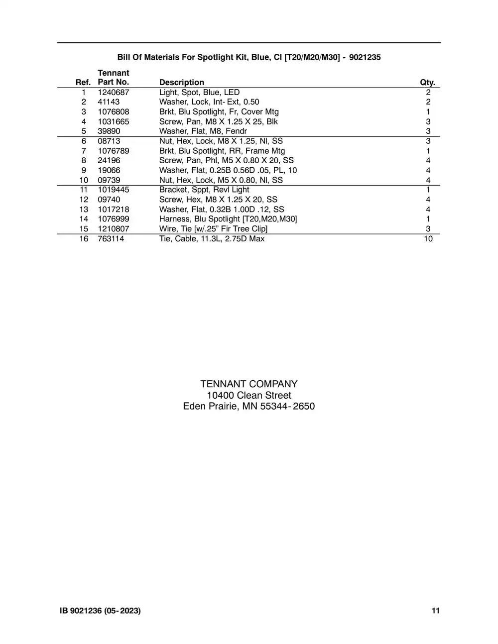
Spotlight Kit, Blue, CI [T20/M20/M30]

Tennant instruction bulletin 9021236 rev. 00Published 05-2023Kit 9021235

What it’s for: Install the blue spotlight kit on M20/M30 sweeper scrubbers and T20 scrubbers.

  • Machines: M20, M30, T20
  • M20: all
  • Power: gasoline, LPG and diesel
  • Applies to: lights

Time: 3 hours · Special tools: NONE

Safety warnings (from the bulletin, word for word)

  • FOR SAFETY: Before leaving or servicing machine, stop on level surface, turn off machine, set parking brake, and remove key.
  • WARNING: Lift arm pinch point. Stay clear of hopper lift arms.
  • WARNING: Raised hopper may fall. Engage hopper support pin.
  • WARNING: Always disconnect battery cables from machine before working on electrical components. 1

Tennant says an authorized service provider should install this kit. SES is one: Have SES install this kit.

Parts

Parts for Tennant instruction bulletin 9021236
ItemPart numberQtyDescriptionPrice
TN4022024Old # 90212351Spotlight Kit, Blue, CI [T20/M20/M30]Kit$868.40/EA
1TN4033715Old # 12406872Light, Spot, Blue, LED$562.40/EA
2TN4016789Old # 411432Washer, Lock, Int- Ext, 0.50$3.10/EA
3TN4042916Old # 10768081Brkt, Blu Spotlight, Fr, Cover Mtg$56.60/EA
4TN4032093Old # 10316653Screw, Pan, M8 X 1.25 X 25, Blk$3.40/EA
5TN4016551Old # 398903Washer, Flat, M8, Fendr$4.10/EA
6TN4041929Old # 087133Nut, Hex, Lock, M8 X 1.25, Nl, SS$3.30/EA
7TN4042910Old # 10767891Brkt, Blu Spotlight, RR, Frame Mtg$22.32/EA
8TN4035367Old # 241964Screw, Pan, Phl, M5 X 0.80 X 20, SS$3.20/EA
9TN4042244Old # 190664Washer, Flat, 0.25B 0.56D .05, PL, 10$2.50/EA
10TN4041991Old # 097394Nut, Hex, Lock, M5 X 0.80, Nl, SS$3.30/EA
11TN4035919Old # 10194451Bracket, Sppt, Revl Light$55.20/EA
12TN4041992Old # 097404Screw, Hex, M8 X 1.25 X 20, SS$3.30/EA
13TN4035242Old # 10172184Washer, Flat, 0.32B 1.00D .12, SS$3.40/EA
14TN4042993Old # 10769991Harness, Blu Spotlight [T20,M20,M30]$147.76/EA
15TN4038889Old # 12108073Wire, Tie [w/.25” Fir Tree Clip]$1.90/EA
16TN4011908Old # 76311410Tie, Cable, 11.3L, 2.75D Max$3.30/EA

Bulletin PDF: Sign in to view or downloadSign in to download

Installation instructions (11 pages)
Tennant M20 instruction bulletin 9021236, page 1 of 11
Page 1 of 11 SES ref PF-RMPT-JPRO‌‌​⁠‍‍‌​‌​‍‌⁠‌⁠​⁠‌‌⁠⁠​‍⁠​⁠​​​​​‌​‍‌​⁠​⁠‌⁠‌‌​‍⁠​⁠‌​‍​⁠‍⁠​⁠​​⁠
Text of this page
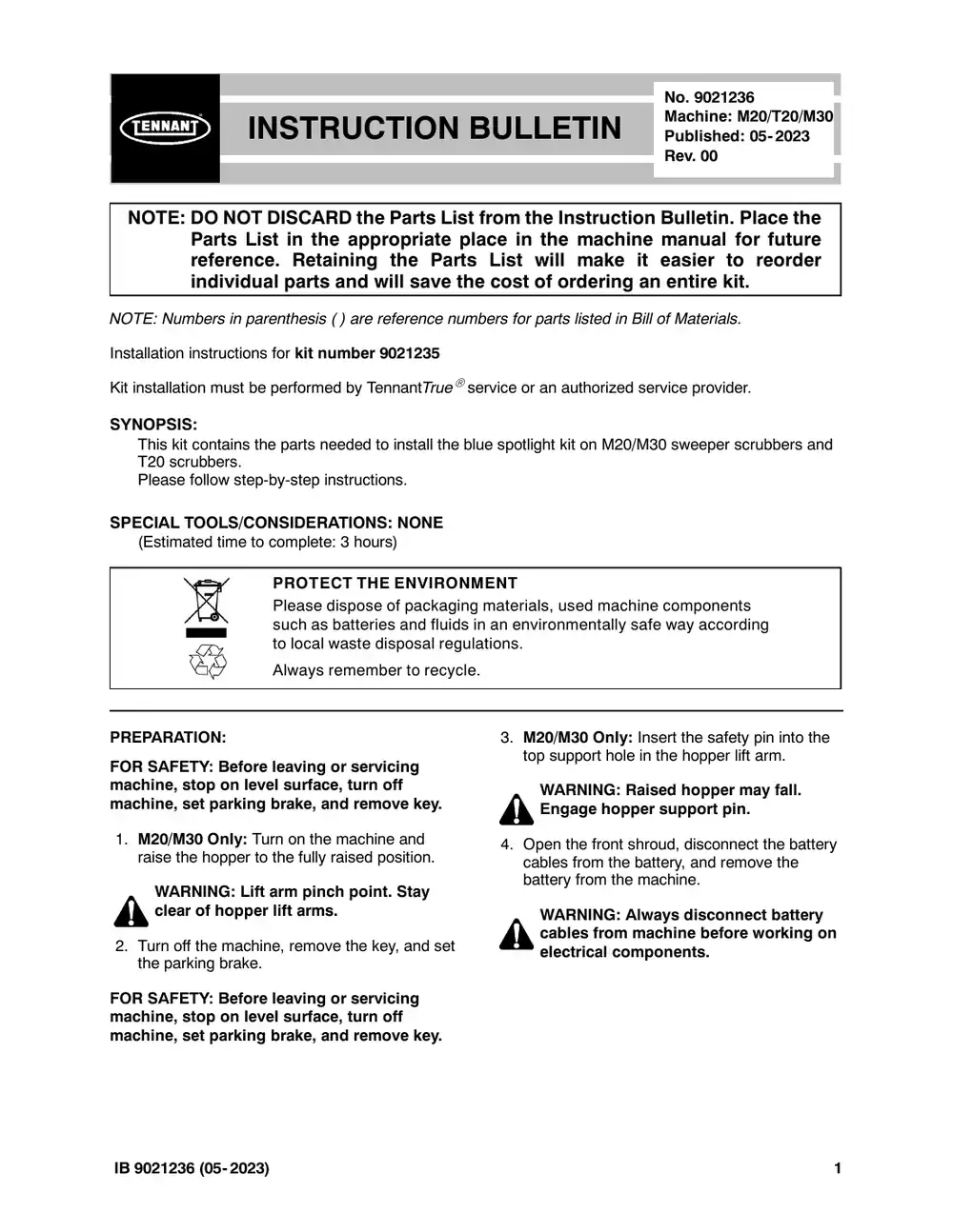
INSTRUCTION B NOTE: DO NOT DISCARD the Parts List Parts List in the appropriate pla reference. Retaining the Parts individual parts and will save the NOTE: Numbers in parenthesis ( ) are reference num Installation instructions for kit number TN4022024 Kit installation must be performed by TennantTruese SYNOPSIS: This kit contains the parts needed to install the blu T20 scrubbers. Please follow step-by-step instructions. SPECIAL TOOLS/CONSIDERATIONS: NONE (Estimated time to complete: 3 hours) PROTECT THE ENVIRONM Please dispose of packaging such as batteries and fluids i to local waste disposal regula Always remember to recycle. PREPARATION: FOR SAFETY: Before leaving or servicing machine, stop on level surface, turn off machine, set parking brake, and remove key. 1. M20/M30 Only: Turn on the machine and raise the hopper to the fully raised position. WARNING: Lift arm pinch point. Stay clear of hopper lift arms. 2. Turn off the machine, remove the key, and set the parking brake. FOR SAFETY: Before leaving or servicing machine, stop on level surface, turn off machine, set parking brake, and remove key. IB 9021236 (05- 2023) No. 9021236 Machine: M20/T20/M30 BULLETIN Published: 05- 2023 Rev. 00 from the Instruction Bulletin. Place the ace in the machine manual for future s List will make it easier to reorder e cost of ordering an entire kit. mbers for parts listed in Bill of Materials. ervice or an authorized service provider. ue spotlight kit on M20/M30 sweeper scrubbers and MENT g materials, used machine components in an environmentally safe way according ations. . 3. M20/M30 Only: Insert the safety pin into the top support hole in the hopper lift arm. WARNING: Raised hopper may fall. Engage hopper support pin. 4. Open the front shroud, disconnect the battery cables from the battery, and remove the battery from the machine. WARNING: Always disconnect battery cables from machine before working on electrical components. 1
Tennant M20 instruction bulletin 9021236, page 2 of 11
Page 2 of 11
Text of this page
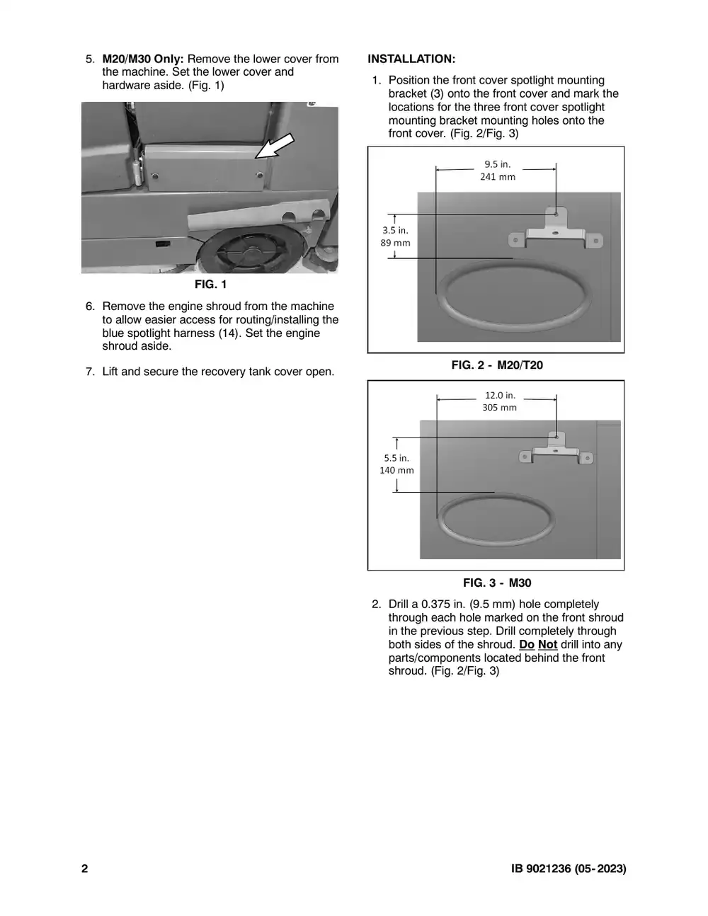
5. M20/M30 Only: Remove the lower cover from the machine. Set the lower cover and hardware aside. (Fig. 1) FIG. 1 6. Remove the engine shroud from the machine to allow easier access for routing/installing the blue spotlight harness (14). Set the engine shroud aside. 7. Lift and secure the recovery tank cover open. 2 INSTALLATION: 1. Position the front cover spotlight mounting bracket (3) onto the front cover and mark the locations for the three front cover spotlight mounting bracket mounting holes onto the front cover. (Fig. 2/Fig. 3) FIG. 2 - M20/T20 FIG. 3 - M30 2. Drill a 0.375 in. (9.5 mm) hole completely through each hole marked on the front shroud in the previous step. Drill completely through both sides of the shroud. Do Not drill into any parts/components located behind the front shroud. (Fig. 2/Fig. 3) IB 9021236 (05- 2023)
Tennant M20 instruction bulletin 9021236, page 3 of 11
Page 3 of 11
Text of this page
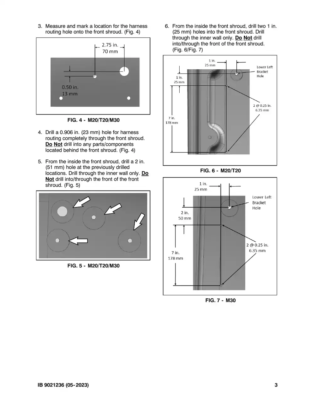
3. Measure and mark a location for the harness routing hole onto the front shroud. (Fig. 4) FIG. 4 - M20/T20/M30 4. Drill a 0.906 in. (23 mm) hole for harness routing completely through the front shroud. Do Not drill into any parts/components located behind the front shroud. (Fig. 4) 5. From the inside the front shroud, drill a 2 in. (51 mm) hole at the previously drilled locations. Drill through the inner wall only. Do Not drill into/through the front of the front shroud. (Fig. 5) FIG. 5 - M20/T20/M30 IB 9021236 (05- 2023) 6. From the inside the front shroud, drill two 1 in. (25 mm) holes into the front shroud. Drill through the inner wall only. Do Not drill into/through the front of the front shroud. (Fig. 6/Fig. 7) FIG. 6 - M20/T20 FIG. 7 - M30 3
Tennant M20 instruction bulletin 9021236, page 4 of 11
Page 4 of 11
Text of this page
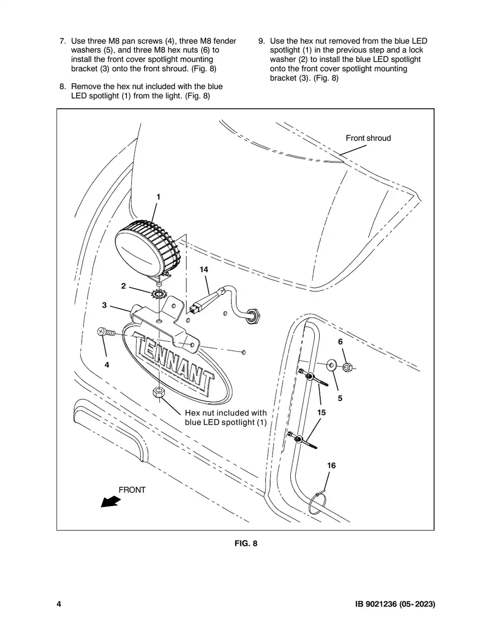
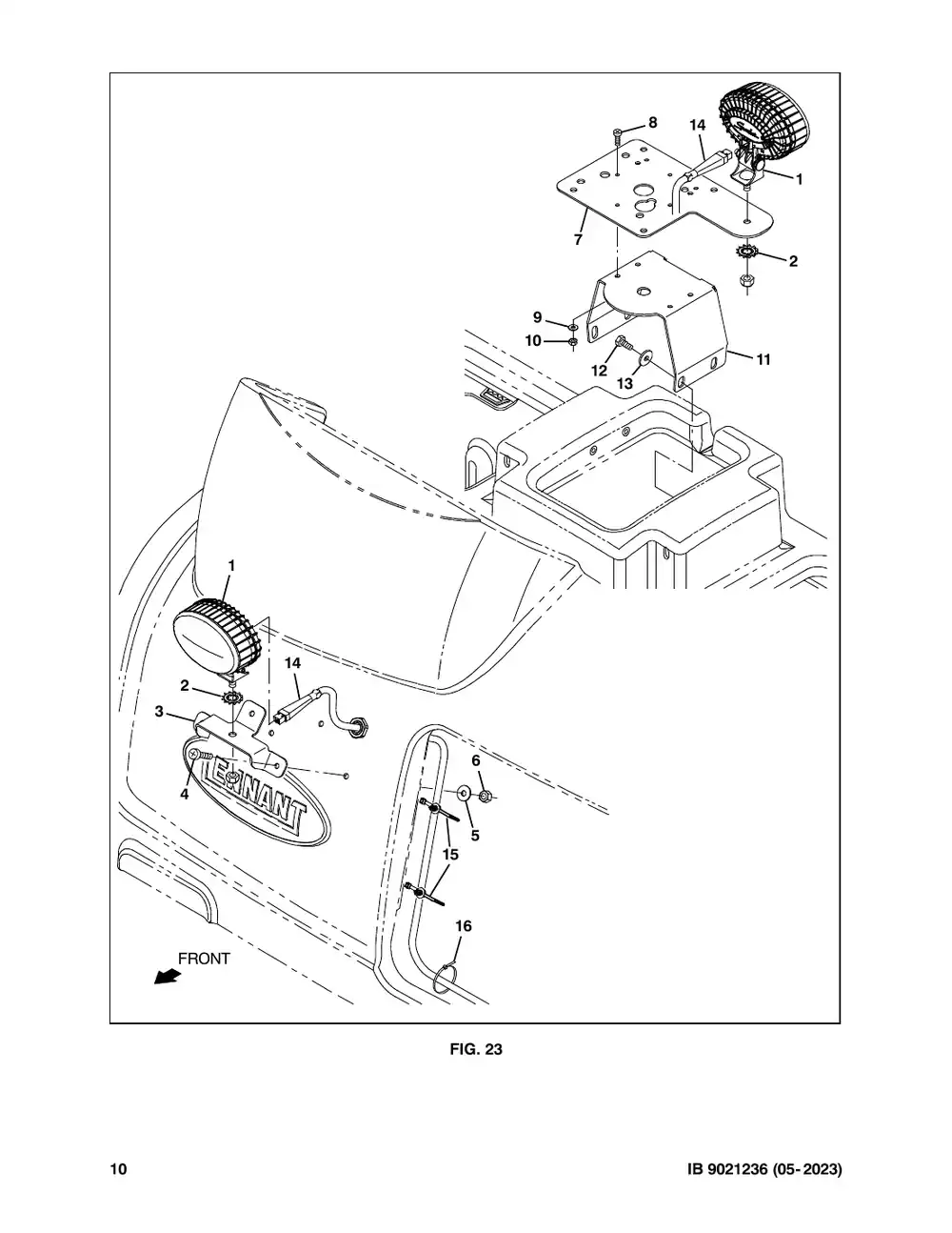
7. Use three M8 pan screws (4), three M8 fender washers (5), and three M8 hex nuts (6) to install the front cover spotlight mounting bracket (3) onto the front shroud. (Fig. 8) 8. Remove the hex nut included with the blue LED spotlight (1) from the light. (Fig. 8) 1 14 2 3 4 Hex nut included blue LED spotlig FRONT FIG 4 9. Use the hex nut removed from the blue LED spotlight (1) in the previous step and a lock washer (2) to install the blue LED spotlight onto the front cover spotlight mounting bracket (3). (Fig. 8) Front shroud 6 5 d with 15 ght (1) 16 G. 8 IB 9021236 (05- 2023)
Tennant M20 instruction bulletin 9021236, page 5 of 11
Page 5 of 11
Text of this page
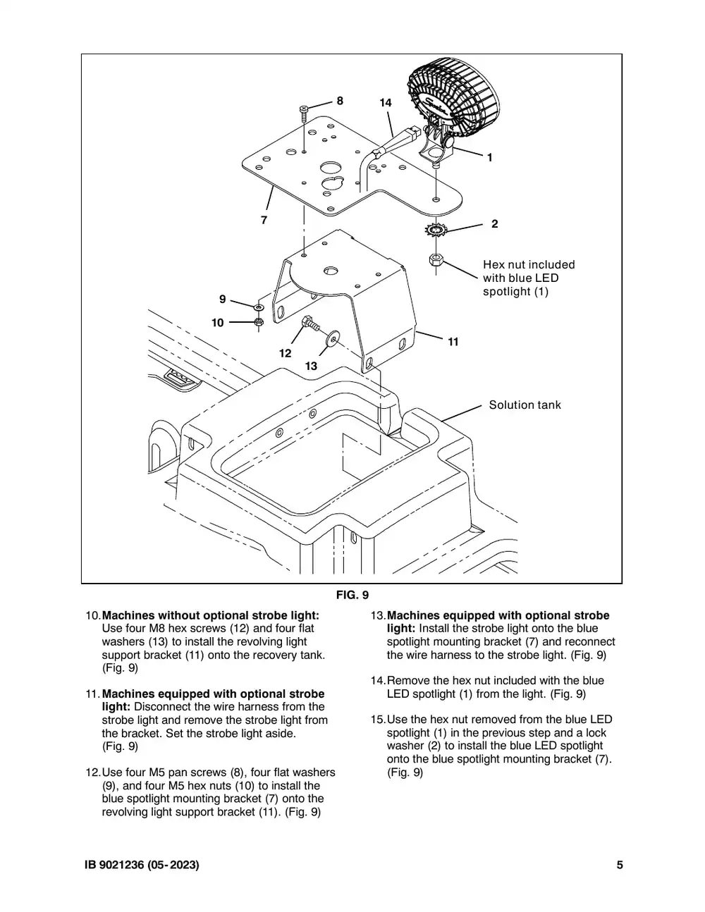
8 8 7 9 10 12 13 FIG 10.Machines without optional strobe light: Use four M8 hex screws (12) and four flat washers (13) to install the revolving light support bracket (11) onto the recovery tank. (Fig. 9) 11.Machines equipped with optional strobe light: Disconnect the wire harness from the strobe light and remove the strobe light from the bracket. Set the strobe light aside. (Fig. 9) 12.Use four M5 pan screws (8), four flat washers (9), and four M5 hex nuts (10) to install the blue spotlight mounting bracket (7) onto the revolving light support bracket (11). (Fig. 9) IB 9021236 (05- 2023) 14 1 2 Hex nut included with blue LED spotlight (1) 11 Solution tank G. 9 13.Machines equipped with optional strobe light: Install the strobe light onto the blue spotlight mounting bracket (7) and reconnect the wire harness to the strobe light. (Fig. 9) 14.Remove the hex nut included with the blue LED spotlight (1) from the light. (Fig. 9) 15.Use the hex nut removed from the blue LED spotlight (1) in the previous step and a lock washer (2) to install the blue LED spotlight onto the blue spotlight mounting bracket (7). (Fig. 9) 5
Tennant M20 instruction bulletin 9021236, page 6 of 11
Page 6 of 11
Text of this page
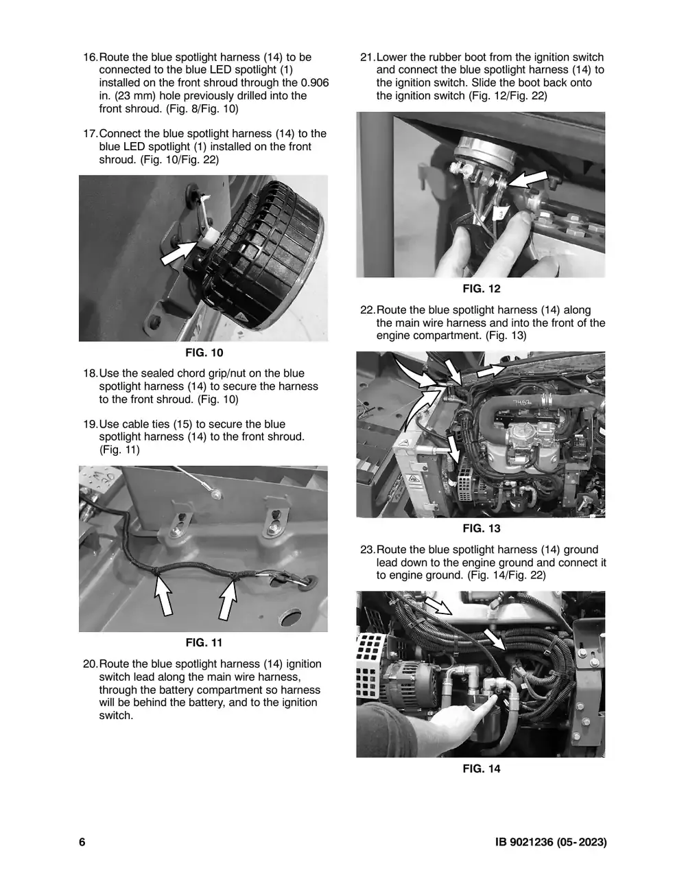
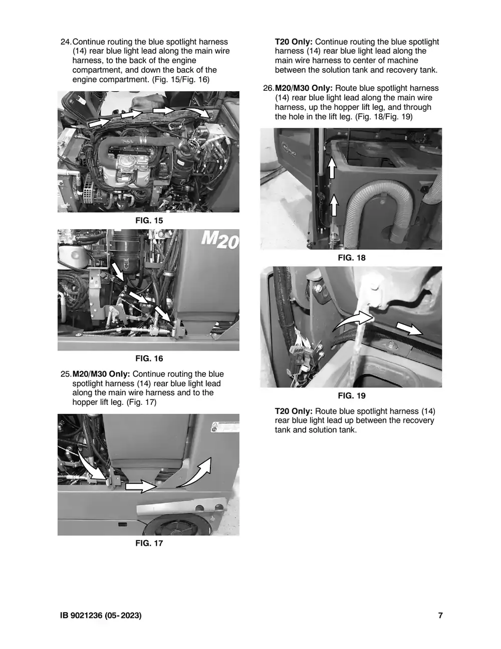
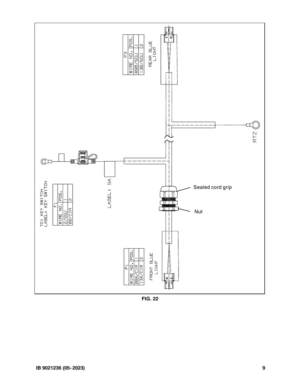
16.Route the blue spotlight harness (14) to be connected to the blue LED spotlight (1) installed on the front shroud through the 0.906 in. (23 mm) hole previously drilled into the front shroud. (Fig. 8/Fig. 10) 17.Connect the blue spotlight harness (14) to the blue LED spotlight (1) installed on the front shroud. (Fig. 10/Fig. 22) FIG. 10 18.Use the sealed chord grip/nut on the blue spotlight harness (14) to secure the harness to the front shroud. (Fig. 10) 19.Use cable ties (15) to secure the blue spotlight harness (14) to the front shroud. (Fig. 11) FIG. 11 20.Route the blue spotlight harness (14) ignition switch lead along the main wire harness, through the battery compartment so harness will be behind the battery, and to the ignition switch. 6 21.Lower the rubber boot from the ignition switch and connect the blue spotlight harness (14) to the ignition switch. Slide the boot back onto the ignition switch (Fig. 12/Fig. 22) FIG. 12 22.Route the blue spotlight harness (14) along the main wire harness and into the front of the engine compartment. (Fig. 13) FIG. 13 23.Route the blue spotlight harness (14) ground lead down to the engine ground and connect it to engine ground. (Fig. 14/Fig. 22) FIG. 14 IB 9021236 (05- 2023)
Tennant M20 instruction bulletin 9021236, page 7 of 11
Page 7 of 11
Text of this page
24.Continue routing the blue spotlight harness (14) rear blue light lead along the main wire harness, to the back of the engine compartment, and down the back of the engine compartment. (Fig. 15/Fig. 16) FIG. 15 FIG. 16 25.M20/M30 Only: Continue routing the blue spotlight harness (14) rear blue light lead along the main wire harness and to the hopper lift leg. (Fig. 17) FIG. 17 IB 9021236 (05- 2023) T20 Only: Continue routing the blue spotlight harness (14) rear blue light lead along the main wire harness to center of machine between the solution tank and recovery tank. 26.M20/M30 Only: Route blue spotlight harness (14) rear blue light lead along the main wire harness, up the hopper lift leg, and through the hole in the lift leg. (Fig. 18/Fig. 19) FIG. 18 FIG. 19 T20 Only: Route blue spotlight harness (14) rear blue light lead up between the recovery tank and solution tank. 7
Tennant M20 instruction bulletin 9021236, page 8 of 11
Page 8 of 11
Text of this page
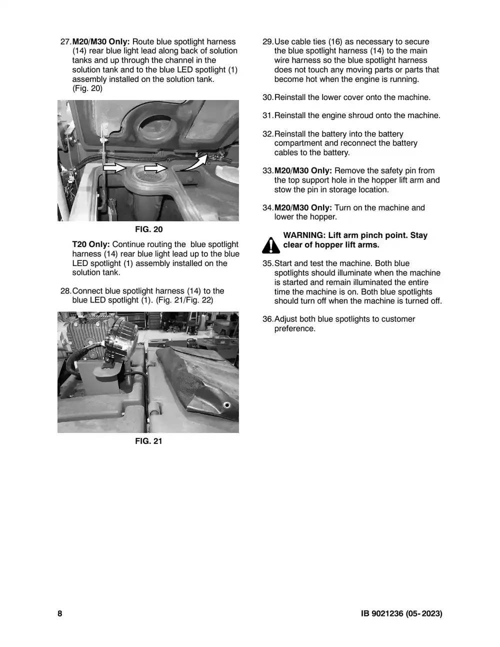
27.M20/M30 Only: Route blue spotlight harness (14) rear blue light lead along back of solution tanks and up through the channel in the solution tank and to the blue LED spotlight (1) assembly installed on the solution tank. (Fig. 20) FIG. 20 T20 Only: Continue routing the blue spotlight harness (14) rear blue light lead up to the blue LED spotlight (1) assembly installed on the solution tank. 28.Connect blue spotlight harness (14) to the blue LED spotlight (1). (Fig. 21/Fig. 22) FIG. 21 8 29.Use cable ties (16) as necessary to secure the blue spotlight harness (14) to the main wire harness so the blue spotlight harness does not touch any moving parts or parts that become hot when the engine is running. 30.Reinstall the lower cover onto the machine. 31.Reinstall the engine shroud onto the machine. 32.Reinstall the battery into the battery compartment and reconnect the battery cables to the battery. 33.M20/M30 Only: Remove the safety pin from the top support hole in the hopper lift arm and stow the pin in storage location. 34.M20/M30 Only: Turn on the machine and lower the hopper. WARNING: Lift arm pinch point. Stay clear of hopper lift arms. 35.Start and test the machine. Both blue spotlights should illuminate when the machine is started and remain illuminated the entire time the machine is on. Both blue spotlights should turn off when the machine is turned off. 36.Adjust both blue spotlights to customer preference. IB 9021236 (05- 2023)
Tennant M20 instruction bulletin 9021236, page 9 of 11
Page 9 of 11
Text of this page
FIG IB 9021236 (05- 2023) Sealed cord grip Nut G. 22 9
Tennant M20 instruction bulletin 9021236, page 10 of 11
Page 10 of 11
Text of this page
1 14 2 3 6 4 5 15 16 FRONT FIG 10 8 14 1 7 2 9 10 11 12 13 6 5 G. 23 IB 9021236 (05- 2023)
Tennant M20 instruction bulletin 9021236, page 11 of 11
Page 11 of 11
Text of this page
Bill Of Materials For Spotlight Kit, Blue, CI [T20/M20/M30] - TN4022024 Tennant Ref. Part No. Description Qty. 1 TN4033715 ) Light, Spot, Blue, LED 2 2 TN4016789 Washer, Lock, Int- Ext, 0.50 2 3 TN4042916 Brkt, Blu Spotlight, Fr, Cover Mtg 1 4 TN4032093 Screw, Pan, M8 X 1.25 X 25, Blk 3 5 TN4016551 Washer, Flat, M8, Fendr 3 6 TN4041929 ) Nut, Hex, Lock, M8 X 1.25, Nl, SS 3 7 TN4042910 Brkt, Blu Spotlight, RR, Frame Mtg 1 8 TN4035367 Screw, Pan, Phl, M5 X 0.80 X 20, SS 4 9 TN4042244 Washer, Flat, 0.25B 0.56D .05, PL, 10 4 10 TN4041991 Nut, Hex, Lock, M5 X 0.80, Nl, SS 4 11 TN4035919 ) Bracket, Sppt, Revl Light 1 12 TN4041992 Screw, Hex, M8 X 1.25 X 20, SS 4 13 TN4035242 Washer, Flat, 0.32B 1.00D .12, SS 4 14 TN4042993 Harness, Blu Spotlight [T20,M20,M30] 1 15 TN4038889 Wire, Tie [w/.25” Fir Tree Clip] 3 16 TN4011908 ) Tie, Cable, 11.3L, 2.75D Max 10 TENNANT COMPANY 10400 Clean Street Eden Prairie, MN 55344- 2650 IB 9021236 (05- 2023) 11

SpeedGleam 5 Burnisher Bill of Materials for Telemetry Kit, 3G- 4G, NA [B5, B7, T7]

Tennant instruction bulletin 9021976 rev. 00Published 02-2023Kit 9021969, 9021970, 9021971, 9021972, 9021973, 9021974, 9021975

What it’s for: Upgrade a 3G telemetry module to a 4G telemetry module on B5, SpeedGleam 5, B7, SpeedGleam 7, T7, Speed Scrub Rider, T500e/SpeedScrub 500, T12, T16, T17, M17, M20, T20, M30, S20E, S20, and S30.

  • Machines: M17, M20, M30, S20, S30, T12, T16, T17, T20
  • M20: all
  • Power: gasoline, LPG and diesel
  • Applies to: telemetry

Time: 60 minutes · Special tools: NONE

Safety warnings (from the bulletin, word for word)

  • FOR SAFETY: Before leaving or servicing machine, stop on level surface, turn off machine, set parking brake (if equipped), and remove key.
  • WARNING: Always disconnect battery cables from machine before working on electrical components.

Tennant says an authorized service provider should install this kit. SES is one: Have SES install this kit.

Parts

Parts for Tennant instruction bulletin 9021976
ItemPart numberQtyDescriptionPrice
TN4187455Old # 90219691SpeedGleam 5 Burnisher Bill of Materials for Telemetry Kit, 3G- 4G, NA [B5, B7, T7]KitCall for availability 800-440-6723
TN4187456Old # 90219701SpeedScrub 500 Scrubber Bill of Materials for Telemetry Kit, 3G- 4G, NA [T500E]KitCall for availability 800-440-6723
TN4187457Old # 90219711Telemetry Kit, 3G- 4G, NA [T12]KitCall for availability 800-440-6723
TN4187458Old # 90219721Telemetry Kit, 3G- 4G, NA [T16]KitCall for availability 800-440-6723
TN4187459Old # 90219731M20 Sweeper Scrubber/M30 Sweeper Scrubber Bill of Materials for Telemetry Kit, 3G- 4G, NA [T20/M20/M30]KitCall for availability 800-440-6723
TN4187460Old # 90219741M17 Sweeper Scrubber Bill of Materials for Telemetry Kit, 3G- 4G, NA [T17/M17]KitCall for availability 800-440-6723
TN4187461Old # 90219751Telemetry Kit, 3G- 4G, NA [S20/S30]KitCall for availability 800-440-6723
1TN4031062Old # 12475071Control Box Assy, Telem [USA, 4G]Call for availability 800-440-6723
2TN4031064Old # 12475222Antenna, Telem [4G, 72”]Call for availability 800-440-6723
1TN4031062Old # 12475071Control Box Assy, Telem [USA, 4G]Call for availability 800-440-6723
2TN4031064Old # 12475222Antenna, Telem [4G, 72”]Call for availability 800-440-6723
1TN4031062Old # 12475071Control Box Assy, Telem [USA, 4G]Call for availability 800-440-6723
2TN4031064Old # 12475222Antenna, Telem [4G, 72”]Call for availability 800-440-6723
1TN4031062Old # 12475071Control Box Assy, Telem [USA, 4G]Call for availability 800-440-6723
2TN4031066Old # 12475692Antenna, Telem [4G, 36]Call for availability 800-440-6723
3TN4038889Old # 12108072Wire, Tie [w/.25” Fir Tree Clip]$1.90/EA
1TN4031062Old # 12475071Control Box Assy, Telem [USA, 4G]Call for availability 800-440-6723
2TN4031064Old # 12475222Antenna, Telem [4G, 72”]Call for availability 800-440-6723
3TN4030314Old # 10704021Angle, Mtg, Antenna, Telem$18.69/EA
4TN4044164Old # 1409162Clamp, Cable, Nyl, 0.62d, Nat$3.40/EA
5TN4035369Old # 241992Screw, Hex, M5 X 0.80 X 16, SS$3.00/EA
6TN4042888Old # 016834Washer, Flat, 10, SS$2.60/EA
7TN4041004Old # 065492Nut, Hex, M5 X 0.80 X 16, 8.8$2.50/EA
8TN4036259Old # 10203411Screw, Hex, M8 X 1.25 X 20, SS, SEMS$3.50/EA
9TN4042902Old # 016852Washer, Flat, 0.38B 0.88D .08, SS$2.60/EA
10TN4041929Old # 087131Nut, Hex, Lock, M8 X 1.25, NL, SS$3.30/EA
1TN4031062Old # 12475071Control Box Assy, Telem [USA, 4G]Call for availability 800-440-6723
2TN4031064Old # 12475222Antenna, Telem [4G, 72”]Call for availability 800-440-6723
3TN4030314Old # 10704021Angle, Mtg, Antenna, Telem$18.69/EA
4TN4044164Old # 1409162Clamp, Cable, Nyl, 0.62d, Nat$3.40/EA
5TN4041258Old # 069272Screw, Pan, Phl, M4 X 0.70 X 16, 4.8$3.30/EA
6TN4042888Old # 016834Washer, Flat, 10, SS$2.60/EA
7TN4041991Old # 097392Nut, Hex, Lock, M5 X 0.80, NL, SS$3.30/EA
8TN4041271Old # 069431Screw, Hex, M6 X 1.00 X 20, 8.8$2.50/EA
9TN4034133Old # 324832Washer, Flat, 0.25, SAE$2.50/EA
10TN4041925Old # 087081Nut, Hex, Lock, M6 X 1.00, NL$2.50/EA
1TN4031062Old # 12475071Control Box Assy, Telem [USA, 4G]Call for availability 800-440-6723
2TN4217709Old # 12483502Antenna, Telem [4G, 180”]$50.89/EA
3TN4011908Old # 7631142Tie, Cable, 11.3L, 2.75D Max$3.30/EA
4TN4028714Old # 552482Mount, Cable Tie$3.70/EA
1TN4031062Old # 12475071Control Box Assy, Telem [USA, 4G]Call for availability 800-440-6723
2TN4217709Old # 12483502Antenna, Telem [4G, 180”]$50.89/EA
3TN4038889Old # 12108074Wire, Tie [w/.25” Fir Tree Clip]$1.90/EA
1TN4031062Old # 12475071Control Box Assy, Telem [USA, 4G]Call for availability 800-440-6723
2TN4217657Old # 12475682Antenna, Telem [4G, 108”]Call for availability 800-440-6723
3TN4011908Old # 7631144Tie, Cable, 11.3L, 2.75D Max$3.30/EA
4TN4028714Old # 552484Mount, Cable Tie$3.70/EA
5TN4044164Old # 1409164Clamp, Cable, Nyl, 0.62d, Nat$3.40/EA
6TN4027333Old # 3823204Screw, Pan, Phl, 12- 16 X 0.50, F/ Plstc$2.50/EA

Bulletin PDF: Sign in to view or downloadSign in to download

Installation instructions (12 pages)
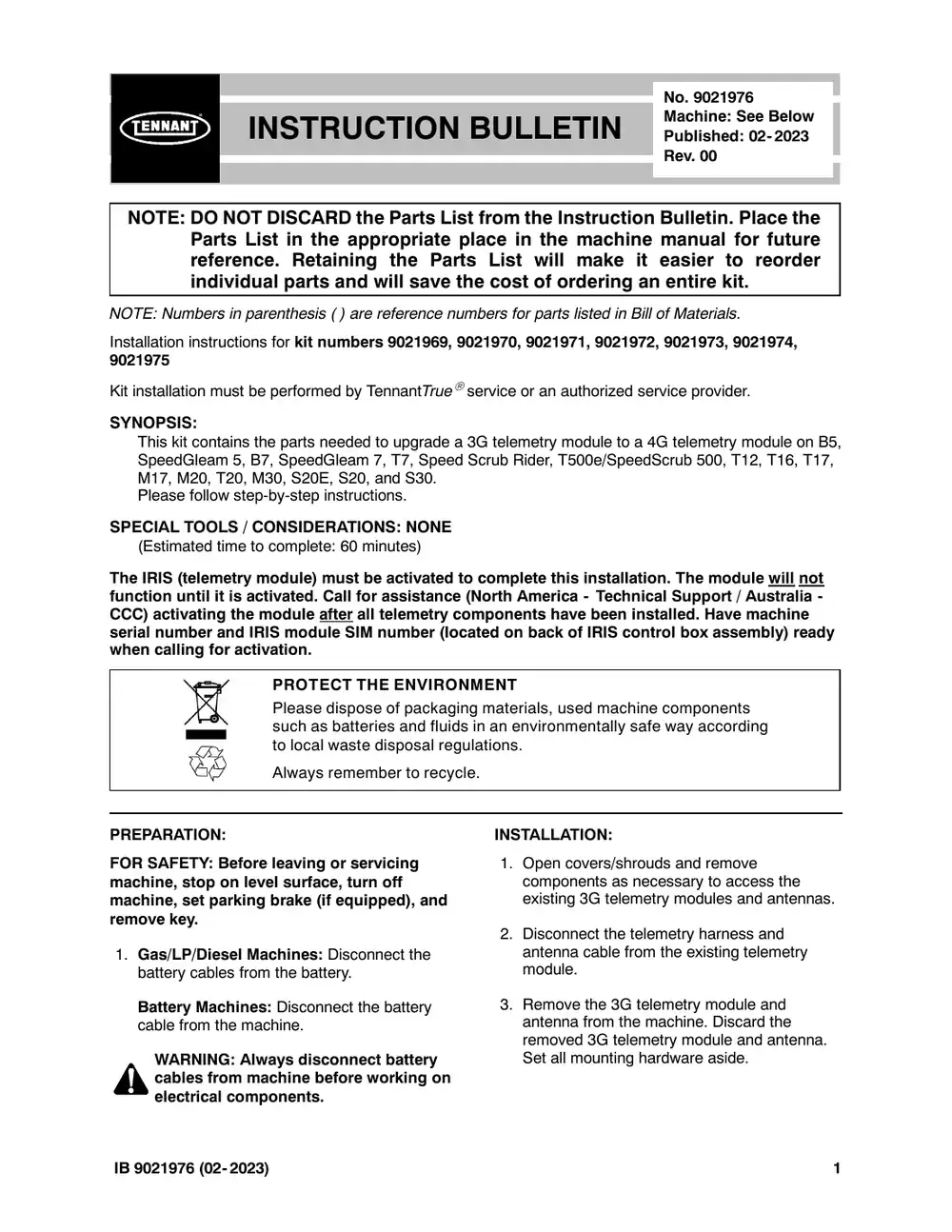
Tennant M20 instruction bulletin 9021976, page 1 of 12
Page 1 of 12 SES ref PF-D4RB-H5W3‌‌​⁠‍‍‌​‌​‍‌⁠‌⁠​⁠‌‌⁠⁠‍​‌⁠‌‌‌​​​‌​‍‌​‌‍​​​‌​‍‌​‍‌⁠​⁠⁠‌⁠​⁠⁠‌‌‍
Text of this page
INSTRUCTION B NOTE: DO NOT DISCARD the Parts List Parts List in the appropriate pla reference. Retaining the Parts individual parts and will save the NOTE: Numbers in parenthesis ( ) are reference num Installation instructions for kit numbers TN4187455, 902 TN4187461 Kit installation must be performed by TennantTruese SYNOPSIS: This kit contains the parts needed to upgrade a 3G SpeedGleam 5, B7, SpeedGleam 7, T7, Speed S M17, M20, T20, M30, S20E, S20, and S30. Please follow step-by-step instructions. SPECIAL TOOLS / CONSIDERATIONS: NONE (Estimated time to complete: 60 minutes) The IRIS (telemetry module) must be activated to function until it is activated. Call for assistance (N CCC) activating the module after all telemetry com serial number and IRIS module SIM number (loca when calling for activation. PROTECT THE ENVIRONM Please dispose of packaging such as batteries and fluids i to local waste disposal regula Always remember to recycle. PREPARATION: FOR SAFETY: Before leaving or servicing machine, stop on level surface, turn off machine, set parking brake (if equipped), and remove key. 1. Gas/LP/Diesel Machines: Disconnect the battery cables from the battery. Battery Machines: Disconnect the battery cable from the machine. WARNING: Always disconnect battery cables from machine before working on electrical components. IB 9021976 (02- 2023) No. 9021976 Machine: See Below BULLETIN Published: 02- 2023 Rev. 00 from the Instruction Bulletin. Place the ace in the machine manual for future s List will make it easier to reorder e cost of ordering an entire kit. mbers for parts listed in Bill of Materials. 21970, TN4187457, TN4187458, TN4187459, TN4187460, ervice or an authorized service provider. 3G telemetry module to a 4G telemetry module on B5, Scrub Rider, T500e/SpeedScrub 500, T12, T16, T17, complete this installation. The module will not North America - Technical Support / Australia - mponents have been installed. Have machine ated on back of IRIS control box assembly) ready MENT g materials, used machine components in an environmentally safe way according ations. . INSTALLATION: 1. Open covers/shrouds and remove components as necessary to access the existing 3G telemetry modules and antennas. 2. Disconnect the telemetry harness and antenna cable from the existing telemetry module. 3. Remove the 3G telemetry module and antenna from the machine. Discard the removed 3G telemetry module and antenna. Set all mounting hardware aside. 1
Tennant M20 instruction bulletin 9021976, page 2 of 12
Page 2 of 12
Text of this page
4. Remove the additional SIM label from the back of the control box (1) and set label aside in a safe place. The number on the SIM label will be needed for activating the machine. (Fig. 2) FIG. 1 5. Use saved hardware to install the new 4G telemetry module (1) onto the machine. 6. Install both 4G telemetry antennas (2) onto the machine. Refer to following figures for both 4G antenna locations on the various machines. Fig. 2 - B5 Burnisher/SpeedGleam 5 Burnisher Fig. 3 - B7 Burnisher/SpeedGleam 7 Burnisher Fig. 4 - T7 Scrubber/Speed Scrub Rider Scrubber Fig. 5 - T500e Scrubber/SpeedScrub 500 Scrubber Fig. 6 - T12 Scrubber Fig. 7 - T16 Scrubber Fig. 8 - T20 Scrubber/M20 Sweeper Scrubber/M30 Sweeper Scrubber Fig. 9 - T17 Scrubber/M17 Sweeper Scrubber Fig. 10 - S20 Sweeper Fig. 11 - S30 Sweeper 2 7. Connect the telemetry harness to the 4G telemetry module (1). 8. Route both 4G antenna (2) cables (along same path as the removed 3G antenna cable had previously been routed) to the 4G telemetry module (1) and connect cables to the 4G telemetry module. NOTE: The IRIS (telemetry module) must be activated to complete this installation. The module will not function until it is activated. Call for assistance activating the module after all telemetry components have been installed. 9. Reconnect the battery cables to the battery/ reconnect the battery cable to the machine. 10.Gas/LP/Diesel Machines: Turn the key to the ON position, but do not start the machine. Battery Machines: Turn the key to the ON position. 11. North America Customer Locations: Activate the IRIS (telemetry module): Call Technical Support (between hours of 7:00 am and 5:00 pm CST) for assistance to activate the module. The IRIS telemetry system must be activated to complete this install. Have the machine serial number and IRIS module SIM number ready when calling for activation. 12. Australia Customer Locations: Activate the IRIS (telemetry module): Call CCC (between hours of 8:00 am and 5:00 pm AEST) and ask to be routed to the IRIS expert for assistance to activate the module. The IRIS telemetry system must be activated to complete this install. Have the machine serial number and IRIS module SIM number ready when calling for activation. NOTE: The IRIS (telemetry module) must be activated to complete this installation. The module will not function until it is activated. Call for assistance activating the module after all telemetry components have been installed. IB 9021976 (02- 2023)
Tennant M20 instruction bulletin 9021976, page 3 of 12
Page 3 of 12
Text of this page
Use saved hardware (self tap screws (Qty. 4) flat washers (Qty. 4)) to install 4G telemetry module (1) onto front shroud FIG. 2 - B5 Burnisher/Sp Bill of Materials for Telemetry Kit, Tennant Ref. Part No. Description 1 TN4031062 Control Box Assy, Telem 2 TN4031064 Antenna, Telem [4G, 72”] IB 9021976 (02- 2023) 2 2 Front 1 shroud Telemetry harness peedGleam 5 Burnisher 3G- 4G, NA [B5, B7, T7] - TN4187455 Qty. [USA, 4G] 1 ] 2 3
Tennant M20 instruction bulletin 9021976, page 4 of 12
Page 4 of 12
Text of this page
Use saved hardware (self tap screws (Qty. 4) flat washers (Qty. 4)) to install 4G telemetry module (1) onto front shroud FIG. 3 - B7 Burnisher/Sp Bill of Materials for Telemetry Kit, Tennant Ref. Part No. Description 1 TN4031062 Control Box Assy, Telem 2 TN4031064 Antenna, Telem [4G, 72”] 4 Front shroud 2 2 1 Telemetry harness peedGleam 7 Burnisher 3G- 4G, NA [B5, B7, T7] - TN4187455 Qty. [USA, 4G] 1 ] 2 IB 9021976 (02- 2023)
Tennant M20 instruction bulletin 9021976, page 5 of 12
Page 5 of 12
Text of this page
Module bracket Telemetry harness FIG. 4 - T7 Scrubber/Spe Bill of Materials for Telemetry Kit, Tennant Ref. Part No. Description 1 TN4031062 Control Box Assy, Telem 2 TN4031064 Antenna, Telem [4G, 72”] IB 9021976 (02- 2023) Use saved hardware (hex nuts (Qty. 4) flat washers (Qty. 4)) to install 4G telemetry module (1) onto module bracket 1 Antenna mounting bracket 2 eed Scrub Rider Scrubber 3G- 4G, NA [B5, B7, T7] - TN4187455 Qty. [USA, 4G] 1 ] 2 5
Tennant M20 instruction bulletin 9021976, page 6 of 12
Page 6 of 12
Text of this page
Control box bracket 2 3 FIG. 5 - T500e Scrubber/S Bill of Materials for Telemetry Ki Tennant Ref. Part No. Description 1 TN4031062 Control Box Assy, Telem 2 TN4031066 Antenna, Telem [4G, 36] 3 TN4038889 Wire, Tie [w/.25” Fir Tree 6 Use saved hardware (hex nuts (Qty. 4) flat washers (Qty. 4)) to install 4G telemetry module (1) onto module bracket 1 SpeedScrub 500 Scrubber it, 3G- 4G, NA [T500E] - TN4187456 Qty. [USA, 4G] 1 2 e Clip] 2 IB 9021976 (02- 2023)
Tennant M20 instruction bulletin 9021976, page 7 of 12
Page 7 of 12
Text of this page
Use saved screws (Qty (Qty. 4), an antenna (2) 2 Antenna mounting angle Steering channel 4 2 FRONT 8 6 3 7 5 6 4 SecondAntenna for 4G 1. Use two M5 hex screws (5), four flat washers ( M5 hex nuts (7), and two cable clamps (4) to ins antenna (2) onto antenna mounting angle (3) 2. Use SEMS M8 hex screw (8) to install antenn mounting angle (3) onto steering channel FIG. 6 - T12 Bill of Materials for Telemetry K Tennant Ref. Part No. Description 1 TN4031062 Control Box Assy, Telem 2 TN4031064 Antenna, Telem [4G, 72”] 3 TN4030314 Angle, Mtg, Antenna, Tele 4 TN4044164 Clamp, Cable, Nyl, 0.62d 5 TN4035369 Screw, Hex, M5 X 0.80 X 6 TN4042888 Washer, Flat, 10, SS 7 TN4041004 Nut, Hex, M5 X 0.80 X 16 8 TN4036259 Screw, Hex, M8 X 1.25 X 9 TN4042902 Washer, Flat, 0.38B 0.88 10 TN4041929 Nut, Hex, Lock, M8 X 1.2 IB 9021976 (02- 2023) components and hardware (M5 hex y 4), flat washers (Qty. 8), M5 hex nuts nd cable clamps (Qty. 2)) to install 4G ) onto antenna mounting angle Telemetry harness Box mounting bracket 1 2 Use saved hardware (M5 hex screws (Qty 4), flat washers (Qty. 8), and M5 hex nuts (Qty.4)) to install 4G telemetry module (1) (6), two onto box mounting bracket stall 4G na 2 Scrubber Kit, 3G- 4G, NA [T12] - TN4187457 Qty. [USA, 4G] 1 ] 2 em 1 d, Nat 2 X 16, SS 2 4 6, 8.8 2 X 20, SS, SEMS 1 8D .08, SS 2 25, NL, SS 1 7
Tennant M20 instruction bulletin 9021976, page 8 of 12
Page 8 of 12
Text of this page
Use saved components Use saved components and hardware (M5 hex screws (Qty 4), flat washers (Qty. 8), M5 hex nuts (Qty. 4), and cable clamps (Qty. 2)) to install 4G antenna (2) onto 2 antenna mounting angle 9 8 6 7 4 9 3 FRONT 5 10 2 4 Steering channel 1. Use two M4 pan screws (5), four flat washers (6), two M5 hex nuts (7), and two cable clamps (4) to install 4G antenna (2) onto antenna mounting angle (3) 2. Use one M6 hex screw (8), two flat washers (9), and one M6 hex nut to install antenna mounting angle (3) onto steering channel FIG. 7 - T16 Bill of Materials for Telemetry K Tennant Ref. Part No. Description 1 TN4031062 Control Box Assy, Telem 2 TN4031064 Antenna, Telem [4G, 72”] 3 TN4030314 Angle, Mtg, Antenna, Tele 4 TN4044164 Clamp, Cable, Nyl, 0.62d 5 TN4041258 Screw, Pan, Phl, M4 X 0. 6 TN4042888 Washer, Flat, 10, SS 7 TN4041991 Nut, Hex, Lock, M5 X 0.8 8 TN4041271 Screw, Hex, M6 X 1.00 X 9 TN4034133 Washer, Flat, 0.25, SAE 10 TN4041925 Nut, Hex, Lock, M6 X 1.0 8 Use saved hardware (M5 Antenna hex screws (Qty 4), flat mounting washers (Qty. 8), and M5 angle hex nuts (Qty.4)) to install 4G telemetry module (1) onto box mounting bracket Telemetry bracket 1 Telemetry harness 6 Scrubber Kit, 3G- 4G, NA [T16] - TN4187458 Qty. [USA, 4G] 1 ] 2 em 1 d, Nat 2 .70 X 16, 4.8 2 4 80, NL, SS 2 X 20, 8.8 1 2 00, NL 1 IB 9021976 (02- 2023)
Tennant M20 instruction bulletin 9021976, page 9 of 12
Page 9 of 12
Text of this page
U (Q tele Accesspanel Use saved components and hardware (M5 hex screws (Qty 4), flat washers (Qty. 2), M5 hex nuts (Qty. 4), and cable clamps (Qty. 2)) to install 4G antenna (2) onto antenna mounting angle 2 Antenna mounting angle Fuse block cover 3 FRONT 4 Use two cable tie mounts (3) and two cable ties ( to install 4G antenna (2) onto fuse block cover FIG. 8 - T20 Scrubber/M20 Sweepe Bill of Materials for Telemetry Kit, 3G Tennant Ref. Part No. Description 1 TN4031062 Control Box Assy, Telem 2 TN4217709 Antenna, Telem [4G, 180 3 TN4011908 Tie, Cable, 11.3L, 2.75D 4 TN4028714 Mount, Cable Tie IB 9021976 (02- 2023) Use saved hardware (hex screws Qty. 4), flat washers (Qty. 4), and hex nuts (Qty. 4)) to install 4G emetry module onto access panel 1 Telemetry harness 4 2 (4) er Scrubber/M30 Sweeper Scrubber G- 4G, NA [T20/M20/M30] - TN4187459 Qty. [USA, 4G] 1 0”] 2 Max 2 2 9
Tennant M20 instruction bulletin 9021976, page 10 of 12
Page 10 of 12
Text of this page
3 2 3 Use two fir tree wire tie clips (3) to install each 4G antenna (2) onto recovery tank FRONT Use saved hardware (hex screws (Qty. 4), flat washers (Qty. 4), and hex nuts (Qty. 4)) to install 4G telemetry module (1) onto telemetry mounting bracket FIG. 9 - T17 Scrubber/M Bill of Materials for Telemetry Kit, Tennant Ref. Part No. Description 1 TN4031062 Control Box Assy, Telem 2 TN4217709 Antenna, Telem [4G, 180 3 TN4038889 Wire, Tie [w/.25” Fir Tree 10 Recovery tank Telemetry mounting bracket 1 Telemetry harness M17 Sweeper Scrubber , 3G- 4G, NA [T17/M17] - TN4187460 Qty. [USA, 4G] 1 0”] 2 e Clip] 4 IB 9021976 (02- 2023)
Tennant M20 instruction bulletin 9021976, page 11 of 12
Page 11 of 12
Text of this page
1. Use two pan screws (6) and two cable clamps (5) to install each 4G telemetry antenna (2) onto hopper cover 2. Use two cable tie mounts (4) and two cable ties (3) to secure 4G telemetry antenna (2) cables to the hopper cover 5 6 2 5 2 5 1 5 6 Hopper cover FRONT Use saved h washers (Qty 4G telemetr FIG. 10 - S2 Bill of Materials for Telemetry Kit Tennant Ref. Part No. Description 1 TN4031062 Control Box Assy, Telem 2 TN4217657 Antenna, Telem [4G, 108 3 TN4011908 Tie, Cable, 11.3L, 2.75D 4 TN4028714 Mount, Cable Tie 5 TN4044164 Clamp, Cable, Nyl, 0.62d 6 TN4027333 Screw, Pan, Phl, 12- 16 X IB 9021976 (02- 2023) Operator station 1 Telemetry harness hardware (M6 hex nuts (Qty. 4), flat y. 4), and sleeves (Qty. 4)) to install ry module (1) onto operator station 20 Sweeper t, 3G- 4G, NA [S20/S30] - TN4187461 Qty. [USA, 4G] 1 8”] 2 Max 4 4 d, Nat 4 X 0.50, F/ Plstc 4 11
Tennant M20 instruction bulletin 9021976, page 12 of 12
Page 12 of 12
Text of this page
Use two pan screws (6) and two cable clamps (5) to install each 4G telemetry antenna (2) hopper cover 2 5 5 6 Hopper cover FIG. 11 - S3 Bill of Materials for Telemetry Kit Tennant Ref. Part No. Description 1 TN4031062 Control Box Assy, Telem 2 TN4217657 Antenna, Telem [4G, 108 3 TN4011908 Tie, Cable, 11.3L, 2.75D 4 TN4028714 Mount, Cable Tie 5 TN4044164 Clamp, Cable, Nyl, 0.62d 6 TN4027333 Screw, Pan, Phl, 12- 16 X TENNANT 10400 Cle Eden Prairie, M 12 Use saved hardware (M5 pan screws (Qty. 4) and flat washers (Qty. 4) to install 4G telemetry module (1) onto fan bracket Telemetry harness 1 Fan bracket FRONT 30 Sweeper t, 3G- 4G, NA [S20/S30] - TN4187461 Qty. [USA, 4G] 1 8”] 2 Max 4 4 d, Nat 4 X 0.50, F/ Plstc 4 COMPANY ean Street MN 55344- 2650 IB 9021976 (02- 2023)

Flasher Kit, Replmt, CI [M/T20]

Tennant instruction bulletin 9020694 rev. 00Published 02-2022Kit 9020695

What it’s for: Replace a flasher on M20 sweeper scrubbers and T20 scrubbers.

  • Machines: M20, T20
  • M20: all
  • Power: gasoline, LPG and diesel
  • Applies to: lights

Time: 15 minutes · Special tools: NONE

Safety warnings (from the bulletin, word for word)

  • FOR SAFETY: Before leaving or servicing machine, stop on level surface, turn off machine, set parking brake, and remove key.
  • WARNING: Always disconnect battery cables from machine before working on electrical components.

Tennant says an authorized service provider should install this kit. SES is one: Have SES install this kit.

Parts

Parts for Tennant instruction bulletin 9020694
ItemPart numberQtyDescriptionPrice
TN4191538Old # 90206951Flasher Kit, Replmt, CI [M/T20]KitCall for availability 800-440-6723
1TN4033517Old # 319221Flasher, HD, 12VDC 25A [#10- 57300]Call for availability 800-440-6723

Bulletin PDF: Sign in to view or downloadSign in to download

Installation instructions (2 pages)
Tennant M20 instruction bulletin 9020694, page 1 of 2
Page 1 of 2 SES ref PF-ISPX-U67L‌‌​⁠‍‍‌​‌​‍‌⁠‌⁠​⁠‌‌⁠‍​⁠‌​‍⁠⁠​​​‌​‍‌​‍‌​⁠​⁠‌‍⁠​‌‍⁠‌​‌‍​​‍​‌‌​
Text of this page
INSTRUCTION B NOTE: DO NOT DISCARD the Parts List Parts List in the appropriate pla reference. Retaining the Parts individual parts and will save the NOTE: Numbers in parenthesis ( ) are reference num Installation instructions for kit number TN4191538 Kit installation must be performed by TennantTruese SYNOPSIS: This kit contains the parts needed to replace a fla Please follow step-by-step instructions. SPECIAL TOOLS / CONSIDERATIONS: NONE (Estimated time to complete: 15 minutes) PROTECT THE ENVIRONM Please dispose of packaging such as batteries and fluids i to local waste disposal regula Always remember to recycle. PREPARATION: FOR SAFETY: Before leaving or servicing machine, stop on level surface, turn off machine, set parking brake, and remove key. 1. Open the front shroud to access the battery and the turn signal components located inside the battery compartment. (Fig. 1) 2. Disconnect the battery cables from the battery. WARNING: Always disconnect battery cables from machine before working on electrical components. IB 9020694 (02- 2022) No. 9020694 Machine: M20/T20 BULLETIN Published: 02- 2022 Rev. 00 from the Instruction Bulletin. Place the ace in the machine manual for future s List will make it easier to reorder e cost of ordering an entire kit. mbers for parts listed in Bill of Materials. ervice or an authorized service provider. asher on M20 sweeper scrubbers and T20 scrubbers. MENT g materials, used machine components in an environmentally safe way according ations. . INSTALLATION: 1. Remove the existing flasher from the finger grip clip/front turn signal harness. Discard the removed flasher. (Fig. 1) 2. Connect the new flasher (1) to the front turn signal harness and insert the flasher into the finger grip clip. (Fig. 1) 3. Reconnect the battery cables to the battery. 4. Turn on the machine. 5. Test the turn signals. Adjust the turn signal switch to left and right turn positions. Ensure both the right and left turn signal lights function when the turn signal switch is adjusted to the respective left or right turn positions. (Fig. 1) 6. Turn off the machine. 7. Close the front shroud. 1
Tennant M20 instruction bulletin 9020694, page 2 of 2
Page 2 of 2
Text of this page
Turn signal switch/turnsignal FRONT mounting bracket Right instrument panel Finger grip clip 1 Front shroud Operator compartment Front turn signal harness FIG. 1 Bill Of Materials For Flasher Kit, Replmt, CI [M/T20] - TN4191538 Tennant Ref. Part No. Description Qty. 1 TN4033517 ) Flasher, HD, 12VDC 25A [#10- 57300] 1 TENNANT COMPANY P. O. Box 1452 Minneapolis, MN 55440-1452 2 IB 9020694 (02- 2022)

leaks. Turn off spacer (7). (Fig. 3) the machine and recheck the antifreeze level. Add antifreeze as necessary. Bill of Materials for Repair Kit, Sheave

Tennant instruction bulletin 9021788 rev. 00Published 01-2022Kit 9021787

What it’s for: Replace the sheave assembly on M20/M30/T20 machines equipped with Mitsubishi 2.0L Gas or LP engines.

  • Machines: M20, M30, T20
  • M20: all
  • Power: Gasoline, LPG
  • Engine: Mitsubishi
  • Applies to: Mitsubishi engine

Time: 3 hours · Special tools: NONE

Safety warnings (from the bulletin, word for word)

  • FOR SAFETY: Before leaving or servicing machine, stop on level surface, turn off machine, and remove key.

Tennant says an authorized service provider should install this kit. SES is one: Have SES install this kit.

Parts

Parts for Tennant instruction bulletin 9021788
ItemPart numberQtyDescriptionPrice
TN4018217Old # 90217871leaks. Turn off spacer (7). (Fig. 3) the machine and recheck the antifreeze level. Add antifreeze as necessary. Bill of Materials for Repair Kit, SheaveKit$373.80/EA
1TN4032383Old # 12579861Sheave, Mach$109.40/EA
2TN4214590Old # 12577061Plate Wldt, Shaft, Fan$154.70/EA
3TN4038766Old # 10553772Bearing, Ball, 20mmb 42mmd 12mmw$12.60/EA
4TN4016811Old # 413583Screw, Soc, M10 X 1.50 X 35, 12.9$4.00/EA
5TN4035242Old # 10172182Washer, Flat, 0.32b 1.00d .12, SS$3.40/EA
6TN4041284Old # 069593Screw, Hex, M8 X 1.25 X 100, 8.8$4.00/EA
7TN4030317Old # 10704311Spacer, Fan, Taper [Mit 2013]$107.60/EA
8TN4042788Old # 009601Key, Sq, 0.12 X 0.12, 0.50l$3.60/EA
9TN4178853Old # 10748492Ring, Retaining, Int, 42mm$1.20/EA
10TN4156940Old # 392771Screw, Hex, M8 X 1.25 X 25, 8.8$3.20/EA
11TN4034137Old # 324911Washer, Flat, 0.31, Std$2.50/EA
12TN4033875Old # 10251212Ring, Retaining, Shaft, Ext, 20mmd, HD$19.30/EA
13TN4203177Old # 167991Adhesive, Anaerobic, 0.5ml [609]Call for availability 800-440-6723

Bulletin PDF: Sign in to view or downloadSign in to download

Installation instructions (5 pages)
Tennant M20 instruction bulletin 9021788, page 1 of 5
Page 1 of 5 SES ref PF-ZGAU-UJRX‌‌​⁠‍‍‌​‌​‍‌⁠‌⁠​⁠‌‌⁠⁠⁠⁠‌​‌‌⁠​​​‌​‍‌​‌​​​‌​‌‌‍⁠‍⁠⁠‍‍⁠​⁠‍‍​⁠‌‍
Text of this page
INSTRUCTION NOTE: DO NOT DISCARD the Parts List Parts List in the appropriate pla reference. Retaining the Parts individual parts and will save the NOTE: Numbers in parenthesis ( ) are reference num Installation instructions for kit number TN4018217 Kit installation must be performed by TennantTruese SYNOPSIS: This kit contains the parts needed to replace the s equipped with Mitsubishi 2.0L Gas or LP engines. Please follow step-by-step instructions. SPECIAL TOOLS / CONSIDERATIONS: NONE (Estimated time to complete: 3 hours) PROTECT THE ENVIRONM Please dispose of packaging such as batteries and fluids i to local waste disposal regula Always remember to recycle. PREPARATION: 1. Park the machine on a clean level surface, turn off the machine, remove the key, and set the parking brake. FOR SAFETY: Before leaving or servicing machine, stop on level surface, turn off machine, and remove key. 2. Open and/or remove shrouds/covers necessary to access the engine. INSTALLATION: 1. Loosen the hardware securing the fan shroud weldment to the machine. Set the removed hardware aside. (Fig. 1) 2. Remove the hardware securing the fan skirt to the fan shroud weldment. Set the hardware aside. (Fig. 1) IB 9021788 (01- 2022) No. 9021788 Machine: M20/M30/T20 N BULLETIN Published: 01- 2022 Rev. 00 from the Instruction Bulletin. Place the ace in the machine manual for future s List will make it easier to reorder e cost of ordering an entire kit. mbers for parts listed in Bill of Materials. ervice or an authorized service provider. sheave assembly on M20/M30/T20 machines . MENT g materials, used machine components in an environmentally safe way according ations. . 3. Drain the antifreeze from the coolant system. Dispose the drained antifreeze. 4. Remove the radiator/radiator mounting bracket from the machine. Set the radiator/radiator mounting bracket and all mounting hardware aside. (Fig. 1) NOTE: Do Not disassemble the radiator mounting bracket from the radiator. 5. Remove the fan shroud weldment from the machine. Set the fan shroud weldment and all mounting hardware aside. (Fig. 1) 6. Remove the fan upper support bracket from the machine. Set the hardware securing fan upper support bracket to the fan shroud aside. Discard the fan upper support bracket and the hardware that secured the fan upper support bracket to the engine. (Fig. 1) 1
Tennant M20 instruction bulletin 9021788, page 2 of 5
Page 2 of 5
Text of this page
Discard both fan upper support bracket/hardware securing fan Radiator upper support bracket to engine mounting bracket Fan shroud weldment Fanshroud Remove Do Not remove hardware radiator mounting securing fan skirt bracket from to fan shroud radiator FIG 7. Remove the fan shroud from the machine. Set the fan shroud and mounting hardware aside. (Fig. 1) 8. Remove the cooling fan from the engine. Set cooling fan and all hardware aside. (Fig. 2) 9. Remove the engine belt from the machine. Set the fan belt aside. (Fig. 2) 2 Lower fan shroud support Remove hardware bracket securing radiator/ radiator mounting bracket to machine FRONT Fan skirt G. 1 10.Remove the sheave and fan hub pulley from the machine. Discard the sheave, spacer, key, bearings, and all mounting hardware. (Fig. 2) 11.Remove the hardware securing the alternator arm to the fan shaft plate. Set the hardware aside. (Fig. 2) IB 9021788 (01- 2022)
Tennant M20 instruction bulletin 9021788, page 3 of 5
Page 3 of 5
Text of this page
12.Remove/move components necessary to access and remove the fan shaft plate from the machine. Set all removed items aside. (Fig. 1/Fig. 2) Tensioner assembly Remove and set fan belt aside Remove and discard fan Remove and shaft plate set cooling fan and hardware aside Remove and discard hardware (Qty. 3) FRONT Torsional damper pulley Remove and Lo discard ha hardware Alternator arm FIG IB 9021788 (01- 2022) 13.Remove the fan shaft plate from the machine. Set all mounting hardware aside. Discard the fan shaft plate. (Fig. 2) Remove and discard fan spacer, key, sheave, bearings, and all mounting hardware oosen ardware Fan guard Alternator G. 2 3
Tennant M20 instruction bulletin 9021788, page 4 of 5
Page 4 of 5
Text of this page
Tensioner assembly Cooling fan belt 9 1 9 8 3 12 7 4 2 Cooling fan and hardware 5 6 11 10 Alternator arm FRO Torsional damper pulley FIG 14. Insert both retaining rings (9) into the new sheave (1). (Fig. 3) 15. Press both ball bearings (3) into the sheave (1) and against the retaining rings (9) installed in the previous step. (Fig. 3) 4 12 3 9 ONT G. 3 16. Install one retaining ring (12) into the inner notch in the fan shaft plate (2) shaft. (Fig. 3) IB 9021788 (01- 2022)
Tennant M20 instruction bulletin 9021788, page 5 of 5
Page 5 of 5
Text of this page
17. Apply a light/even coat of anaerobic adhesive (13) onto the shaft of the fan shaft plate (2) and the inner portion of both ball bearings (3) pressed into the sheave (1) in the previous step. (Fig. 3) 18. Slide the sheave (1) onto the fan shaft plate (2). (Fig. 3) 19. Install the remaining retaining ring (12) into the outer notch in the fan shaft plate (2) shaft to completely secure the sheave (1) onto the shaft. (Fig. 3) 20. Use three M8 hex screws (6) and three flat washers (5) to install the fan shaft plate assembly (2) onto the engine. (Fig. 3) 21. Use three socket screws (4) to install the fan spacer (7) onto the sheave assembly (1). (Fig. 3) 22. Use one M8 hex screw (10) and one flat washer (11) to install the alternator arm onto the fan shaft plate (2). (Fig. 3) 23. Tighten loosened hardware to fully secure the alternator arm to the alternator. (Fig. 3) 24. Position the engine belt onto the sheave (1), torsional damper pulley, and the tensioner assembly pulley. (Fig. 3) 25. Insert the key (8) into the notch in the fan spacer (7). (Fig. 3) Bill of Materials for Repa Tennant Ref. Part No. Description 1 TN4032383 Sheave, Mach 2 TN4214590 Plate Wldt, Shaft, Fan 3 TN4038766 Bearing, Ball, 20mmb 42m 4 TN4016811 Screw, Soc, M10 X 1.50 5 TN4035242 ) Washer, Flat, 0.32b 1.00d 6 TN4041284 Screw, Hex, M8 X 1.25 X 7 TN4030317 Spacer, Fan, Taper [Mit 2 8 TN4042788 Key, Sq, 0.12 X 0.12, 0.5 9 TN4178853 Ring, Retaining, Int, 42m 10 TN4156940 ) Screw, Hex, M8 X 1.25 X 11 TN4034137 Washer, Flat, 0.31, Std 12 TN4033875 Ring, Retaining, Shaft, Ex 13 TN4203177 Adhesive, Anaerobic, 0.5 TENNANT 10400 Cle Eden Prairie, M IB 9021788 (01- 2022) 26. Install the cooling fan onto the fan spacer (7). Be sure the key (8) remains in the notch when installing the cooling fan onto the fan spacer. (Fig. 3) 27. Tighten the engine belt to the appropriate tension. Refer to the Maintenance section of Operators manual for the engine belt tension. 28. Reinstall the fan shroud onto the machine. 29. Use saved hardware to install the fan shroud onto the fan shaft plate assembly (2). 30. Reinstall the fan shroud weldment onto the machine. 31. Secure the fan skirt to the fan shroud weldment. 32. Reinstall the radiator onto the machine. 33. Refill the engine cooling system with the appropriate amount of fresh antifreeze. Do Not reuse removed antifreeze. Refer to the Specifications section of the Operators Manual for the required amount. NOTE: Be sure all air is purged from the cooling system and the antifreeze is at the correct level in the reservior before operating the machine. 34. Start and run machine for several minutes. Observe the coolant system for leaks. Turn off the machine and recheck the antifreeze level. Add antifreeze as necessary. air Kit, Sheave - TN4018217 Qty. 1 1 mmd 12mmw 2 X 35, 12.9 3 d .12, SS 2 X 100, 8.8 3 2013] 1 50l 1 mm 2 X 25, 8.8 1 1 xt, 20mmd, HD 2 5ml [609] 1 COMPANY ean Street MN 55344- 2650 5

Sensor Kit Recovery Tank Afmkt Std

Tennant instruction bulletin 9021416 rev. 00Published 06-2021Kit 9021418

What it’s for: Replace the recovery float sensor on M20/M30 sweeper scrubbers and T20 scrubbers without the optional ES system.

  • Machines: M20, M30, T20
  • M20: all
  • Power: gasoline, LPG and diesel
  • Applies to: ES (extended scrub)

Time: 45 minutes · Special tools: 5/8 in. (16

Safety warnings (from the bulletin, word for word)

  • FOR SAFETY: Before leaving or servicing machine, stop on level surface, turn off machine, set parking brake, and remove key.
  • WARNING: Always disconnect battery cables from machine before working on electrical components.

Tennant says an authorized service provider should install this kit. SES is one: Have SES install this kit.

Parts

Parts for Tennant instruction bulletin 9021416
ItemPart numberQtyDescriptionPrice
TN4018130Old # 90214181Sensor Kit Recovery Tank Afmkt StdKitCall for availability 800-440-6723
1TN4021025Old # 3856851Sensor, Level, Liq, 14VDC 01A .62- 11$78.50/EA
2TN4035907Old # 10192851Bracket, Protector, Float SwitchCall for availability 800-440-6723

Bulletin PDF: Sign in to view or downloadSign in to download

Installation instructions (2 pages)
Tennant M20 instruction bulletin 9021416, page 1 of 2
Page 1 of 2 SES ref PF-RYZK-Z4OW‌‌​⁠‍‍‌​‌​‍‌⁠‌⁠​⁠‌‌⁠⁠‌‌‌​​​​​​​‌​‍‌​‍⁠⁠‌​​‍‌⁠‌⁠‍⁠‌​‌‍‍​⁠⁠‌‍‍
Text of this page
INSTRUCTION B NOTE: DO NOT DISCARD the Parts List Parts List in the appropriate pla reference. Retaining the Parts individual parts and will save the NOTE: Numbers in parenthesis ( ) are reference num Installation instructions for kit number TN4018130 Kit installation must be performed by TennantTruese SYNOPSIS: This kit contains the parts needed to replace the r scrubbers and T20 scrubbers without the optional Please follow step-by-step instructions. SPECIAL TOOLS / CONSIDERATIONS: 5/8 in. (16 (Estimated time to complete: 45 minutes) PROTECT THE ENVIRONM Please dispose of packaging such as batteries and fluids i to local waste disposal regula Always remember to recycle. PREPARATION: 1. Completely empty the recovery tank. FOR SAFETY: Before leaving or servicing machine, stop on level surface, turn off machine, set parking brake, and remove key. 2. Disconnect the battery cables from the battery. WARNING: Always disconnect battery cables from machine before working on electrical components. INSTALLATION: 1. Open the recovery tank cover. 2. Disconnect the main harness from the existing recovery tank liquid level sensor. 3. Drill a 5/8 in. (16 mm) hole into the side of the recovery tank where the slight indentation (dimple) is located. (Fig. 1) IB 9021416 (06- 2021) No. 9021416 Machine: M20/M30/T20 BULLETIN Published: 06- 2021 Rev. 00 from the Instruction Bulletin. Place the ace in the machine manual for future s List will make it easier to reorder e cost of ordering an entire kit. mbers for parts listed in Bill of Materials. ervice or an authorized service provider. recovery float sensor on M20/M30 sweeper al ES system. 6 mm) drill bit MENT g materials, used machine components in an environmentally safe way according ations. . 4. Remove the lock nut and gasket from the new liquid level sensor (1). (Fig. 1) 5. Route the main wire harness liquid level sensor to where new liquid sensor (1) will be installed and connect the main harness to the new liquid level sensor. 6. Use the lock nut and gasket to install the liquid level sensor (1) and float switch protector bracket (2) into the recovery tank. (Fig. 1) NOTE: Position the liquid level sensor so the narrow end of the float mechanism is oriented as shown in Fig. 1. 7. Test the machine. Observe the area where the new liquid level sensor (1) was installed for leaks. Ensure there is an alert when the recovery tank is full. The liquid level sensor is functioning correctly when there is a recovery tank full alert when the liquid level in the tank reaches the sensor. 1
Tennant M20 instruction bulletin 9021416, page 2 of 2
Page 2 of 2
Text of this page
Gasket and lock nut included with liquid level sensor (1) 2 Noteliquid level sensor (1) orientation 5/8 in. (16 mm) hole where slight indentation (dimple) is located on recovery tank FRONT Replace old recovery tank liquid level sensor with new liquid level sensor (1) FIG. 1 Bill Of Materials For Sensor Kit Recovery Tank Afmkt Std - TN4018130 Tennant Ref. Part No. Description Qty. 1 TN4021025 ) Sensor, Level, Liq, 14VDC 01A .62- 11 1 2 TN4035907 Bracket, Protector, Float Switch 1 TENNANT COMPANY 10400 Clean Street Eden Prairie, MN 55344- 2650 2 IB 9021416 (06- 2021)

8 in. (16 mm) hole was drilled in the previous step. (Fig. 11) Bill Of Materials For Sensor Kit Recovery Tank Afmkt ES

Tennant instruction bulletin 9021417 rev. 00Published 06-2021Kit 9021419

What it’s for: Replace the liquid level sensors on M20/M30/T20 machines equipped with the optional ES system.

  • Machines: M20, M30, T20
  • M20: all
  • Power: gasoline, LPG and diesel
  • Applies to: ES (extended scrub)

Time: M20- 1 hour, M30- 1.5 hours, T20- 2.5 hours · Special tools: NONE

Safety warnings (from the bulletin, word for word)

  • WARNING: Raised hopper may fall. Engage hopper support pin.
  • WARNING: Lift arm pinch point. Stay clear of hopper lift arms.
  • FOR SAFETY: Before leaving or servicing machine, stop on level surface, turn off machine, set parking brake, and remove key.
  • WARNING: Always disconnect battery cables from machine before working on electrical components.

Tennant says an authorized service provider should install this kit. SES is one: Have SES install this kit.

Parts

Parts for Tennant instruction bulletin 9021417
ItemPart numberQtyDescriptionPrice
TN4018132Old # 902141918 in. (16 mm) hole was drilled in the previous step. (Fig. 11) Bill Of Materials For Sensor Kit Recovery Tank Afmkt ESKitCall for availability 800-440-6723
1TN4021025Old # 3856852Sensor, Level, Liq, 14VDC 01A .62- 11$78.50/EA
2TN4035907Old # 10192852Bracket, Protector, Float SwitchCall for availability 800-440-6723
3TN4231946Old # 10767661Harness, Elec, Rec Tank JumperCall for availability 800-440-6723

Bulletin PDF: Sign in to view or downloadSign in to download

Installation instructions (7 pages)
Tennant M20 instruction bulletin 9021417, page 1 of 7
Page 1 of 7 SES ref PF-N7H6-FHWQ‌‌​⁠‍‍‌​‌​‍‌⁠‌⁠​⁠‌‌⁠⁠‍‌‌‍‌‌‍​​​‌​‍‌​‌⁠‍⁠⁠‌‌⁠‍‌‍⁠‌‍‌‌⁠‍​‌‍‌‍‌
Text of this page
INSTRUCTION B NOTE: DO NOT DISCARD the Parts List Parts List in the appropriate pla reference. Retaining the Parts individual parts and will save the NOTE: Numbers in parenthesis ( ) are reference num Installation instructions for kit number TN4018132 Kit installation must be performed by TennantTruese SYNOPSIS: This kit contains the parts needed to replace the l equipped with the optional ES system. Please follow step-by-step instructions. SPECIAL TOOLS / CONSIDERATIONS: NONE (Estimated time to complete: M20- 1 hour, M30- 1 PROTECT THE ENVIRONM Please dispose of packaging such as batteries and fluids i to local waste disposal regula Always remember to recycle. PREPARATION: ALL MACHINES (Unless otherwise noted) 1. Completely empty the recovery tank. 2. M20/M30 machines only: Turn on the machine, raise the hopper to the middle support position, engage the hopper support pin, and turn off the machine. WARNING: Raised hopper may fall. Engage hopper support pin. WARNING: Lift arm pinch point. Stay clear of hopper lift arms. FOR SAFETY: Before leaving or servicing machine, stop on level surface, turn off machine, set parking brake, and remove key. IB 9021417 (06- 2021) No. 9021417 Machine: M20/M30/T20 BULLETIN (w/ES Only) Published: 06- 2021 Rev. 00 from the Instruction Bulletin. Place the ace in the machine manual for future s List will make it easier to reorder e cost of ordering an entire kit. mbers for parts listed in Bill of Materials. ervice or an authorized service provider. liquid level sensors on M20/M30/T20 machines 1.5 hours, T20- 2.5 hours) MENT g materials, used machine components in an environmentally safe way according ations. . 3. Disconnect the battery cables from the battery. WARNING: Always disconnect battery cables from machine before working on electrical components. 4. Open the recovery tank cover and secure the cover open. 5. Disconnect the main harness from the existing recovery tank liquid level sensor. (Fig. 1) NOTE: If installing kit onto M20/M30 machines proceed to INSTALLATION: M20/M30. If installing kit onto T20 machine proceed to INSTALLATION: T20. 1
Tennant M20 instruction bulletin 9021417, page 2 of 7
Page 2 of 7
Text of this page
Recovery tank FRONT Although a new float sensor switch is replacing existing pressure switch assembly, leave pressure switch assembly, hose, and fitting installed in recovery tank FIG INSTALLATION: M20/M30 1. M20 machines only: Disconnect the wire harness from the existing float sensor. (Fig. 2) FIG. 2 2. M20 machines only: Remove all hardware securing the existing float sensor/protector bracket to the recovery tank and remove the sensor and bracket from the recovery tank. Discard the float sensor, protector bracket, and all hardware. (Fig. 3/ Fig. 4) 2 Disconnect wireharness from existing pressure switch assembly G. 1 FIG. 3 FIG. 4 IB 9021417 (06- 2021)
Tennant M20 instruction bulletin 9021417, page 3 of 7
Page 3 of 7
Text of this page
3. M30 Machines only: Drill a 5/8 in. (16 mm) hole into the side of the recovery tank where the slight indentation (dimple) is located. (Fig. 5) 4. M30 machines only: Route the main wire harness liquid level sensor to where new liquid sensor (1) will be installed and connect the main harness to the new liquid level sensor. M30 (16 sl (dim FRONT FIG IB 9021417 (06- 2021) 5. Remove the lock nut and gasket from one of the new liquid level sensors (1). 6. Use the lock nut and gasket to install the liquid level sensor (1) and float switch protector bracket (2) into the recovery tank. (Fig. 5) NOTE: Position the liquid level sensor so the narrow end of the float mechanism is oriented as shown in Fig. 5. Gasket and lock nut included with liquid level sensor (1) 2 Note liquid level sensor orientation 0 only: Drill 5/8 in. 6 mm) hole where light indentation mple) is located on recovery tank Replace old recoverytankliquid level sensor with new liquid level sensor (1) G. 5 3
Tennant M20 instruction bulletin 9021417, page 4 of 7
Page 4 of 7
Text of this page
7. Drill a 5/8 in. (16 mm) hole into the side of the recovery tank. (Fig. 6) 8. Remove the lock nut and gasket from the remaining new liquid level sensor (1). FIG 4 9. Use the lock nut and gasket to install the liquid level sensor (1) and float switch protector bracket (2) into the 5/8 in. (16 mm) hole drilled into the side of the recovery tank. (Fig. 6) NOTE: Position the liquid level sensor (1) so the narrow end of the float mechanism is oriented as shown. Drill 5/8 in. (16 mm) hole into recovery tank G. 6 IB 9021417 (06- 2021)
Tennant M20 instruction bulletin 9021417, page 5 of 7
Page 5 of 7
Text of this page
10.Connect the jumper harness (3) to the wire harness connection previously attached to the old float sensor. 11.Route the wire harness/ jumper cable (3) to the lower float sensor (1) just installed onto the side of the recovery tank and connect the jumper harness to the float sensor. 12.Test the machine. Observe the area where the new liquid level sensors (1) were installed for leaks. INSTALLATION: T20 1. Open the recovery tank cover. 2. Disconnect the main harness from the existing recovery tank liquid level sensor. 3. Remove the recovery tank drain hose from the storage location on the back of the recovery tank. 4. Remove the float switch shield from the recovery tank. Set the float switch shield and hardware aside. (Fig. 7) FIG. 7 IB 9021417 (06- 2021) 5. Remove all hardware securing the existing float sensor cable to the back of the recovery tank and disconnect the wire harness from the float sensor. Set all hardware aside. (Fig. 8) FIG. 8 6. Remove the float sensor from the recovery tank. Discard the float sensor and protector bracket. (Fig. 9) FIG. 9 7. Remove the lock nut and gasket from both new liquid level sensors (1). 5
Tennant M20 instruction bulletin 9021417, page 6 of 7
Page 6 of 7
Text of this page
Gasket and lock nut se included with liquid level sensor (1) FRONT FIG 8. Use the lock nut and gasket to install a new liquid level sensor (1) and float switch protector bracket (2) into the back of the recovery tank where the removed float sensor was previously located. (Fig. 10). NOTE: Position the liquid level sensor (1) so the narrow end of the float mechanism is oriented as shown in Fig. 10. 9. Connect the wire harness to the liquid level sensor (1) installed in the previous step. (Fig. 10) 6 Note liquid level ensor orientation Replace old recovery tank liquid level sensor with new liquid level 2 sensor (1) G. 10 IB 9021417 (06- 2021)
Tennant M20 instruction bulletin 9021417, page 7 of 7
Page 7 of 7
Text of this page
10.Measure and mark location for the bottom 5/8 in. (16 mm) hole needed for the additional float switch (1) to be installed onto the back of the recovery tank. Center hole in recessed area of recovery tank and 1 in. (25.4 mm) from bottom edge of recessed area. (Fig. 11) FIG. 11 11.Drill a 5/8 in. (16 mm) hole into the back of the recovery tank marked in the previous step. (Fig. 11) 12.Use the lock nut and gasket to install the remaining new liquid level sensor (1) and float switch protector bracket (2) into the back of the recovery tank where the 5/8 in. (16 mm) hole was drilled in the previous step. (Fig. 11) Bill Of Materials For Sensor Kit Re Tennant Ref. Part No. Description 1 TN4021025 ) Sensor, Level, Liq, 14VD 2 TN4035907 Bracket, Protector, Float 3 TN4231946 Harness, Elec, Rec Tank TENNANT 10400 Cle Eden Prairie, M IB 9021417 (06- 2021) 13.Connect the jumper harness (3) to the wire harness connection previously attached to the old float sensor. 14.Cut enough of the portion of conduit covering the cable end previously connected to the old sensor away so there is enough cable for the jumper harness (3) to reach the lower float switch (1) installed into the back of the recovery tank. 15.Route the wire harness/ jumper cable (3) to the lower float sensor (1) installed onto the back of the recovery tank and connect the jumper harness to the float sensor. 16.Wrap electric tape around the previously cut portion of the conduit to secure the remaining wires/cable inside the conduit. 17.Test the machine. Observe the area where the new liquid level sensors (1) were installed for leaks. ecovery Tank Afmkt ES - TN4018132 Qty. DC 01A .62- 11 2 Switch 2 Jumper 1 COMPANY ean Street MN 55344- 2650 7

Motor Kit, Replmt [M20/T20/M30]

Tennant instruction bulletin 9016245 rev. 00Published 07-2019Kit 9016242

What it’s for: Replace scrub vacuum fan motor on M20 (NA serial numbers 006877- ) (CE serial numbers 1000- ) / T20 (NA serial numbers 005892- ) (CE serial numbers 1000- ) / M30 (serial numbers 004455- ) machines.

  • Machines: M20, M30, T20
  • M20 SN 006877 and later
  • Power: gasoline, LPG and diesel

Time: 5- 7 hours (5 hours if hydraulic system is vacuumed down, 7 hours if hydraulic fluid is removed · Special tools: (Estimated time to complete: 5- 7 hours (5 hours i hydraulic fluid is removed)) 1. Thoroughly clean outside of hydraulic component and flush hoses and fittings with air, solvent, or hy ports to prevent contaminants from entering syste 2. Mark hydraulic hoses with locations of where they hoses to proper locations. 3. Discard all hydraulic fluid drained from the system hydraulic reservoir. Hydraulic fluid is potentially da and local laws/regulations governing the disposal disposing hydraulic fluid. PROTECT THE ENVIRONM Please dispose of packaging such as batteries and fluids i to local waste disposal regula Always remember to recycle.

Safety warnings (from the bulletin, word for word)

  • FOR SAFETY: Before leaving or servicing machine, stop on level surface, turn off machine, and remove key.
  • WARNING: Always disconnect battery cables from machine before working on electrical components. NOTE: Do not discard removed parts unless instructed to do so. Most parts are reinstalled after the scrub vacuum fan is replaced.

Parts

Parts for Tennant instruction bulletin 9016245
ItemPart numberQtyDescriptionPrice
TN4024031Old # 90162421Motor Kit, Replmt [M20/T20/M30]Kit$794.80/EA
1TN4030528Old # 10712531Motor, Hyd, Gear, Ext 0.17 LH 3000Call for availability 800-440-6723
2TN4041602Old # 077881Nut, Hex, Std, M12 x 1.75, SS$3.40/EA
3TN4041943Old # 090104Screw, Hex, M8 X 1.25 X 25, SS$3.30/EA
4TN4042902Old # 016854Washer, Flat, 0.38B 0.88D .08, SS$2.60/EA
5TN4041929Old # 087134Nut, Hex. Lock, M8 X 1.25, NL, SS$3.30/EA
6TN4011921Old # 763151Fitting, Hyd, Tee, JF08/JM08/JM08, Br$15.10/EA
7TN4013874Old # 475131Fitting, Hyd, E45, JM08/OM10$34.20/EA
8TN4025261Old # 770981Fitting, Hyd, E90, JM06/OM04$15.50/EA
9TN4029146Old # 566921Fitting, Hyd, Str, JM08/OM10$10.60/EA
10TN4030456Old # 363281Washer, Flat, Belleville, .50$4.10/EA

Bulletin PDF: Sign in to view or downloadSign in to download

Installation instructions (8 pages)
Tennant M20 instruction bulletin 9016245, page 1 of 8
Page 1 of 8 SES ref PF-Z7ZH-CUDL‌‌​⁠‍‍‌​‌​‍‌⁠‌⁠​⁠‌‌⁠‌​⁠‍​‍‌​​​​‌​‍‌​‌​‌​​‌‍‌‍⁠⁠​‌‍‌‍‌‍​‍​‌⁠⁠
Text of this page
INSTRUCTION NOTE: DO NOT DISCARD the Parts List Parts List in the appropriate pla reference. Retaining the Parts individual parts and will save the NOTE: Numbers in parenthesis ( ) are reference num Installation instructions for kit number TN4024031 SYNOPSIS: This kit contains the parts needed to replace scru 006877- ) (CE serial numbers 1000- ) / (CE serial numbers 1000- ) / M30 (serial num Please follow step-by-step instructions. SPECIAL TOOLS / CONSIDERATIONS: (Estimated time to complete: 5- 7 hours (5 hours i hydraulic fluid is removed)) 1. Thoroughly clean outside of hydraulic component and flush hoses and fittings with air, solvent, or hy ports to prevent contaminants from entering syste 2. Mark hydraulic hoses with locations of where they hoses to proper locations. 3. Discard all hydraulic fluid drained from the system hydraulic reservoir. Hydraulic fluid is potentially da and local laws/regulations governing the disposal disposing hydraulic fluid. PROTECT THE ENVIRONM Please dispose of packaging such as batteries and fluids i to local waste disposal regula Always remember to recycle. PREPARATION: 1. Park the machine on a clean level surface , turn off the machine, engage the parking brake, and remove the key. FOR SAFETY: Before leaving or servicing machine, stop on level surface, turn off machine, and remove key. IB 9016245 (07- 2019) No. 9016245 Machine: M20 / M30 / N BULLETIN T20 Published: 07- 2019 Rev. 00 from the Instruction Bulletin. Place the ace in the machine manual for future s List will make it easier to reorder e cost of ordering an entire kit. mbers for parts listed in Bill of Materials. ub vacuum fan motor on M20 (NA serial numbers T20 (NA serial numbers 005892- ) mbers 004455- ) machines. if hydraulic system is vacuumed down, 7 hours if ts before disconnecting hydraulic hoses or fittings ydraulic fluid and cap disconnected hoses or open em. y are attached. Markings make it easier to reconnect m. Use only new approved hydraulic fluid to replenish angerous to the environment. Obey all federal, state, of environmentally hazardous materials when MENT g materials, used machine components in an environmentally safe way according ations. . 2. Disconnect the battery cables from the battery. WARNING: Always disconnect battery cables from machine before working on electrical components. NOTE: Do not discard removed parts unless instructed to do so. Most parts are reinstalled after the scrub vacuum fan is replaced. 3. Remove the engine cover from the machine. Set the engine cover aside. 1
Tennant M20 instruction bulletin 9016245, page 2 of 8
Page 2 of 8
Text of this page
4. Remove the coolant reservoir from the bracket and move the reservoir away from the scrub vacuum fan. (Fig. 1) NOTE: If necessary, unplug spark plug cables before moving the coolant reservoir. FIG. 1 5. Remove the hardware holding the air cleaner bracket to the machine and move the air cleaner/air cleaner bracket away from the scrub vacuum fan. (Fig. 2) FIG. 2 6. Drain hydraulic fluid from the system. NOTE: It is not necessary to drain hydraulic fluid if a hydraulic vacuum is used to vacuum down the hydraulic system. 2 INSTALLATION: 1. Disconnect the hose attached to location P1 on the scrub valve. (Fig. 3) FIG. 3 2. Disconnect all main wire harness connections from the scrub valve. 3. Remove the support bracket. Set the support bracket and hardware aside. (Fig. 4) FIG. 4 IB 9016245 (07- 2019)
Tennant M20 instruction bulletin 9016245, page 3 of 8
Page 3 of 8
Text of this page
4. Loosen the hardware holding the scrub valve bracket to the solution tank. (Fig. 5) FIG. 5 5. Lift the scrub valve assembly up from the hardware and away from the solution tank. (Fig. 6) FIG. 6 IB 9016245 (07- 2019) 6. Disconnect the four hydraulic hoses from the fittings on the scrub fan motor. Leave fittings installed on the scrub fan motor. (Fig. 7) Scrub fan hydraulic motor FIG. 7 NOTE: If working on an LP machine, the fuel tank can be removed to make access to scrub vacuum fan easier. Refer to Operators Manual for instructions how to remove LP tank. NOTE: If working on a diesel or gasoline machine without FaST, ES, or spray hose options, the operator station removable panel can be removed to make access to scrub fan easier. Set the panel and hardware aside. (Fig. 8) FIG. 8 3
Tennant M20 instruction bulletin 9016245, page 4 of 8
Page 4 of 8
Text of this page
Note: Do Not remove components other than those notes in the instructions from the scrubbing vacuum fan assembly to install kit onto machine. Assembly shown disassembled to show part locations. 6 9 8 1 4 7 5 FIG 7. Remove the scrubbing vacuum fan assembly from the solution tank. Set the cable clamp and all hardware aside. (Fig. 9) 4 2 10 3 Solution tank G. 9 8. Remove the scrub fan motor from the scrubbing vacuum fan assembly. Set the vacuum fan assembly and all hardware aside. Discard the scrub fan motor and all fittings installed on the motor. (Fig. 9) IB 9016245 (07- 2019)
Tennant M20 instruction bulletin 9016245, page 5 of 8
Page 5 of 8
Text of this page
9. Remove the crown nut holding the impeller onto the hydraulic motor. Discard the crown nut. (Fig. 10) FIG. 10 10. Pry the impeller from the scrubber vacuum fan. Set the impeller aside. (Fig. 9 / Fig. 11) FIG. 11 11. Remove the plugs from the new hydraulic motor (1). 12. Install the straight fitting (9) into the hydraulic motor (1). (Fig. 12) IB 9016245 (07- 2019) 13. Install the t- fitting (6) into the straight fitting (9) installed into hydraulic motor (1) in the previous step. Do not completely tighten t- fitting. The t- fitting is tightened during later adjustment. Note location of Allen screw on the scrubbing fan hydraulic motor. (Fig. 12) 6 Note Allen screw location 9 on hydraulic motor 1 8 7 FIG. 12 14. Install the 90_ fitting (8) onto the scrubbing fan hydraulic motor (1). (Fig. 12) 15. Install the 45_ fitting (7) onto the scrubbing fan hydraulic motor (1). (Fig. 12) 16. Use four M8 hex screws (3), four washers (4), and four M8 hex nuts (5) to install the hydraulic motor (1) onto the scrubber vacuum fan housing. (Fig. 9) 17. Apply a light coat of anti- seize lubricant onto the shaft of the hydraulic motor (1). 18. Place the impeller onto the hydraulic motor (1) shaft. (Fig. 9) 19. Apply a light coat of Loctite® 242t onto the threads of the M12 hex nut (2). 20. Use the M12 hex nut (2) and Belleville washer (10) to secure the impeller onto the hydraulic motor (1). (Fig. 9) Loctite® and 242tare registered trademarks of the Henkel 5
Tennant M20 instruction bulletin 9016245, page 6 of 8
Page 6 of 8
Text of this page
Corporation. 1 Vac Fa Motor (Scrub 8 Vac Fan Reservoir Motor (Sweep) (M20 / M30 Only) Propel Pump FIG 21. Reinstall the scrub vacuum fan onto the solution tank. (Fig. 9) 22. Connect the hydraulic hoses previously disconnected from the removed scrubbing vacuum fan assembly to the new scrubbing vacuum fan assembly. (Fig. 13) 23. Reinstall the scrub valve assembly onto the solution tank. (Fig. 14) FIG. 14 6 6 Scrub and Sweep Valve P1 9 an b) M4 1 8 7 Aux Pump G. 13 24. Reconnect the hose removed from location P1 on the scrub valve. (Fig. 15) FIG. 15 25. Reconnect the main wire harness to the scrub valve. IB 9016245 (07- 2019)
Tennant M20 instruction bulletin 9016245, page 7 of 8
Page 7 of 8
Text of this page
26. Reinstall the support bracket. (Fig. 16) FIG. 16 27. Reinstall the air cleaner assembly/air cleaner assembly bracket onto the machine. (Fig. 17) FIG. 17 IB 9016245 (07- 2019) 28. Reinstall the coolant reservoir onto the bracket. (Fig. 18) FIG. 18 29. If hydraulic fluid was drained to install this kit, replenish the hydraulic system with Tennant approved hydraulic fluid. Refer to the Operators Manual for additional information. 30. Reinstall the LP tank, operator station removable panel, and other parts/ components removed to install the new vacuum fan motor kit onto the machine. 31. Reconnect the battery cables to the battery. 32. Start and test the machine. Observe the scrub vacuum fan motor/fittings and other hydraulic components that had been removed for leaks. Operate the scrub vacuum fan to ensure it functions. 7
Tennant M20 instruction bulletin 9016245, page 8 of 8
Page 8 of 8
Text of this page
Bill of Materials for Motor Kit, Replmt [M20/T20/M30] - TN4024031 Tennant Ref. Part No. Description Qty. 1 TN4030528 Motor, Hyd, Gear, Ext 0.17 LH 3000 1 2 TN4041602 Nut, Hex, Std, M12 x 1.75, SS 1 3 TN4041943 Screw, Hex, M8 X 1.25 X 25, SS 4 4 TN4042902 Washer, Flat, 0.38B 0.88D .08, SS 4 5 TN4041929 Nut, Hex. Lock, M8 X 1.25, NL, SS 4 6 TN4011921 Fitting, Hyd, Tee, JF08/JM08/JM08, Br 1 7 TN4013874 Fitting, Hyd, E45, JM08/OM10 1 8 TN4025261 Fitting, Hyd, E90, JM06/OM04 1 9 TN4029146 Fitting, Hyd, Str, JM08/OM10 1 10 TN4030456 Washer, Flat, Belleville, .50 1 TENNANT COMPANY P. O. Box 1452 Minneapolis, MN 55440-1452 8 IB 9016245 (07- 2019)

Panel Kit, Pod, Afmkt [M17, Touch Screen]

Tennant instruction bulletin 9015637 rev. 01Published 03-2020Kit 9015042, 9015633

What it’s for: Replace Pro- Panel assembly on M17/M20/M30/T20 machines.

  • Machines: M17, M20, M30, T20
  • M20: all
  • Power: gasoline, LPG and diesel
  • Applies to: Pro-Panel

Time: 45- 60 minutes · Special tools: NONE

Safety warnings (from the bulletin, word for word)

  • FOR SAFETY: Before leaving or servicing machine, stop on level surface, turn off machine, set parking brake, and remove key.
  • WARNING: Always disconnect battery cables from machine before working on electrical components.

Parts

Parts for Tennant instruction bulletin 9015637
ItemPart numberQtyDescriptionPrice
TN4022937Old # 90150421Panel Kit, Pod, Afmkt [M17, Touch Screen]KitCall for availability 800-440-6723
TN4023703Old # 90156331Panel Kit, Pod, Afmkt [Pro, M20/M30/T20]Kit$2,226.60/EA
1TN1215588Old # 12155881Panel Assy [M17, UI, Touch Screen]Call for availability 800-440-6723
1TN4224038Old # 12250471Panel Assy [UI, Touchscreen]Call for availability 800-440-6723

Bulletin PDF: Sign in to view or downloadSign in to download

Installation instructions (12 pages)
Tennant M20 instruction bulletin 9015637, page 1 of 12
Page 1 of 12 SES ref PF-AAU6-TY2Q‌‌​⁠‍‍‌​‌​‍‌⁠‌⁠​⁠‌‌⁠‍⁠⁠‍⁠⁠⁠‌​​​‌​‍‌​‌‌​⁠‍⁠⁠⁠​‍‍​​⁠‌​‌​‍‍‌‍‌​
Text of this page
INSTRUCTION B NOTE: DO NOT DISCARD the Parts List Parts List in the appropriate pla reference. Retaining the Parts individual parts and will save the NOTE: Numbers in parenthesis ( ) are reference num Installation instructions for kit number TN4023703/9015 SYNOPSIS: This kit contains the parts needed to replace Pro- Please follow step-by-step instructions. SPECIAL TOOLS / CONSIDERATIONS: NONE (Estimated time to complete: 45- 60 minutes) PROTECT THE ENVIRONM Please dispose of packaging such as batteries and fluids i to local waste disposal regula Always remember to recycle. PREPARATION (M20/M30/T20 ONLY): 1. If the pod assembly on machine is operable, connect service computer to the pod, turn the key to the ON position, but do not start the machine, start the Capture application, and note machine settings. The new pod assembly (1) will need to be configured to the same settings. FOR SAFETY: Before leaving or servicing machine, stop on level surface, turn off machine, set parking brake, and remove key. 2. Disconnect the battery cables from the battery. WARNING: Always disconnect battery cables from machine before working on electrical components. 3. Open the front shroud to access the steering mechanism components. IB 9015637 (03- 2020) No. 9015637 Machine: M20/T20/ BULLETIN M30/M17 Published: 03- 2020 Rev. 01 from the Instruction Bulletin. Place the ace in the machine manual for future s List will make it easier to reorder e cost of ordering an entire kit. mbers for parts listed in Bill of Materials. 5042 - Panel assembly on M17/M20/M30/T20 machines. MENT g materials, used machine components in an environmentally safe way according ations. . INSTALLATION (M20/M30/T20 ONLY): 1. Disconnect the pod cables from the main wire harness. (Fig. 1) FIG. 1 1
Tennant M20 instruction bulletin 9015637, page 2 of 12
Page 2 of 12
Text of this page
2. Loosen the socket screws (Qty. 2) securing the pod assembly into the steering tilt bracket. (Fig. 2/Fig. 3) FIG. 2 3. Pull the pod assembly out from the steering assembly. (Fig. 3) 1 Thrust washers (Qty. 2) FRONT FIG 2 4. Remove the two thrust washers from the pod assembly. Set the thrust washers aside. Discard the removed pod assembly. (Fig. 3) 5. Slide the thrust washers onto the new pod assembly (1). (Fig. 3) 6. Insert the new pod assembly (1) into the steering assembly. (Fig. 3) 7. Orient the pod assembly (1) so the display is positioned correctly in the steering wheel and tighten the two socket screws to secure the pod assembly into the steering tilt bracket. (Fig. 2/Fig. 3) 8. Connect the pod assembly (1) to the main wire harness. 9. Reconnect the battery cables to the battery. Steering wheel Steering tilt bracket G. 3 IB 9015637 (03- 2020)
Tennant M20 instruction bulletin 9015637, page 3 of 12
Page 3 of 12
Text of this page
PREPARATION (M17 ONLY): 1. If pod assembly on machine is operable, connect service computer to the pod, turn the key to the ON position, start the Capture application, and note machine settings. The new Pro- Panel pod assembly (1) must be configured to the same settings. NOTE: If Pro- Panel pod assembly is completely inoperable, the machine configuration settings will need to be set to the optional equipment on the machine and / or set to the standard default settings. 2. If pod assembly on machine is operable, record the hours from the hour meter. FOR SAFETY: Before leaving or servicing machine, stop on level surface, turn off machine, set parking brake, and remove key. 3. Disconnect the battery cable from the machine. WARNING: Always disconnect battery cables from machine before working on electrical components. 4. Remove the electrical access panel from the machine. Set the electrical access panel and all hardware aside. (Fig. 4) FIG. 4 IB 9015637 (03- 2020) INSTALLATION (M17 ONLY): 1. Disconnect the main wire harness and rear view camera cable from the Pro- Panel pod assembly. (Fig. 6) 2. Loosen the M6 set screws securing the Pro- Panel pod assembly in the bearing plate. (Fig. 5/Fig. 6) FIG. 5 3. Pull the Pro- Panel pod assembly from the steering mechanism. (Fig. 6) 4. Remove both thrust washers from the Pro- Panel pod assembly. Set the thrust washers aside. Discard the Pro- Panel pod assembly. (Fig. 6) 5. Slide the thrust washers onto the new Pro- Panel pod assembly (1). (Fig. 6) 6. Carefully insert the Pro- Panel pod assembly (1) into the steering mechanism. Do Not damage cables when inserting the Pro- Panel pod into the steering mechanism. (Fig. 6) 7. Position the Pro- Panel pod assembly (1) so it is properly aligned on the steering wheel. (Fig. 6) 8. Tighten the two M6 set screws to secure the Pro- Panel pod assembly (1) inside the bearing plate. (Fig. 5/Fig. 6) 9. Connect the main wire harness and the rear view camera cable to the Pro- Panel pod assembly (1). (Fig. 6) 10. Reinstall the electrical access panel onto the machine. 11. Reconnect the battery cable to the machine. 3
Tennant M20 instruction bulletin 9015637, page 4 of 12
Page 4 of 12
Text of this page
FRONT 1 Thrust washers (Qty. 2) Inductor (CE / Australia Only): Install onto new Pro- Panel pod assembly (1) To: Main wire harness To: Rear view camera Loosen M6 *Bearing set screws plate (Qty. 2) *Do Not remove bearing plate from machine/steering mechanism when replacing Pro- Panel pod assembly (1). Parts shown disassembled to better show part locations FIG. 6 4 IB 9015637 (03- 2020)
Tennant M20 instruction bulletin 9015637, page 5 of 12
Page 5 of 12
Text of this page
TENNANT SERVICE APPLICATION SOFTWARE (ALL MACHINES): Download the service application software as described below. For Tennant service personnel equipped with ServiceLink computers, the software is already installed on the service computer. The software application is titled “Service Diagnostics”. (Fig. 7) Icon on Desktop From Start menu From Start menu > All Programs > Tennant Company > Tennant Service Diagnostics FIG. 7 IB 9015637 (03- 2020) For other Service Groups, the Service Application Software can be downloaded from the Tennant Public website as described below. NOTE: If the Service Application Software is currently installed on the service computer, confirm or reinstall the software to ensure latest software version is installed. To access the Service Application Software, go to www.tennantco.com. Depending on geographic location, the website may have a “Log in/Sign Up” button at the upper right or a “My Tennant Customer Sign In” tab at the upper right of the Tennant website. (Fig. 8) Proceed with the software download instructions as described on the following pages. Website with “Log In / Sign Up” button (Access to “My Account”) OR Website with “My Tennant Customer Sign In” tab (Access to My Tennant) FIG. 8 5
Tennant M20 instruction bulletin 9015637, page 6 of 12
Page 6 of 12
Text of this page
Website with “Log In / Sign Up” button: (Access to “My Account”) (ALL MACHINES): 1. Log in or Sign Up to create an account. (Fig. 9) FIG. 9 2. Once logged in to the “My Account” website, click on the “INTERNAL RESOURCES” link. (Fig. 10) FIG. 10 3. Click on the “SERVICE APPLICATION SOFTWARE” link. (Fig. 11) FIG. 11 6 4. Within the Service Application Software page, click on the link titled “Service Diagnostics LE version 1.5.12” or later. (Fig. 9) FIG. 12 5. To download the service software continue to click as instructed then click the Save button. (Fig. 13) FIG. 13 6. Open the “Downloads” folder and locate the “LE_Setup_xxxx” zip file. Open the zip file and double click on the “LE_Setup_xxx” file to install the application software on service computer. Follow instructions on screen to install. (Fig. 14) FIG. 14 7. Proceed to PROGRAM THE CONTROL BOARD. IB 9015637 (03- 2020)
Tennant M20 instruction bulletin 9015637, page 7 of 12
Page 7 of 12
Text of this page
PROGRAM THE CONTROL BOARD (ALL MACHINES): If any problems are encountered during the programming process, contact the Technical Service Department for support. 1. Access the software through either the desktop icon or the Start Menu. The software application is titled “Service Diagnostics”. (Fig. 15/Fig. 16/Fig. 17) FIG. 15 From Start menu FIG. 16 Start menu > All Programs > Tennant Company > Tennant Service Diagnostics FIG. 17 IB 9015637 (03- 2020) 2. Start the Service Software Application program. The following screen will appear. (Fig. 18) FIG. 18 3. Connect the USB cable to the computer and the USB port on machine. Turn the key switch to the ON position. 4. The application software will connect to the machine. (Fig. 19) FIG. 19 If the application remains on the “Connecting to Machine...” screen for an extended period, cycle key or close and restart the application software. If it still fails to connect, restart the computer. 7
Tennant M20 instruction bulletin 9015637, page 8 of 12
Page 8 of 12
Text of this page
5. The following screen appears when the application software is connected to machine (Fig. 20). Enter the machine serial number from the label on machine (ex. M17- 12345678). Select the appropriate model from the drop- down menu. Press the arrow button to advance to next screen. FIG. 20 6. Carefully select the correct installed options on the machine (Fig. 21). This may require visually inspecting the machine to confirm all installed options. Press the arrow button to advance to next screen. NOTE: If the machine is configured with an option it does not have, a fault code may appear during machine start up. FIG. 21 8 7. The application will begin configuring the new control board. Allow the configuration process to be completed. (Fig. 22) FIG. 22 8. The Machine Setup Complete screen appears after configuration is complete. (Fig. 23) FIG. 23 9. Disconnect the USB cable from the machine and turn key off. The machine is now ready for operation. 10. Test machine to ensure all installed options are functioning and no fault codes appear. If a fault code appears, proceed to next step. 11. Reconnect the USB cable to the computer and the machine. The Main Menu will appear on the computer screen. IB 9015637 (03- 2020)
Tennant M20 instruction bulletin 9015637, page 9 of 12
Page 9 of 12
Text of this page
12. Check the machine configuration selections for incorrect installed options. Select the Configuration button. (Fig. 24) FIG. 24 13. Correct the installed options. (Fig. 25) FIG. 25 14. Press the down arrow button to program the machine. A green check appears next to the down arrow button when programmed. (Fig. 25) IB 9015637 (03- 2020) 15. Cycle key to apply the corrected configuration setting. NOTE: The hour meter on Gas / LPG does not need to be reset. The newly installed pod will automatically reset to the correct hour meter reading based on the hour setting (engine run time) from the engine. 16. Disconnect the USB cable from the machine. 9
Tennant M20 instruction bulletin 9015637, page 10 of 12
Page 10 of 12
Text of this page
RESET THE HOUR METER (ALL MACHINES): NOTE: Screens included in this section of the IB are screen from the M17. The same screens exist for the M20/M30/T20 machines but may be different in appearance or have slightly different nomenclature. 1. Use the keypad to enter the supervisor mode log in number into the display above the keypad. Press the enter button when finished entering the log in number. (Fig. 26) NOTE: If necessary, call Field Service Support for the service log in number. FIG. 26 2. The supervisor mode screen should appear in the display. Press the settings button to access the settings screen. (Fig. 27) FIG. 27 10 3. Select the Service Modes button to access the service modes. If necessary use up and down arrow buttons to scroll to the Service Modes button. (Fig. 28) FIG. 28 4. Use the left arrow button and right arrow button to scroll to the Configuration Mode. Press the Check Mark button to access the configuration mode. (Fig. 29) FIG. 29 5. Use the left arrow button and right arrow button to scroll to the C16: Propel H.M.. Press the Check Mark button to access the C16: Propel H.M. log in. (Fig. 30) FIG. 30 IB 9015637 (03- 2020)
Tennant M20 instruction bulletin 9015637, page 11 of 12
Page 11 of 12
Text of this page
6. Log in to the C16: Propel H.M. Screen (hour meter reset password is 0000): Use the minus (- ) button to enter 0 (zero) at first asterisk. Use right arrow button to move to next asterisk and again use the minus (- ) button to enter 0 (zero). Repeat for the remaining asterisks. Press the Check Mark button when finished. (Fig. 31) FIG. 31 7. Press the Check Mark button when finished entering 0 (zero) at the last asterisk. (Fig. 31) 8. Reset the hour meter at the C17: Chg Prpl Hr screen: Use the minus (- ) button and plus (+) button to set/reset numbers and the right arrow button to move to the next number. If necessary, use left arrow button to move back to previous number. (Fig. 32) FIG. 32 NOTE: If hour meter can not be viewed due to pod being inoperable call Field Service Support for the hour meter time from last time the machine was serviced. 9. Press the Check Mark button when finished entering the time for the hour meter. (Fig. 32) 10. Turn key switch to OFF position to turn off the machine/exit the Config Mode. IB 9015637 (03- 2020) RESET THE HOPPER ROLL OUT (M17 ONLY): 1. Turn the key to the ON position and ensure hopper is completely lowered and rolled in. The hopper must be completely lowered and rolled in (in the home position) before it can be reset to the factory roll settings. 2. Use the keypad to enter the supervisor mode log in number into the display above the keypad. Press the enter button when finished entering the log in number. The Service Mode screen should appear in the display. (Fig. 33/ Fig. 34) NOTE: If necessary, call Field Service Support for the service log in number. FIG. 33 3. Press the settings button. The Service Mode setting screen should appear in the display. (Fig. 34/Fig. 35) FIG. 34 11
Tennant M20 instruction bulletin 9015637, page 12 of 12
Page 12 of 12
Text of this page
4. Use the down arrow button to scroll down to the Service Modes button and select the Service Modes button to access the service modes. (Fig. 35) FIG. 35 5. Use the left arrow button and right arrow button to scroll to the Manual Mode. Press the Check Mark button to access the manual mode. (Fig. 36) FIG. 36 Bill Of Materials For Panel Kit, Pod, A Tennant Ref. Part No. Description 1 TN1215588 ) Panel Assy [M17, UI, Tou Bill Of Materials For Panel Kit, Pod, Tennant Ref. Part No. Description 1 TN4224038 ) Panel Assy [UI, Touchscr TENNANT P. O. Bo Minneapolis, M 12 6. Use the left arrow button to scroll to M:35 Fact SetRoll. Press the Check Mark button once to enter M:35 and again to reset the hopper roll out to the factory setting. (Fig. 37) FIG. 37 7. Verify the value on the left closely matches the value in the parentheses. (Fig. 37) NOTE: The hopper factory roll out setting may fluctuate +/- 0.002 when reset. This is normal. 8. Turn key switch to OFF position to turn off the machine/exit the Manual Mode. 9. Retest machine to ensure all installed options are functioning. Activate the rear view camera to ensure it functions. Operate the machine with the various scrub/sweep functions to ensure all the controls/buttons function. Raise, roll out, lower, and roll in the hopper to ensure all hopper functions are operational. Afmkt [M17, Touch Screen] - TN4022937 Qty. uch Screen] 1 Afmkt [Pro, M20/M30/T20] - TN4023703 Qty. reen] 1 COMPANY ox 1452 MN 55440-1452 IB 9015637 (03- 2020)

Fan Kit, Scb, Replmt [M20/T20/M30]

Tennant instruction bulletin 9016244 rev. 00Published 01-2018Kit 9016241

What it’s for: Replace scrub vacuum fan motor on M20 sweeper scrubbers (serial numbers 006878- ), M30 sweeper scrubbers (serial numbers 006878- ), and T20 scrubbers (serial numbers 005893- ).

  • Machines: M20, M30, T20
  • M20 SN 006878 and later
  • Power: gasoline, LPG and diesel

Time: 5- 7 hours (5 hours if hydraulic system is vacuumed down, 7 hours if hydraulic fluid is removed · Special tools: (Estimated time to complete: 5- 7 hours (5 hours i hydraulic fluid is removed)) 1. Thoroughly clean outside of hydraulic component and flush hoses and fittings with air, solvent, or hy ports to prevent contaminants from entering syste 2. Mark hydraulic hoses with locations of where they hoses to proper locations. 3. Discard all hydraulic fluid drained from the system hydraulic reservoir. Hydraulic fluid is potentially da and local laws/regulations governing the disposal disposing hydraulic fluid. PROTECT THE ENVIRONM Please dispose of packaging such as batteries and fluids i to local waste disposal regula Always remember to recycle.

Safety warnings (from the bulletin, word for word)

  • FOR SAFETY: Before leaving or servicing machine, stop on level surface, turn off machine, and remove key.
  • WARNING: Always disconnect battery cables from machine before working on electrical components.

Parts

Parts for Tennant instruction bulletin 9016244
ItemPart numberQtyDescriptionPrice
TN4193415Old # 90162411Fan Kit, Scb, Replmt [M20/T20/M30]Kit$1,594.40/EA
1TN4030069Old # 10686111Plate Wldt, Mtg, Fan$197.90/EA
2TN4034909Old # 10620331Impeller, 11.81d X 0.500b$473.30/EA
3TN4015364Old # 542743Isolator, Vib, Bshg, 1.1d 0.6l .4b 0.78h$14.70/EA
4TN4030528Old # 10712531Motor, Hyd, Gear, Ext 0.17 Lh 3000Call for availability 800-440-6723
5TN4041602Old # 077881Nut, Hex, Std, M12 X 1.75, SS$3.40/EA
6TN4041943Old # 090104Screw, Hex, M8 X 1.25 X 25, SS$3.30/EA
7TN4042902Old # 016857Washer, Flat, 0.38b 0.88d .08, SS$2.60/EA
8TN4041929Old # 087134Nut, Hex, Lock, M8 X 1.25, Nl, SS$3.30/EA
9TN4011921Old # 763151Fitting, Hyd, Tee, Jf08/Jm08/Jm08, Br$15.10/EA
10TN4013874Old # 475131Fitting, Hyd, E45, Jm08/Om10$34.20/EA
11TN4025261Old # 770981Fitting, Hyd, E90, Jm06/Om04$15.50/EA
12TN4029146Old # 566921Fitting, Hyd, Str, Jm08/Om10$10.60/EA
13TN4184443Old # 10686443Angle, Sppt, Fan$11.30/EA
14TN4032056Old # 10316171Seal, Afmkt, Bulb, Str, .75d F/07ga 08ft$102.70/EA
15TN4156940Old # 392773Screw, Hex, M8 X 1.25 X 25, 8.8$3.20/EA
16TN4035242Old # 10172186Washer, Flat, 0.32b 1.00d .12, Ss$3.40/EA
17TN4041992Old # 097403Screw, Hex, M8 X 1.25 X 20, Ss$3.30/EA
18TN4036801Old # 10591001Housing, Fan, Radial Discharge, Sq Inlet$19.40/EA
19TN4030456Old # 363281Washer, Flat, Belleville, .50$4.10/EA
20TN4041944Old # 090112Screw, Hex, M8 X 1.25 X 30, SS$3.40/EA
21TN4041945Old # 090231Screw, Hex, M8 X 1.25 X 35, Fl, SS$3.30/EA

Bulletin PDF: Sign in to view or downloadSign in to download

Installation instructions (8 pages)
Tennant M20 instruction bulletin 9016244, page 1 of 8
Page 1 of 8 SES ref PF-AKGR-NDXF‌‌​⁠‍‍‌​‌​‍‌⁠‌⁠​⁠‌‌⁠‌⁠⁠‍‍⁠​‍​​​‌​‍‌​​‌‌​​⁠​⁠⁠⁠‍​​⁠⁠⁠‌‍​‍​⁠​‍
Text of this page
INSTRUCTION NOTE: DO NOT DISCARD the Parts List Parts List in the appropriate pla reference. Retaining the Parts individual parts and will save the NOTE: Numbers in parenthesis ( ) are reference num Installation instructions for kit number TN4193415 SYNOPSIS: This kit contains the parts needed to replace scru (serial numbers 006878- ), M30 sweeper sc scrubbers (serial numbers 005893- ). Please follow step-by-step instructions. SPECIAL TOOLS / CONSIDERATIONS: (Estimated time to complete: 5- 7 hours (5 hours i hydraulic fluid is removed)) 1. Thoroughly clean outside of hydraulic component and flush hoses and fittings with air, solvent, or hy ports to prevent contaminants from entering syste 2. Mark hydraulic hoses with locations of where they hoses to proper locations. 3. Discard all hydraulic fluid drained from the system hydraulic reservoir. Hydraulic fluid is potentially da and local laws/regulations governing the disposal disposing hydraulic fluid. PROTECT THE ENVIRONM Please dispose of packaging such as batteries and fluids i to local waste disposal regula Always remember to recycle. PREPARATION: 1. Park the machine on a clean level surface, turn off the machine, engage the parking brake, and remove the key. FOR SAFETY: Before leaving or servicing machine, stop on level surface, turn off machine, and remove key. IB 9016244 (01- 2018) No. 9016244 Machine: M20 / M30 / N BULLETIN T20 Published: 01- 2018 Rev. 00 from the Instruction Bulletin. Place the ace in the machine manual for future s List will make it easier to reorder e cost of ordering an entire kit. mbers for parts listed in Bill of Materials. ub vacuum fan motor on M20 sweeper scrubbers crubbers (serial numbers 006878- ), and T20 if hydraulic system is vacuumed down, 7 hours if ts before disconnecting hydraulic hoses or fittings ydraulic fluid and cap disconnected hoses or open em. y are attached. Markings make it easier to reconnect m. Use only new approved hydraulic fluid to replenish angerous to the environment. Obey all federal, state, of environmentally hazardous materials when MENT g materials, used machine components in an environmentally safe way according ations. . 2. Disconnect the battery cables from the battery. WARNING: Always disconnect battery cables from machine before working on electrical components. 3. Remove the engine cover from the machine. Set the engine cover aside. 1
Tennant M20 instruction bulletin 9016244, page 2 of 8
Page 2 of 8
Text of this page
4. Remove the coolant reservoir from the bracket and move the reservoir away from the scrub vacuum fan. (Fig. 1) NOTE: If necessary, unplug spark plug wires before moving the coolant reservoir. FIG. 1 5. Remove the hardware holding the air cleaner bracket to the machine and move the air cleaner / air cleaner bracket away from the scrub vacuum fan. (Fig. 2) FIG. 2 6. Drain hydraulic fluid from the system. NOTE: It is not necessary to drain hydraulic fluid if a hydraulic vacuum is used to vacuum down the hydraulic system. 2 INSTALLATION: 1. Disconnect the hose attached to location P1 on the scrub valve. (Fig. 3) FIG. 3 2. Disconnect all main wire harness leads from the scrub valve. 3. Remove the support bracket. Set the support bracket and hardware aside. (Fig. 4) FIG. 4 IB 9016244 (01- 2018)
Tennant M20 instruction bulletin 9016244, page 3 of 8
Page 3 of 8
Text of this page
4. Loosen the hardware holding the scrub valve bracket to the solution tank. (Fig. 5) FIG. 5 5. Lift the scrub valve assembly up from the hardware and away from the solution tank. (Fig. 6) FIG. 6 IB 9016244 (01- 2018) 6. Disconnect the four hydraulic hoses from the fittings on the scrub fan hydraulic motor. Leave fitting installed on the scrub fan motor. (Fig. 7) Scrub fan hydraulic motor FIG. 7 NOTE: If working on an LP machine, the fuel tank can be removed to make access to scrub vacuum fan easier. Refer to Operators Manual for instructions how to remove LP tank. NOTE: If working on a diesel or gasoline machine without FaST, ES, or spray hose options, the operator station removable panel can be removed to make access to scrub fan easier. Set the panel and hardware aside. (Fig. 8) FIG. 8 3
Tennant M20 instruction bulletin 9016244, page 4 of 8
Page 4 of 8
Text of this page
Discard fan discharge housing and all hardware securing fan hdairsdcwhaarrgeesehcouursiinnggf solution tank Discard scrubbing vacuum fan assembly and all hardware securing scrubbing vacuum to solution tank FRONT Se cl FIG 7. Remove the scrubbing vacuum fan assembly from the solution tank. Set the cable clamp aside. Discard the scrubbing vacuum fan assembly and all hardware. (Fig. 9) 8. Remove the hardware securing the fan discharge housing to the solution tank. Discard the fan discharge housing and all hardware. (Fig. 9) 9. Use three M8 hex screws (17) and three flat washers (7) to install the fan discharge housing (19) onto the solution tank. (Fig. 11) 4 ftaon Bulb seal Solution tank et cable lamp aside G. 9 10. Apply adhesive onto the edges of the scrubbing vacuum fan assembly and install the bulb seal (14). (Fig. 10) FIG. 10 IB 9016244 (01- 2018)
Tennant M20 instruction bulletin 9016244, page 5 of 8
Page 5 of 8
Text of this page
*Note: Do Not disassemble *Note: Do Not disassemble preassembledscrubbingvacuumfan 16 assembly to install kit onto machine. Assembly shown disassembled to 1* show part locations. 9 3 13 12 11 4* 7* 10 8* 18 7 17 14 FIG IB 9016244 (01- 2018) 15 19* 3 13 20 5* 6* 2* 13 3 16 21 Cable clamp Solution tank G. 11 5
Tennant M20 instruction bulletin 9016244, page 6 of 8
Page 6 of 8
Text of this page
11.Install the straight fitting (12) and t- fitting (9) onto the scrubbing fan hydraulic motor (4). Note location of Allen screw on the scrubbing fan hydraulic motor. (Fig. 12) 12.Install the 90_ fitting (11) onto the scrubbing fan hydraulic motor (4). (Fig. 12) 13.Install the 45_ fitting (10) onto the scrubbing fan hydraulic motor (4). (Fig. 12) 14.Use an M8 hex screw (15) and flat washer (16) to install each of the three fan support angles (13) onto the scrubbing vacuum fan assembly. Do not completely tighten hardware. Hardware is tightened in later adjustment. (Fig. 11) 9 Note location of 12 Allen screw on 4 hydraulic motor 1 11 Vac F Motor (Scru 10 Vac Fan Motor (Sweep) Reservoir Propel Pump FIG 6 15.Hold the scrubbing vacuum fan assembly up onto the solution tank and use two M8 hex screws (20), two flat washers (16), and two vibration isolator bushings (3) to install the scrubbing vacuum fan assembly onto the solution tank. (Fig. 11) 16.Use an M8 hex screws (21), flat washer (16), and vibration isolator bushing (3) to install the saved cable clamp and the scrubbing vacuum fan assembly onto the solution tank. (Fig. 11) 17.Tighten all hardware to fully secure the three fan support angles (13) to the scrubbing vacuum fan assembly. (Fig. 11) 18. Connect the hydraulic hoses previously disconnected from the removed scrubbing vacuum fan assembly to the new scrubbing vacuum fan assembly. (Fig. 12) Scrub and Sweep Valve P1 Fan r ub) M4 Aux Pump G. 12 IB 9016244 (01- 2018)
Tennant M20 instruction bulletin 9016244, page 7 of 8
Page 7 of 8
Text of this page
19. Reinstall the scrub valve assembly onto the solution tank. (Fig. 13) FIG. 13 20. Reconnect the hose removed from location P1 on the scrub valve. (Fig. 14) FIG. 14 21. Reconnect the main wire harness leads to the scrub valve. 22. Reinstall the support bracket. (Fig. 15) FIG. 15 IB 9016244 (01- 2018) 23. Reinstall the air cleaner assembly / air cleaner assembly bracket onto the machine. (Fig. 16) FIG. 16 24. Reinstall the coolant reservoir onto the bracket. (Fig. 17) FIG. 17 25. If hydraulic fluid was drained to install this kit, replenish the hydraulic system with Tennant approved hydraulic fluid. Refer to the Operators Manual for additional information. 26. Reinstall the LP tank, operator station removable panel, and other parts/ components removed to install the new vacuum fan motor kit onto the machine. 27. Reconnect the battery cables to the battery. 28. Start and test the machine. Observe the scrub vacuum fan and other hydraulic components that had fittings / hoses removed / replaced for leaks. Operate the scrub vacuum fan to ensure it is functioning properly. 7
Tennant M20 instruction bulletin 9016244, page 8 of 8
Page 8 of 8
Text of this page
Bill of Materials for Fan Kit, Scb, Replmt [M20/T20/M30] - TN4193415 Tennant Ref. Part No. Description Qty. 1 TN4030069 Plate Wldt, Mtg, Fan 1 2 TN4034909 Impeller, 11.81d X 0.500b 1 3 TN4015364 Isolator, Vib, Bshg, 1.1d 0.6l .4b 0.78h 3 4 TN4030528 Motor, Hyd, Gear, Ext 0.17 Lh 3000 1 5 TN4041602 Nut, Hex, Std, M12 X 1.75, SS 1 6 TN4041943 Screw, Hex, M8 X 1.25 X 25, SS 4 7 TN4042902 Washer, Flat, 0.38b 0.88d .08, SS 7 8 TN4041929 Nut, Hex, Lock, M8 X 1.25, Nl, SS 4 9 TN4011921 Fitting, Hyd, Tee, Jf08/Jm08/Jm08, Br 1 10 TN4013874 Fitting, Hyd, E45, Jm08/Om10 1 11 TN4025261 Fitting, Hyd, E90, Jm06/Om04 1 12 TN4029146 Fitting, Hyd, Str, Jm08/Om10 1 13 TN4184443 Angle, Sppt, Fan 3 14 TN4032056 Seal, Afmkt, Bulb, Str, .75d F/07ga 08ft 1 15 TN4156940 Screw, Hex, M8 X 1.25 X 25, 8.8 3 16 TN4035242 Washer, Flat, 0.32b 1.00d .12, Ss 6 17 TN4041992 Screw, Hex, M8 X 1.25 X 20, Ss 3 18 TN4036801 Housing, Fan, Radial Discharge, Sq Inlet 1 19 TN4030456 Washer, Flat, Belleville, .50 1 20 TN4041944 Screw, Hex, M8 X 1.25 X 30, SS 2 21 TN4041945 Screw, Hex, M8 X 1.25 X 35, Fl, SS 1 TENNANT COMPANY P. O. Box 1452 Minneapolis, MN 55440-1452 8 IB 9016244 (01- 2018)

Connector Kit, DT06- 2S

Tennant instruction bulletin 9016476 rev. 01Published 03-2022Kit 9016477

What it’s for: Update the wire harness on M20/T20/M30/M17/T17 machines to be equipped with a newer model solenoid water valve.

  • Machines: M17, M20, M30, T17, T20
  • M20: all
  • Power: gasoline, LPG and diesel

Time: 1 hour · Special tools: NONE

Safety warnings (from the bulletin, word for word)

  • FOR SAFETY: Before leaving or servicing machine, stop on level surface, turn off machine, and remove key.
  • WARNING: Always disconnect battery cables from machine before working on electrical components.

Tennant says an authorized service provider should install this kit. SES is one: Have SES install this kit.

Parts

Parts for Tennant instruction bulletin 9016476
ItemPart numberQtyDescriptionPrice
TN4024338Old # 90164771Connector Kit, DT06- 2SKitCall for availability 800-440-6723
1TN4045183Old # 10759541Harness, Ele [Wire Tail, DT, 2F]Call for availability 800-440-6723
2TN4179632Old # 10759532Connector, Butt, Sealed [14- 16awg]Call for availability 800-440-6723

Bulletin PDF: Sign in to view or downloadSign in to download

Installation instructions (7 pages)
Tennant M20 instruction bulletin 9016476, page 1 of 7
Page 1 of 7 SES ref PF-6UIR-AECQ‌‌​⁠‍‍‌​‌​‍‌⁠‌⁠​⁠‌‌⁠​⁠​​⁠‍⁠⁠​​​‌​‍‌​‌‍​‌⁠⁠‍​‌​⁠‌⁠​‍‌⁠⁠‌​⁠‍⁠‌
Text of this page
INSTRUCTION B NOTE: DO NOT DISCARD the Parts List Parts List in the appropriate pla reference. Retaining the Parts individual parts and will save the NOTE: Numbers in parenthesis ( ) are reference num Installation instructions for kit number TN4024338 Kit installation must be performed by TennantTruese SYNOPSIS: This kit contains the parts needed to update the w be equipped with a newer model solenoid water v Please follow step-by-step instructions. SPECIAL TOOLS / CONSIDERATIONS: NONE (Estimated time to complete: 1 hour) PROTECT THE ENVIRONM Please dispose of packaging such as batteries and fluids i to local waste disposal regula Always remember to recycle. PREPARATION: NOTE: The following instructions can be used to update the wire harness on both the main scrub head and the scrubbing side brush. 1. Remove the brush(es) from the main scrub head and the scrubbing side brush. Set the brush(es) aside. 2. Turn on the machine, completely lower the main scrub head/scrubbing side brush, and turn off the machine. FOR SAFETY: Before leaving or servicing machine, stop on level surface, turn off machine, and remove key. 3. Disconnect the battery cable(s) from the machine. WARNING: Always disconnect battery cables from machine before working on electrical components. IB 9016476 (03- 2022) No. 9016476 Machine: See Synopsis BULLETIN Published: 03- 2022 Rev. 01 from the Instruction Bulletin. Place the ace in the machine manual for future s List will make it easier to reorder e cost of ordering an entire kit. mbers for parts listed in Bill of Materials. ervice or an authorized service provider. wire harness on M20/T20/M30/M17/T17 machines to valve. MENT g materials, used machine components in an environmentally safe way according ations. . 4. Remove any other parts/components necessary to access the solenoid water valves located on the main scrub head/ scrubbing side brush assembly. INSTALLATION: 1. Cut the spade terminals from the ends of the wires previously connected to the old water solenoid valve. Cut as close to the spade terminals as possible. 2. Strip approximately 0.375 in. (9.5 mm) of insulation from the end of each wire from the previous step. 3. Cut the leads on the electrical harness (1) to length. 4. Strip approximately 0.375 in. (9.5 mm) of insulation from the end of each electrical harness (1) wire. 1
Tennant M20 instruction bulletin 9016476, page 2 of 7
Page 2 of 7
Text of this page
5. Crimp a sealed butt connector (2) onto each electrical harness (1) wire. (Fig. 1) FIG. 1 6. Crimp the other end of the sealed butt connectors (2) connected to the electrical harness (1) wires to the main wire harness wires previously connected to the old water solenoid valve. (Fig. 5/Fig. 6/Fig. 7/Fig. 8/ Fig. 9) Connector M20 / T20 / M20 / T20 / M17 / T17 Wire M30 Side M30 Main Main Colors Brush Brush Brush BLU BLU BLU WHT BRN PNK BRN GRY 7. Use a torch to slowly melt the sealed butt connector (2) solder/protective wrap onto the wires crimped inside the connector. Start from the center of the sealed butt connector and work out to the ends when heating the connector connections. Slowly keep heat moving. Continue heating connector/ connections and until the solder is melted around the wire connections and the wrap is completely sealed around both wires. (Fig. 2) FIG. 2 2 8. Connect the electrical harness (1) to the water solenoid valve. (Fig. 5/Fig. 6/Fig. 8) 9. Use a cable tie to secure the electrical harness (1) to the frame of the machine and away from any moving parts that could possibly damage the electrical harness. To help prevent moisture from getting into the connector/wire connections, loop the electrical harness. (Fig. 3/Fig. 4) FIG. 3 FIG. 4 10.Reconnect the battery cable(s) to the battery(ies). 11.Reinstall any parts or components removed to access the water solenoid valves. 12.Reinstall the brush(es). 13.Turn on the machine. Turn on the the scrub system/solution supply system. Ensure there a supply of solution when the scrub system/ solution supply system is on. IB 9016476 (03- 2022)
Tennant M20 instruction bulletin 9016476, page 3 of 7
Page 3 of 7
Text of this page
M20/T20/M30 Main Scrub Water Solenoid Valve To main scrub head FIG IB 9016476 (03- 2022) From solution tank Solenoid water valve. Note Deutsch DT04- 2P connector G. 5 3
Tennant M20 instruction bulletin 9016476, page 4 of 7
Page 4 of 7
Text of this page
M20/T20/M30 Side Scrub Water Solenoid Valve (Optional) From solution tank Solenoidwatervalve. Note Duetsch DT04- 2P connector To scrubbing side brush FRONT FIG. 6 4 IB 9016476 (03- 2022)
Tennant M20 instruction bulletin 9016476, page 5 of 7
Page 5 of 7
Text of this page
Cut existing spade connectors from main wire Cut existing spade connectors from main wire harness connections previously connected to water solenoid valve. Cut wires on electrical harness to length and use sealed butt connectors (2) to install electrical harness (1) onto wires previously connected to old water solenoid valve. Side Scrub Water Solenoid V (Optional) FIG IB 9016476 (03- 2022) M20/T20/M30 Valve Main Scrub Water Solenoid Valve G. 7 5
Tennant M20 instruction bulletin 9016476, page 6 of 7
Page 6 of 7
Text of this page
M17/T17 From solution s t Cylindrical scrub head FRONT Disk scrub head FIG 6 solution Existing water solenoid tank valves replaced with new water solenoid valve equipped with Deutsch connector From solution tank G. 8 IB 9016476 (03- 2022)
Tennant M20 instruction bulletin 9016476, page 7 of 7
Page 7 of 7
Text of this page
M17/T17 Main Scrub Water Solenoid Valve Cut existing spade connectors from main wire harness connections previously connected to water solenoid valve. Cut wires on electrical harness to length and use sealed butt connectors (2) to install electrical harness (1) onto wires previously connected to old water solenoid valve. FIG. 9 Bill Of Materials For Connector Kit, DT06- 2S - TN4024338 Tennant Ref. Part No. Description Qty. 1 TN4045183 ) Harness, Ele [Wire Tail, DT, 2F] 1 2 TN4179632 Connector, Butt, Sealed [14- 16awg] 2 TENNANT COMPANY P. O. Box 1452 Minneapolis, MN 55440-1452 IB 9016476 (03- 2022) 7

Seat Kit, Lift, CI [M20 & T20]

Tennant instruction bulletin 340841 rev. 00Published 12-2006Kit 9003283

What it’s for: Install a seat lift kit onto M20/T20 machines.

  • Machines: M20, T20
  • M20: all
  • Power: gasoline, LPG and diesel

Time: 1 hour · Special tools: NONE

Safety warnings (from the bulletin, word for word)

  • FOR SAFETY: Before leaving or servicing machine, stop on level surface, set the parking brake, turn off the machine, and remove the key.

Parts

Parts for Tennant instruction bulletin 340841
ItemPart numberQtyDescriptionPrice
TN4205425Old # 90032831Seat Kit, Lift, CI [M20 & T20]KitCall for availability 800-440-6723
1TN4193010Old # 10346562Bracket, MtgCall for availability 800-440-6723
2TN4031564Old # 3683911Gasspring, 175lbCall for availability 800-440-6723
3TN4029776Old # 584942Stud, Ball, .39D .31--16, Gasspring$8.40/EA
4TN4042967Old # 017602Nut, Hex, Lock, .31--18, NL, SS$3.40/EA
5TN4042902Old # 016858Washer, Flat, 0.38B 0.88D .08, SS$2.60/EA
6TN4041943Old # 090104Screw, Hex, M8 X 1.25 X 25, SS$3.30/EA
7TN4041929Old # 087134Nut, Hex, Lock, M8 X 1.25, NL, SS$3.30/EA

Bulletin PDF: Sign in to view or downloadSign in to download

Installation instructions (4 pages)
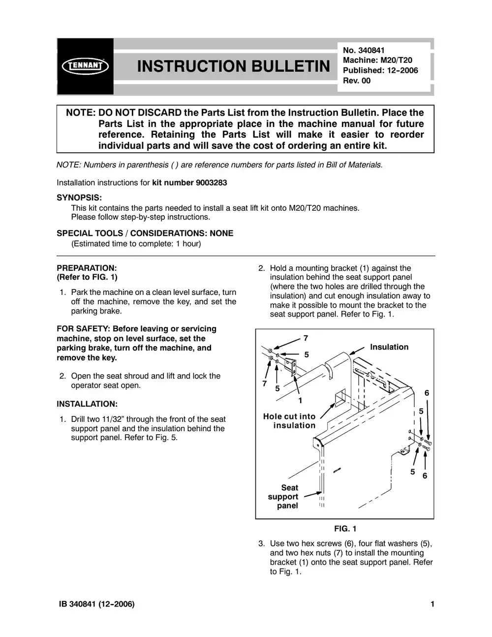
Tennant M20 instruction bulletin 340841, page 1 of 4
Page 1 of 4 SES ref PF-CJIN-SYN7‌‌​⁠‍‍‌​‌​‍‌⁠‌⁠​⁠‌‌⁠​​‍​⁠​‍‍​​​‌​‍‌​​​⁠⁠‌‌⁠⁠​⁠​‍​​​‍​‌‍‌⁠​‍⁠
Text of this page
INSTRUCTION NOTE: DO NOT DISCARD the Parts List Parts List in the appropriate pla reference. Retaining the Parts individual parts and will save the NOTE: Numbers in parenthesis ( ) are reference num Installation instructions for kit number TN4205425 SYNOPSIS: This kit contains the parts needed to install a seat Please follow step-by-step instructions. SPECIAL TOOLS / CONSIDERATIONS: NONE (Estimated time to complete: 1 hour) PREPARATION: (Refer to FIG. 1) 1. Park the machine on a clean level surface, turn off the machine, remove the key, and set the parking brake. FOR SAFETY: Before leaving or servicing machine, stop on level surface, set the parking brake, turn off the machine, and remove the key. 2. Open the seat shroud and lift and lock the operator seat open. INSTALLATION: 1. Drill two 11/32” through the front of the seat support panel and the insulation behind the support panel. Refer to Fig. 5. IB 340841 (12--2006) No. 340841 Machine: M20/T20 N BULLETIN Published: 12--2006 Rev. 00 from the Instruction Bulletin. Place the ace in the machine manual for future s List will make it easier to reorder e cost of ordering an entire kit. mbers for parts listed in Bill of Materials. t lift kit onto M20/T20 machines. 2. Hold a mounting bracket (1) against the insulation behind the seat support panel (where the two holes are drilled through the insulation) and cut enough insulation away to make it possible to mount the bracket to the seat support panel. Refer to Fig. 1. 7 Insulation 5 7 5 6 1 5 Hole cut into insulation 5 6 Seat support panel FIG. 1 3. Use two hex screws (6), four flat washers (5), and two hex nuts (7) to install the mounting bracket (1) onto the seat support panel. Refer to Fig. 1. 1
Tennant M20 instruction bulletin 340841, page 2 of 4
Page 2 of 4
Text of this page
4. Drill two 11/32” through the top of the seat plate and the insulation under the seat plate. Refer to Fig. 5. NOTE: It may be necessary to adjust seat position to make drilling holes into the seat plate weldment easier. 5. Hold a mounting bracket (1) against the insulation under the seat plate (where the two holes are drilled through the insulation) and cut enough insulation away to make it possible to mount the bracket to the seat plate. Refer to Fig. 2. 6 5 5 Seat plate 1 Insulation 5 5 7 7 FIG. 2 6. Use two hex screws (6), four flat washers (5), and two hex nuts (7) to install the mounting bracket (1) onto the seat plate weldment. Refer to Fig. 2. 2 7. Use two ball studs (3) and two hex nuts (4) to install the gas spring (2) onto the mounting brackets (1) installed in the previous steps. Refer to Fig. 3 and Fig. 4. Seat plate 4 1 Seat support panel 3 4 2 3 1 FIG. 3 FIG. 4 8. Open and close the operator seat/seat plate weldment to ensure the seat lift mechanism operates. IB 340841 (12--2006)
Tennant M20 instruction bulletin 340841, page 3 of 4
Page 3 of 4
Text of this page
Engine Side 49.95 (1.97 in) 2X ∅10 2X 53.7 (11/32 in) (2.11 in) 34.47 (1.35 in) Top of seat plate weldment Seat Shroud Side Seat Shroud Engine Side Side Front of seat support panel 2X ∅10 (11/32 in) FIG. 5 IB 340841 (12--2006) 3
Tennant M20 instruction bulletin 340841, page 4 of 4
Page 4 of 4
Text of this page
Bill of Materials for Seat Kit, Tennant Ref. Part No. Description o TN4205425 ) Seat Kit, Lift, CI [M20 & T Y 1 TN4193010 Bracket, Mtg Y 2 TN4031564 Gasspring, 175lb Y 3 TN4029776 Stud, Ball, .39D .31--16, G Y 4 TN4042967 Nut, Hex, Lock, .31--18, N Y 5 TN4042902 ) Washer, Flat, 0.38B 0.88 Y 6 TN4041943 Screw, Hex, M8 X 1.25 X Y 7 TN4041929 Nut, Hex, Lock, M8 X 1.2 TENNANT P. O. Bo Minneapolis, M 4 Lift, CI [M20 & T20]--TN4205425 Qty. T20] 1 2 1 Gasspring 2 NL, SS 2 8D .08, SS 8 X 25, SS 4 25, NL, SS 4 COMPANY ox 1452 MN 55440-1452 IB 340841 (12--2006)

Extinguisher Kit, Fire, CI [M20 & T20]

Tennant instruction bulletin 340813 rev. 00Published 11-2006Kit 9001316

What it’s for: Install a fire extinguisher onto M20/T20 machines.

  • Machines: M20, T20
  • M20: all
  • Power: gasoline, LPG and diesel

Time: 15 minutes · Special tools: NONE

Safety warnings (from the bulletin, word for word)

  • FOR SAFETY: Before leaving or servicing machine, stop on level surface, turn off machine, and remove key.

Parts

Parts for Tennant instruction bulletin 340813
ItemPart numberQtyDescriptionPrice
TN4019664Old # 90013161Extinguisher Kit, Fire, CI [M20 & T20]Kit$218.90/EA
1TN4035427Old # 253121Extinguisher, Fire, 1.5 Lb Dry$206.60/EA
2TN4027333Old # 3823202Screw, Pan, #12--16 X 0.50, F/Plastic$2.50/EA
3TN7000203Old # 10268981Shroud, Eng, Extinguisher, RwkCall for availability 800-440-6723

Bulletin PDF: Sign in to view or downloadSign in to download

Installation instructions (2 pages)
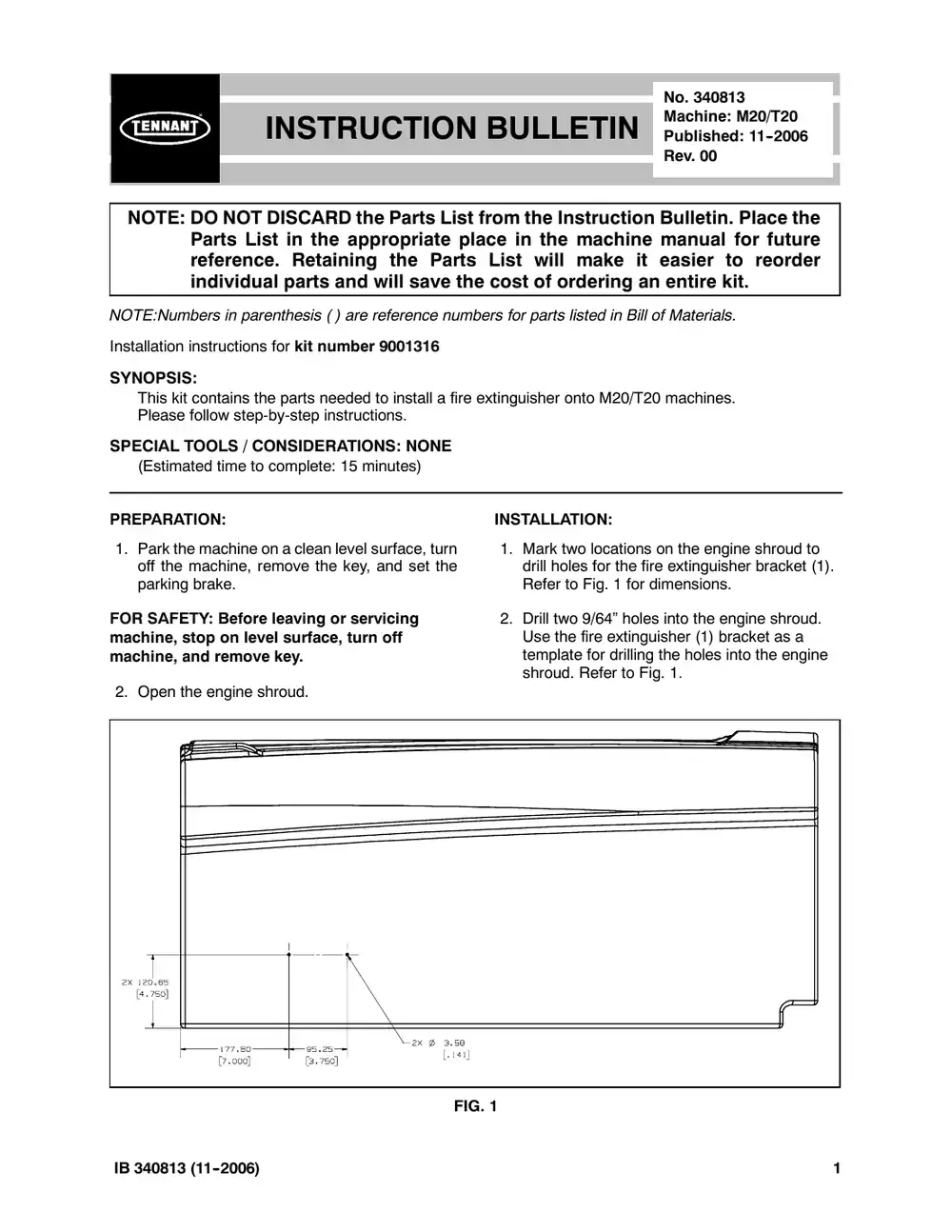
Tennant M20 instruction bulletin 340813, page 1 of 2
Page 1 of 2 SES ref PF-TQXB-5QZY‌‌​⁠‍‍‌​‌​‍‌⁠‌⁠​⁠‌‌⁠‍‌⁠‌‍‍​⁠​​​‌​‍‌​‌‌⁠​​​‌‍⁠‌⁠⁠⁠‍⁠⁠​⁠⁠‌​‍‍⁠
Text of this page
INSTRUCTION NOTE: DO NOT DISCARD the Parts List Parts List in the appropriate pla reference. Retaining the Parts individual parts and will save the NOTE:Numbers in parenthesis ( ) are reference numb Installation instructions for kit number TN4019664 SYNOPSIS: This kit contains the parts needed to install a fire Please follow step-by-step instructions. SPECIAL TOOLS / CONSIDERATIONS: NONE (Estimated time to complete: 15 minutes) PREPARATION: 1. Park the machine on a clean level surface, turn off the machine, remove the key, and set the parking brake. FOR SAFETY: Before leaving or servicing machine, stop on level surface, turn off machine, and remove key. 2. Open the engine shroud. FIG IB 340813 (11--2006) No. 340813 Machine: M20/T20 N BULLETIN Published: 11--2006 Rev. 00 from the Instruction Bulletin. Place the ace in the machine manual for future s List will make it easier to reorder e cost of ordering an entire kit. bers for parts listed in Bill of Materials. extinguisher onto M20/T20 machines. INSTALLATION: 1. Mark two locations on the engine shroud to drill holes for the fire extinguisher bracket (1). Refer to Fig. 1 for dimensions. 2. Drill two 9/64” holes into the engine shroud. Use the fire extinguisher (1) bracket as a template for drilling the holes into the engine shroud. Refer to Fig. 1. G. 1 1
Tennant M20 instruction bulletin 340813, page 2 of 2
Page 2 of 2
Text of this page
3. Use two pan screws (2) to mount the fire extinguisher (1) bracket to the engine shroud. Refer to Fig. 2. 4. Secure the fire extinguisher (1) into the bracket. Refer to Fig. 2. 1 2 Engine Cover FIG. 2 Bill of Materials for Extinguisher Kit, Fire, CI [M20 & T20]--TN4019664 Tennant Ref. Part No. Description Qty. o TN4019664 ) Extinguisher Kit, Fire, CI [M20 & T20] 1 Y 1 TN4035427 Extinguisher, Fire, 1.5 Lb Dry 1 Y 2 TN4027333 Screw, Pan, #12--16 X 0.50, F/Plastic 2 Y 3 TN7000203 Shroud, Eng, Extinguisher, Rwk 1 TENNANT COMPANY P. O. Box 1452 Minneapolis, MN 55440-1452 2 IB 340813 (11--2006)

Modif Kit, Hi--Amb Heat

Tennant instruction bulletin 340829 rev. 01Published 11-2006Kit 9003091

What it’s for: Install the M20 new product launch update kit.

  • Machines: M20
  • M20: all
  • Power: gasoline, LPG and diesel

Time: 5 hours · Special tools: Loctite® 2

Safety warnings (from the bulletin, word for word)

  • FOR SAFETY: Before leaving or servicing machine, stop on level surface, set parking brake, turn off machine, and remove key.
  • WARNING: Always disconnect battery cables from machine before working on electrical components.
  • FOR SAFETY: When servicing machine, avoid contact with hot engine coolant.
  • FOR SAFETY: When servicing machine, do not remove cap from radiator when engine is hot. Allow engine to cool.
  • WARNING: Moving belt and fan, Keep away.
  • FOR SAFETY: Avoid moving parts. Do not wear loose jackets, shirts, or sleeves when working on machine.

Parts

Parts for Tennant instruction bulletin 340829
ItemPart numberQtyDescriptionPrice
TN4016486Old # 90030911Modif Kit, Hi--Amb HeatKitCall for availability 800-440-6723
1TN4032250Old # 10322421Spacer, Fan [6600/6650 07]$181.00/EA
2TN4045369Old # 10350311Fan, Cooling, Pusher, 15.50D [2007]$249.90/EA
3TN4045064Old # 10336441Belt, Ribbed, 38.5L$73.00/EA
4TN4016796Old # 411861Washer, Flat, Belleville, .31$3.50/EA
5TN4041828Old # 167351Screw, Hex, M8 X 1.25 X 16, 8.8$3.40/EA
6TN4013994Old # 489983Screw, Flat, .38--16 X 1.00, Al$5.10/EA
7TN4041958Old # 091453Screw, Pan, M6 X 1.00 X 16, 4.8$3.40/EA
8TN4045039Old # 10334281Sheave, 5.00D [GM1.6L 2007]$459.70/EA
9TN4045378Old # 10350681Grill Wldt, Front$748.00/EA
10TN4045352Old # 10348781Insulation, Thermal, Hydraulic Blanket$145.60/EA
11TN4032036Old # 10315571Seal, Afmkt, Bulb, Str, 1.00D F/11ga 08 ft$159.70/EA
12TN4035239Old # 10171411Label Set, Hi Temp$30.80/EA
13TN4018310Old # 692341Clamp, Cable, Stl, 1.00D X 0.75W, 1 Hole$4.20/EA
14TN4034137Old # 324911Washer, Flat, 0.31, Std$2.50/EA
15TN4041844Old # 169311Screw, Hex, M8 X 1.25 X 20, 8.8$2.50/EA
16TN1021287Old # 10212871Panel, Shrd, Fan, Gas/LPGCall for availability 800-440-6723
17TN4193073Old # 10352221Skirt, Debris, Engine Radiator$50.70/EA
18TN4042902Old # 016853Washer, Flat, 0.38B 0.88D .08, SS$2.60/EA
19TN4193071Old # 10352141Bracket, Tube, Coolant [M20/T20]$8.89/EA
20TN4029699Old # 583661Clamp, Cable, Stl, 1.25D X 1.00W, 1 Hole$5.10/EA
21TN4041929Old # 087132Nut, Hex, Lock, M8 X 1.25, NL, SS$3.30/EA
22TN4041992Old # 097402Screw, Hex, M8 X 1.25 X 20, SS$3.30/EA
23TN4034138Old # 324921Washer, Flat, 0.38, Std$2.50/EA
24TN4016794Old # 411783Washer, Flat, 0.25, Fendr$2.50/EA
25TN4042426Old # 192071Label, Info, Hyd Fluid, NA/CECall for availability 800-440-6723
26TN4030823Old # 3313811Manual, Parts [M20 Gas/LPG En/Jp]*$157.80/EA

Bulletin PDF: Sign in to view or downloadSign in to download

Installation instructions (10 pages)
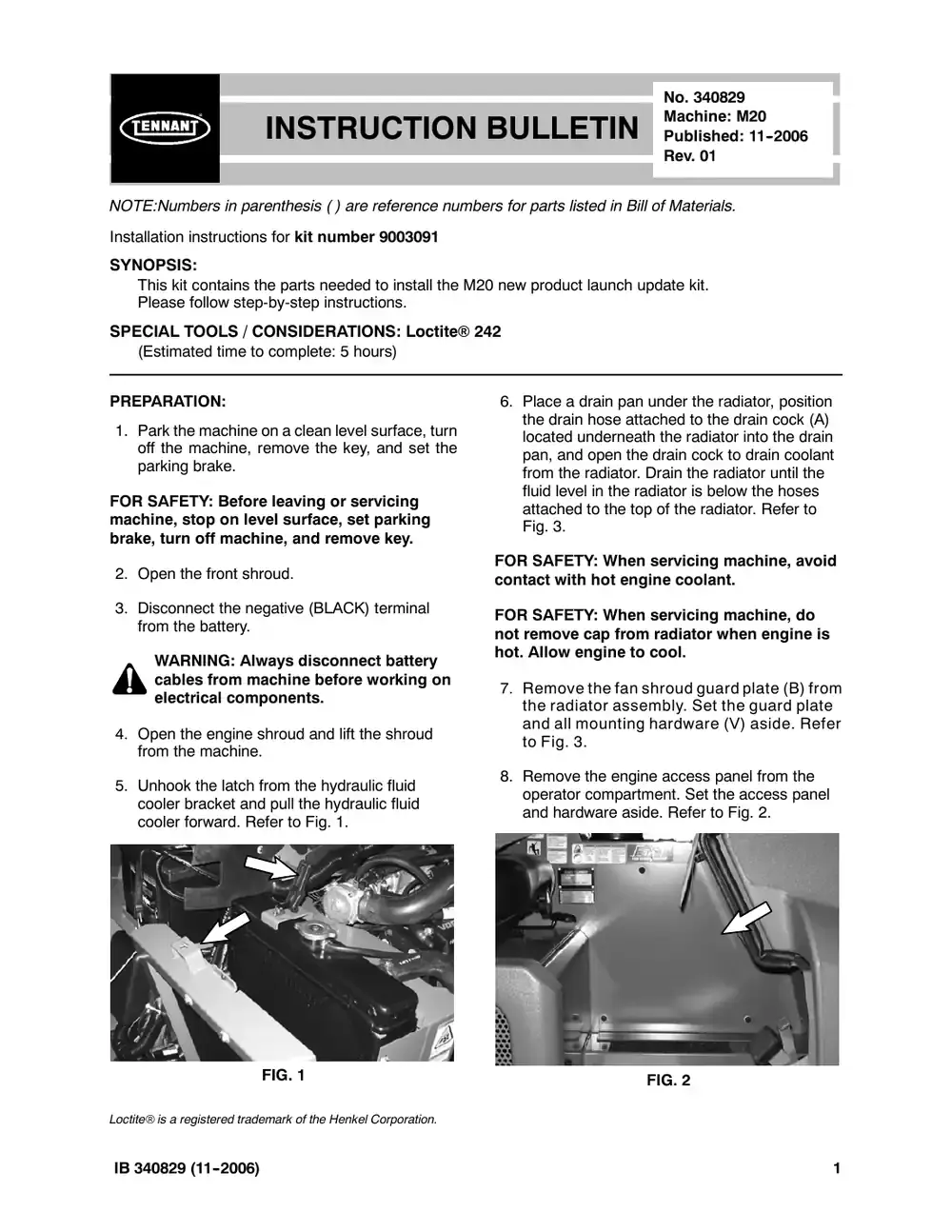
Tennant M20 instruction bulletin 340829, page 1 of 10
Page 1 of 10 SES ref PF-LR6M-2NDT‌‌​⁠‍‍‌​‌​‍‌⁠‌⁠​⁠‌‌⁠​‍‌⁠‌⁠⁠‍​​​‌​‍‌​‌‍​⁠‍‍‌‌​‌​⁠⁠‍‍⁠​​‌‍‌⁠‌‌
Text of this page
INSTRUCTION NOTE:Numbers in parenthesis ( ) are reference numb Installation instructions for kit number TN4016486 SYNOPSIS: This kit contains the parts needed to install the M Please follow step-by-step instructions. SPECIAL TOOLS / CONSIDERATIONS: Loctite® 2 (Estimated time to complete: 5 hours) PREPARATION: 1. Park the machine on a clean level surface, turn off the machine, remove the key, and set the parking brake. FOR SAFETY: Before leaving or servicing machine, stop on level surface, set parking brake, turn off machine, and remove key. 2. Open the front shroud. 3. Disconnect the negative (BLACK) terminal from the battery. WARNING: Always disconnect battery cables from machine before working on electrical components. 4. Open the engine shroud and lift the shroud from the machine. 5. Unhook the latch from the hydraulic fluid cooler bracket and pull the hydraulic fluid cooler forward. Refer to Fig. 1. FIG. 1 Loctite® is a registered trademark of the Henkel Corporation. IB 340829 (11--2006) No. 340829 Machine: M20 N BULLETIN Published: 11--2006 Rev. 01 bers for parts listed in Bill of Materials. M20 new product launch update kit. 242 6. Place a drain pan under the radiator, position the drain hose attached to the drain cock (A) located underneath the radiator into the drain pan, and open the drain cock to drain coolant from the radiator. Drain the radiator until the fluid level in the radiator is below the hoses attached to the top of the radiator. Refer to Fig. 3. FOR SAFETY: When servicing machine, avoid contact with hot engine coolant. FOR SAFETY: When servicing machine, do not remove cap from radiator when engine is hot. Allow engine to cool. 7. Remove the fan shroud guard plate (B) from the radiator assembly. Set the guard plate and all mounting hardware (V) aside. Refer to Fig. 3. 8. Remove the engine access panel from the operator compartment. Set the access panel and hardware aside. Refer to Fig. 2. FIG. 2 1
Tennant M20 instruction bulletin 340829, page 2 of 10
Page 2 of 10
Text of this page
9. Remove the air deflector plate (P) from the fan panel shroud (D). Set the hex screws (Q) aside. Discard the air deflector plate. Refer to Fig. 3. 10. Disconnect hoses (F) and (G) from the radiator. Position hoses out of the way so coolant does not leak out onto the engine or the floor. Set the hose clamps aside. Refer to Fig. 3. 11. Remove the two nuts and washers (H) holding the bottom of the radiator to the machine. Set the the nuts and washers aside. Do Not lose the washers. Refer to Fig. 3. 12. Remove the hardware (C) holding the fan shroud panel (D) to the radiator (E). Set all removed hardware (C) aside. Refer to Fig. 3. R T D C S E FIG 2 13. Carefully move the radiator forward and out of the way of the fan assembly. Do not completely remove the radiator from the machine. Refer to Fig. 3 14. Use a 5/16” Allen wrench to remove the hardware (I) holding the fan (J) onto the engine and remove the fan. Discard the fan and hardware. Refer to Fig. 4. 15. Remove the fan shroud panel (D) from the machine. Remove the latch assembly (R) and radiator seal assembly (S) from the fan panel shroud. Set the latch assembly, radiator seal seal, and mounting hardware (T) and (U) aside. Discard the fan shroud panel. Refer to Fig. 3. U G F B V C P Q A H G. 3 IB 340829 (11--2006)
Tennant M20 instruction bulletin 340829, page 3 of 10
Page 3 of 10
Text of this page
16. Relieve the fan belt tension at the alternator (K) and remove the fan belt (L) from the machine. Discard the fan belt. Refer to Fig. 4. M O N FIG INSTALLATION: 1. Use the saved hardware (T) and (U) to attach the latch assembly (R) and radiator seal assembly (S) onto the new fan shroud panel (16). Refer to Fig. 3. 2. Apply Loctite 242 to the saved hex screws (Q) and use the hex screws (Q) and three fender washers (24) to install the radiator debris skirt (17) onto the fan shroud panel (16). Refer to Fig. 5. Q 16 17 24 FIG. 5 IB 340829 (11--2006) 17. Remove the spacer (M) and sheave (O) from the fan base (N) If necessary, use a chisel and hammer to knock the spacer (M) loose from the engine shaft (N). Be careful to not damage the fan base if using a chisel. Refer to Fig. 4. J I L K G. 4 3. Place the new fan shroud panel (16) next to the radiator, where the old fan shroud panel was previously installed. Refer to Fig. 3. 4. Align the holes in the new sheave (8) and fan spacer (1) with the holes in the fan base (N) and slide the sheave and fan spacer onto the fan base. Refer to Fig. 6. 5. Apply Loctite 242 to the three flat screws (6) and use the flat screws to secure the fan spacer (1) to the sheave (8). Torque to 21.7--28.5 Nm (16--21 ft. lbs). Refer to Fig. 6. 6. Install the new belt (3) onto the engine and tighten the belt so there is only a slight bit of tension. Refer to Fig. 6. 7. Install the new fan (2) onto the fan spacer (1). Be sure the nuts holding the fan together point out towards the radiator and the three threaded holes in the fan are aligned with the three threaded holes in the fan spacer. Refer to Fig. 6. 3
Tennant M20 instruction bulletin 340829, page 4 of 10
Page 4 of 10
Text of this page
8. Apply Loctite 242 to the hex screw (5) and use the hex screw and belleville washer (4) to secure the fan (2) onto the fan base. Torque to 13--16.5 Nm (9.6--12.2 ft. lbs). Be sure the three threaded holes in the fan remain aligned with the three threaded holes in the fan spacer (1). Refer to Fig. 6. 9. Apply Loctite 242 to the three pan screws (7) and use the pan screws to secure the fan (2) to the fan spacer (1). Torque to 3.3--4.3 Nm (2.4--3.2 ft. lbs). Refer to Fig. 6. 10. Use the saved nuts and washers (H) to reinstall the radiator onto the machine. Refer to Fig. 3. 11. Use the saved hardware (C) to reinstall the shroud panel (D) onto the radiator. If necessary, loosen the latch assembly (R) to make installing the inner hardware easier. Do not completely tighten the hardware. Refer to Fig. 3. 3 8 N FIG 4 12. Be sure fan is centered in shroud before tightening the hardware. Manually spin the fan by hand to ensure the fan does not hit the radiator or the shroud. 13. Tighten the belt (3). Refer to Fig. 6. 14. Reattach the hoses (F) and (G) removed from the top of the radiator. Refer to Fig. 3. 15. Use saved hardware (V) to install the fan shroud guard plate (B) onto the fan shroud panel (16). Refer to Fig. 3. 16. Reinstall the engine shroud. 4 2 5 1 7 6 G. 6 IB 340829 (11--2006)
Tennant M20 instruction bulletin 340829, page 5 of 10
Page 5 of 10
Text of this page
17. Remove the grill from the front shroud. Save all hardware used to secure the old grill onto the shroud. Discard the grill. Refer to Fig. 7. 18. Use the saved hardware to install the new grill (9) onto the front shroud. Refer to Fig. 7. 19. Apply Loctite 242 to the seals (11) and install the seals onto the inner portion of the grill (9). Refer to Fig. 7. FIG 20. Remove the cap from the hydraulic reservoir. Refer to Fig. 8. 10 FIG. 8 21. Install the thermal insulation blanket (10) over the hydraulic reservoir and reinstall the cap onto the hydraulic reservoir. Refer to Fig. 8. IB 340829 (11--2006) 11 9 G. 7 22. Install the labels (12) and (25) onto the hydraulic reservoir. Refer to Fig. 9. FIG. 9 23. Reconnect the battery cables to the batteries. 24. Refill the coolant system. Refer to the ELIMINATE AIR FROM AND FILL THE COOLANT SYSTEM section of this IB for how to bleed and fill the coolant system. 5
Tennant M20 instruction bulletin 340829, page 6 of 10
Page 6 of 10
Text of this page
PROPEL HOSE ADJUSTMENT, MAIN WIRE HARNESS CLAMP INSTALLATION, AND COOLANT TUBE CLAMP INSTALLATION: 1. Start the machine and turn the steering wheel completely to the left and then to the right. Inspect the portion of the hydraulic propel hose near the alternator. The hose must not touch or be rubbing against the alternator, alternator bracket, or hardware when the steering wheel is turned in either direction. Proceed to Step 2 if the hoses are touching or rubbing against any part of the alternator. Proceed to Step 6 if the hoses are not rubbing against or touching the alternator. Refer to Fig. 10. FIG. 10 2. Disconnect the battery cables from the batteries. 3. Lift the operator seat and remove the LPG tank (if machine is equipped with LPG fuel system) to access the hose clamp located on the inner side of the operator compartment. Refer to Fig. 11. FIG. 11 6 4. Slightly loosen the hose clamp and reposition the hydraulic propel hose so the yellow line on the hose is positioned either 1” above or below the clamp. Refer to Fig. 11 and Fig. 12. FIG. 12 5. Retighten the hose clamp loosened in the previous step. Refer to Fig. 11 or Fig. 12. 6. Insert the main wire harness into the cable clamp (13) and use a hex screw (15) and flat washer (14) to secure the main wire harness to the engine, away from the alternator. Refer to Fig. 13. 15 14 13 FIG. 13 IB 340829 (11--2006)
Tennant M20 instruction bulletin 340829, page 7 of 10
Page 7 of 10
Text of this page
7. Remove the one hex screw and flat washers holding the alternator bracket to the machine. Set the hex nut aside. Discard the flat washer. Refer to Fig. 14. Discard flatwasher Alternator bracket Remove and set hex screw aside FIG. 14 8. Stretch the loose end of the radiator debris skirt (17) tight over to where the hex screw was removed in the previous step and use the saved hex screw and a flat washer (23) to secure the radiator debris skirt to the alternator bracket. The radiator debris skirt must be stretched tight so it does not get sucked into the fan or belt. Refer to Fig. 15. 23 FIG. 15 IB 340829 (11--2006) 9. Inspect the red boot on the alternator. The boot should be firmly attached to and completely cover the terminal. Tighten a wire tie around the boot to secure the boot onto the wires attached to the alternator. Refer to Fig. 16. FIG. 16 10. Connect the battery cables to the batteries. 11. Start the machine and turn the steering wheel as far to the left as possible. 12. Install the cable clamp (20) onto the lower coolant tube and use a hex screw (22) a hex nut (21), and a washer (18) to loosely install the coolant tube bracket (19) onto the cable clamp (20). Refer to Fig. 17 and Fig. 18. FIG. 17 FIG. 18 7
Tennant M20 instruction bulletin 340829, page 8 of 10
Page 8 of 10
Text of this page
13. Drill a 3/8” hole through the hole in the coolant tube bracket (19) and into the frame of the machine. Refer to Fig. 18. 14. Use a hex screw (22) a hex nut (21), and a washer (18) to secure the coolant tube bracket (19) to the frame of the machine. Also tighten the hex screw (22) and hex nut (21) to firmly secure the cable clamp (20) to the coolant tube bracket (19). Refer to Fig. 19. FIG. 19 INSPECT ANGLE OF FITTING AT M1 ON SCRUB BLOCK: 15. Remove the port cover from Port G1 on the the scrub block. Refer to Fig. 20. FIG. 20 8 16. Hold a quick--disconnect fitting up to Port G1 on the scrub block. DO NOT install the quick--disconnect fitting into the port. The fitting in Port M1 on the scrub block should be positioned next to the quick--disconnect fitting held onto Port G1 as shown in Fig. 21. FIG. 21 17. If necessary, rotate the fitting in Port M1 on the scrub block toward the quick--disconnect fitting. Allow just enough clearance to engage/ disengage the quick--disconnect fitting. Refer to Fig. 21. 18. Reinstall the access panel into the operator compartment. Refer to Fig. 2. 19. Discard the old parts manual (REV. 00) and replace it with the new updated parts manual (REV. 01) (26). 20. Reconnect the battery cables to the batteries. 21. Start and test the machine. 22. If the fitting in Port M1 on the scrub block was rotated, check the fitting for leaks. Refer to Fig. 21. IB 340829 (11--2006)
Tennant M20 instruction bulletin 340829, page 9 of 10
Page 9 of 10
Text of this page
ELIMINATE AIR FROM COOLANT SYSTEM AND FILL COOLANT SYSTEM: FOR SAFETY: When servicing machine, avoid contact with hot engine coolant. FOR SAFETY: When servicing machine, do not remove cap from radiator when engine is hot. Allow engine to cool. 1. Position a bucket or drain pan underneath the clear PVC tubing attached to the drain cock to prevent the fluid draining from the drain cock from running onto the floor. 2. Open the drain cock. Refer to Fig. 22 for the location of the drain cock on LPG machines and Fig. 23 for the location of the drain cock on gasoline machines. FIG. 22 FIG. 23 3. Remove the cap from the radiator and slowly pour coolant into the radiator. Continue pouring coolant into the radiator until a steady solid stream of coolant drains from the drain cock. IB 340829 (11--2006) 4. Quickly close the drain cock while the steady solid stream of coolant is draining. 5. Remove the cap from the overflow tank and pour coolant into the overflow tank until the level reaches the “FULL WHEN COLD” mark. Reinstall the cap back onto the overflow tank. 6. Pour additional coolant into the radiator. Note: It should be possible to add coolant to the radiator. If the radiator appears full, there may still be air in the system. Repeat Step 2 through Step 6. 7. Ensure radiator cap IS NOT on the radiator. If necessary, remove the cap from the radiator. 8. Start the engine and allow the machine to run for approximately 5 minutes. WARNING: Moving belt and fan, Keep away. FOR SAFETY: Avoid moving parts. Do not wear loose jackets, shirts, or sleeves when working on machine. 9. Turn off the engine. 10. Check the coolant level in the radiator. If necessary, pour additional coolant into the radiator. 11. Reinstall the radiator cap onto the radiator. 12. Start engine and allow machine to run for approximately 5 minutes. If the engine warning light comes on, repeat the entire procedure. If the engine warning light comes on after procedure is repeated, check the codes. Refer to the service manual for instructions how to check codes. SERIOUS ENGINE DAMAGE COULD RESULT IF THIS PROCEDURE IS NOT FOLLOWED! 9
Tennant M20 instruction bulletin 340829, page 10 of 10
Page 10 of 10
Text of this page
Bill of Materials for Modif Kit, Hi--Amb Heat--TN4016486 Tennant Ref. Part No. Description Qty. o TN4016486 ) Modif Kit, Hi--Amb Heat 1 Y 1 TN4032250 Spacer, Fan [6600/6650 07] 1 Y 2 TN4045369 Fan, Cooling, Pusher, 15.50D [2007] 1 Y 3 TN4045064 Belt, Ribbed, 38.5L 1 Y 4 TN4016796 Washer, Flat, Belleville, .31 1 Y 5 TN4041828 ) Screw, Hex, M8 X 1.25 X 16, 8.8 1 Y 6 TN4013994 Screw, Flat, .38--16 X 1.00, Al 3 Y 7 TN4041958 Screw, Pan, M6 X 1.00 X 16, 4.8 3 Y 8 TN4045039 Sheave, 5.00D [GM1.6L 2007] 1 Y 9 TN4045378 Grill Wldt, Front 1 Y 10 TN4045352 ) Insulation, Thermal, Hydraulic Blanket 1 Y 11 TN4032036 Seal, Afmkt, Bulb, Str, 1.00D F/11ga 08 ft 1 Y 12 TN4035239 Label Set, Hi Temp 1 Y 13 TN4018310 Clamp, Cable, Stl, 1.00D X 0.75W, 1 Hole 1 Y 14 TN4034137 Washer, Flat, 0.31, Std 1 Y 15 TN4041844 ) Screw, Hex, M8 X 1.25 X 20, 8.8 1 Y 16 TN1021287 Panel, Shrd, Fan, Gas/LPG 1 Y 17 TN4193073 Skirt, Debris, Engine Radiator 1 Y 18 TN4042902 Washer, Flat, 0.38B 0.88D .08, SS 3 Y 19 TN4193071 Bracket, Tube, Coolant [M20/T20] 1 Y 20 TN4029699 ) Clamp, Cable, Stl, 1.25D X 1.00W, 1 Hole 1 Y 21 TN4041929 Nut, Hex, Lock, M8 X 1.25, NL, SS 2 Y 22 TN4041992 Screw, Hex, M8 X 1.25 X 20, SS 2 Y 23 TN4034138 Washer, Flat, 0.38, Std 1 Y 24 TN4016794 Washer, Flat, 0.25, Fendr 3 Y 25 TN4042426 ) Label, Info, Hyd Fluid, NA/CE 1 Y 26 TN4030823 Manual, Parts [M20 Gas/LPG En/Jp]* 1 *Discard old parts manual and replace it with new updated parts manual (26). TENNANT COMPANY P. O. Box 1452 Minneapolis, MN 55440-1452 10 IB 340829 (11--2006)

Switch Kit, Replmt, Thermostat, Eng

Tennant instruction bulletin 9005795 rev. 00Published 12-2008Kit 9005789

What it’s for: Replace the thermostat switch on ATLV4300, 6400, 6600/6650, 6200, M20, T20, M30, and S30 machines.

  • Machines: M20, M30, S30, T20
  • M20: all
  • Power: gasoline, LPG and diesel

Time: 1 hour · Special tools: NONE

Safety warnings (from the bulletin, word for word)

  • FOR SAFETY: Before leaving or servicing machine, stop on level surface, turn off machine, and remove key.
  • WARNING: Always disconnect battery cables from machine before working on electrical components.

Parts

Parts for Tennant instruction bulletin 9005795
ItemPart numberQtyDescriptionPrice
TN4014459Old # 90057891Switch Kit, Replmt, Thermostat, EngKitCall for availability 800-440-6723
1TN4040710Old # 10507571Switch, Thermostat, Water$128.60/EA
2TN4030581Old # 1300972Terminal, Fem, .25 X 0.32 16--14 Ga, F--InsCall for availability 800-440-6723

Bulletin PDF: Sign in to view or downloadSign in to download

Installation instructions (2 pages)
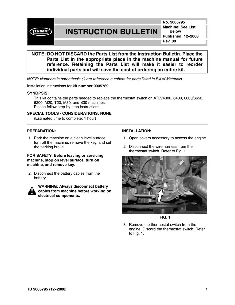
Tennant M20 instruction bulletin 9005795, page 1 of 2
Page 1 of 2 SES ref PF-ZGW6-DG5F‌‌​⁠‍‍‌​‌​‍‌⁠‌⁠​⁠‌‌⁠‌⁠‌​⁠‌⁠​​​​‌​‍‌​‍⁠‌‌⁠‍⁠‌⁠⁠‌‍‍‌‌‍⁠‌⁠‌⁠‍‌​
Text of this page
INSTRUCTION NOTE: DO NOT DISCARD the Parts List Parts List in the appropriate pla reference. Retaining the Parts individual parts and will save the NOTE: Numbers in parenthesis ( ) are reference num Installation instructions for kit number TN4014459 SYNOPSIS: This kit contains the parts needed to replace the t 6200, M20, T20, M30, and S30 machines. Please follow step-by-step instructions. SPECIAL TOOLS / CONSIDERATIONS: NONE (Estimated time to complete: 1 hour) PREPARATION: 1. Park the machine on a clean level surface, turn off the machine, remove the key, and set the parking brake. FOR SAFETY: Before leaving or servicing machine, stop on level surface, turn off machine, and remove key. 2. Disconnect the battery cables from the battery. WARNING: Always disconnect battery cables from machine before working on electrical components. IB 9005795 (12--2008) No. 9005795 Machine: See List N BULLETIN Below Published: 12--2008 Rev. 00 from the Instruction Bulletin. Place the ace in the machine manual for future s List will make it easier to reorder e cost of ordering an entire kit. mbers for parts listed in Bill of Materials. thermostat switch on ATLV4300, 6400, 6600/6650, INSTALLATION: 1. Open covers necessary to access the engine. 2. Disconnect the wire harness from the thermostat switch. Refer to Fig. 1. FIG. 1 3. Remove the thermostat switch from the engine. Discard the thermostat switch. Refer to Fig. 1. 1
Tennant M20 instruction bulletin 9005795, page 2 of 2
Page 2 of 2
Text of this page
4. Compare the thermostat switch connector on 6. Connect the wire harness to the thermostat the main wire harness with the terminal on the switch (1). Refer to Fig. 3. new thermostat switch (1). If the connector on the wire harness does not fit the terminal on the thermostat switch (1), cut the connector from the harness and install a new connector (2) onto the harness. 5. Install the thermostat switch (1) onto the engine. Refer to Fig. 2. FIG. 3 FIG. 2 Bill of Materials for Switch Kit, Replmt, Thermostat, Eng -- TN4014459 Tennant Ref. Part No. Description Qty. o TN4014459 ) Switch Kit, Replmt, Thermostat, Eng 1 Y 1 TN4040710 Switch, Thermostat, Water 1 Y 2 TN4030581 Terminal, Fem, .25 X 0.32 16--14 Ga, F--Ins 2 TENNANT COMPANY P. O. Box 1452 Minneapolis, MN 55440-1452 2 IB 9005795 (12--2008)

Replace the PCV grommet on M20 / T20 / M30 / S30 machines equipped wit

Tennant instruction bulletin 328338 rev. 00Published 04-2013Kit 322365

What it’s for: Replace the PCV grommet on M20 / T20 / M30 / S30 machines equipped with Mitsubishi engines.

  • Machines: M20, M30, S30, T20
  • M20: all
  • Power: Gasoline, LPG
  • Engine: Mitsubishi
  • Applies to: Mitsubishi engine

Time: 30 minutes · Special tools: NONE

Safety warnings (from the bulletin, word for word)

  • FOR SAFETY: Before leaving or servicing machine, stop on level surface, turn off machine, set parking brake, and remove key.

Parts

Parts for Tennant instruction bulletin 328338
ItemPart numberQtyDescriptionPrice
TN4183662Old # 3223651KitKitCall for availability 800-440-6723
TN4183662Old # 3223651CS, Valve Kit, [M20/T20/M30/S30] CICall for availability 800-440-6723
1TN4191416Old # 3152531CS, VR, Valve, Gasket, PCVCall for availability 800-440-6723

Bulletin PDF: Sign in to view or downloadSign in to download

Installation instructions (4 pages)
Tennant M20 instruction bulletin 328338, page 1 of 4
Page 1 of 4 SES ref PF-PO5S-BWCW‌‌​⁠‍‍‌​‌​‍‌⁠‌⁠​⁠‌‌⁠​‌‌​​​‌⁠​​​‌​‍‌​​⁠​‌‌​​‍‍​‍⁠​⁠⁠‌‍⁠⁠⁠‍​‍⁠
Text of this page
INSTRUCTION B NOTE: DO NOT DISCARD the Parts List Parts List in the appropriate pla reference. Retaining the Parts individual parts and will save the NOTE: Numbers in parenthesis ( ) are reference num Installation instructions for kit number TN4183662 SYNOPSIS: This kit contains the parts needed to replace the P equipped with Mitsubishi engines. Please follow step-by-step instructions. SPECIAL TOOLS / CONSIDERATIONS: NONE (Estimated time to complete: 30 minutes) PROTECT THE ENVIRON Please dispose of packagin and hazardous fluids in an to local waste disposal regu Always remember to recyc PREPARATION: 1. Park the machine on a clean level surface, turn off the machine, set the parking brake, and remove the key. FOR SAFETY: Before leaving or servicing machine, stop on level surface, turn off machine, set parking brake, and remove key. IB 328338 (04- 2013) No. 328338 Machine: M20 / T20 / BULLETIN M30 / S30 Published: 04- 2013 Rev. 00 from the Instruction Bulletin. Place the ace in the machine manual for future s List will make it easier to reorder e cost of ordering an entire kit. mbers for parts listed in Bill of Materials. PCV grommet on M20 / T20 / M30 / S30 machines NMENT ng materials, old machine components, environmentally safe manner according ulations. cle. 1
Tennant M20 instruction bulletin 328338, page 2 of 4
Page 2 of 4
Text of this page
INSTALLATION: 1. Open all shrouds necessary to access the top of the engine where the PCV valve is located. (Fig. 1) FIG. 1 2. Unplug the PCV valve from the engine. Remove and discard the washer (if equipped). (Fig. 2) FIG. 2 2 3. Remove the existing PCV grommet (thin top) from the engine. Discard the removed PCV grommet. (Fig. 3) Old New grommet grommet has has thinner thicker top. top. FIG. 3 4. Install the new grommet (thicker top) into the engine, then install the PCV valve into the grommet. (Fig. 4) FIG. 4 IB 328338 (04- 2013)
Tennant M20 instruction bulletin 328338, page 3 of 4
Page 3 of 4
Text of this page
INSPECTING FOR OIL LEAKS: 1. Open the engine shroud and inspect the oil filter adaptor fittings for leaks and tightness. (Fig. 5) FIG. 5 2. M20/M30/T20 only: Remove the access panel on the lower left side of the operator station. Inspect the oil adaptor plate, hoses, plug, and fittings for leaks. (Fig. 6 / Fig. 7) FIG. 6 View from the bottom showing the plug. FIG. 7 IB 328338 (04- 2013) S30 only: Open the rear engine shrouds. Items to be inspected are located behind the left shroud. Inspect the oil adaptor plate, hoses, plug, and fittings for leaks. (Fig. 8) FIG. 8 3. Tighten any loose hoses / fittings. (Fig. 6 / Fig. 7 / Fig. 8) 4. Check the engine oil level. Add oil as necessary. 5. Start and test engine. 3
Tennant M20 instruction bulletin 328338, page 4 of 4
Page 4 of 4
Text of this page
Bill Of Materials For CS, Valve Kit, [M20/T20/M30/S30] CI - TN4183662 1 Tennant Ref. Part No. Description Qty. o TN4183662 ) CS, Valve Kit, [M20/T20/M30/S30] CI 1 Y 1 TN4191416 CS, VR, Valve, Gasket, PCV 1 TENNANT COMPANY P. O. Box 1452 Minneapolis, MN 55440-1452 4 IB 328338 (04- 2013)

Sheave Assy, Kit, Repair

Tennant instruction bulletin 9007105 rev. 00Published 10-2009Kit 9007088

What it’s for: Replace the sheave assembly on M20, M30, T20, S30, 8200/8210, 7400, and 6600/6650 machines equipped with GM 1.6L Gas or LP engines.

  • Machines: M20, M30, S30, T20
  • M20: SN 000000–007999
  • Power: Gasoline, LPG
  • Engine: GM 1.6L
  • Applies to: GM engine

Time: 3 hours · Special tools: NONE

Safety warnings (from the bulletin, word for word)

  • FOR SAFETY: Before leaving or servicing machine, stop on level surface, turn off machine, and remove key.

Parts

Parts for Tennant instruction bulletin 9007105
ItemPart numberQtyDescriptionPrice
TN4011832Old # 90070881Sheave Assy, Kit, RepairKit$294.80/EACall for availability
1TN4038776Old # 10554251SHEAVE, MACH [GM1.6L]Call for availability 800-440-6723
2TN4038767Old # 10553811PLATE WLDT, FAN, HUB [GM 1.6L]$87.00/EACall for availability
3TN4038766Old # 10553772BEARING, BALL, 20MM B 42MM D 12MM W$12.60/EA
4TN4039390Old # 211952SCREW, HEX, .38--16 X 0.75, G5$3.40/EA
5TN4037922Old # 10145631WASHER, FLAT, 0.40B 1.12D .12, SS$5.80/EA
6TN4034134Old # 324851WASHER, FLAT, 0.38, SAE$2.50/EA
7TN4041844Old # 169312SCREW, HEX, M8 X 1.25 X 20, 8.8$2.50/EA
8TN4015595Old # 393492WASHER, FLAT, 0.31, SAE$2.50/EA

Bulletin PDF: Sign in to view or downloadSign in to download

Installation instructions (4 pages)
Tennant M20 instruction bulletin 9007105, page 1 of 4
Page 1 of 4 SES ref PF-5C47-5VAK‌‌​⁠‍‍‌​‌​‍‌⁠‌⁠​⁠‌‌⁠‌⁠‍⁠‍‍⁠​​​​‌​‍‌​​⁠⁠⁠‍‍​‌‍​‍‌​⁠‍‍⁠⁠‍⁠‌⁠​⁠
Text of this page
INSTRUCTION NOTE: DO NOT DISCARD the Parts List Parts List in the appropriate pla reference. Retaining the Parts individual parts and will save the NOTE: Numbers in parenthesis ( ) are reference num Installation instructions for kit number TN4011832 SYNOPSIS: This kit contains the parts needed to replace the s 8200/8210, 7400, and 6600/6650 machines equip Please follow step-by-step instructions. SPECIAL TOOLS / CONSIDERATIONS: NONE (Estimated time to complete: 3 hours) PREPARATION: 1. Park the machine on a clean level surface, turn off the machine, remove the key, and set the parking brake. FOR SAFETY: Before leaving or servicing machine, stop on level surface, turn off machine, and remove key. 2. Open and / or remove shrouds / covers necessary to access the engine. INSTALLATION: 1. Remove the fan shroud / belt guard from the machine. Set the fan shroud / belt guard and all mounting hardware aside. 2. Drain the antifreeze from the coolant system. Dispose of the drained antifreeze. NOTE: Antifreeze is an environmentally hazardous chemical. Dispose of antifreeze in an environmentally safe manner according to local waste disposal regulations. 3. Remove the radiator from the machine. Set the radiator and all mounting hardware aside. IB 9007105 (10--2009) No. 9007105 Machine: See Below N BULLETIN Published: 10--2009 Rev. 00 from the Instruction Bulletin. Place the ace in the machine manual for future s List will make it easier to reorder e cost of ordering an entire kit. mbers for parts listed in Bill of Materials. sheave assembly on M20, M30, T20, S30, pped with GM 1.6L Gas or LP engines. 1
Tennant M20 instruction bulletin 9007105, page 2 of 4
Page 2 of 4
Text of this page
4. Remove the cooling fan assembly and spacer from the engine. Set the fan assembly, spacer, and all mounting hardware aside. Refer to Fig. 1. 5. Remove the engine belt from the machine. Set the engine belt aside. Refer to Fig. 1. 6. Remove the sheave and fan hub pulley from the machine. Discard the sheave, fan hub pulley, and all mounting hardware. Refer to Fig. 1. Remove a set as Remove and discard FIG 2 Remove and set aside and side G. 1 IB 9007105 (10--2009)
Tennant M20 instruction bulletin 9007105, page 3 of 4
Page 3 of 4
Text of this page
2 FIG 7. Use a two hex screws (4), one hex screw (7), two flat washers (8), and one flat washer (6) to install the fan hub plate (2) onto the engine. Refer to Fig. 2. 8. Press both ball bearings (3) into the sheave (1). Refer to Fig. 2. 9. Slide the sheave assembly onto the fan hub plate (2). Refer to Fig. 2. 10. Use a hex screw (4) and a flat washer (5) to secure the sheave assembly onto the fan hub plate (2). Refer to Fig. 2. 11. Position the engine belt onto the sheave assembly, alternator, and harmonic balancer. 12. Reinstall the cooling fan assembly and spacer onto the machine. IB 9007105 (10--2009) 7 8 3 4 5 3 8 1 7 4 6 G. 2 13. Tighten the engine belt to the appropriate tension. Refer to the Maintenance section of the Operators manual for the correct tension. 14. Check the engine belt alignment. If necessary, make necessary adjustments to properly align the belt. 15. Reinstall the fan shroud / belt guard onto the radiator. 16. Reinstall the radiator onto the machine. 17. Refill the engine cooling system with the appropriate amount of fresh antifreeze. Refer to the Specifications section of the Operators Manual for the required amount. NOTE: Be sure all air is purged from the cooling system before operating the machine. 18. Start and test the machine. Observe the coolant system for leaks. 3
Tennant M20 instruction bulletin 9007105, page 4 of 4
Page 4 of 4
Text of this page
Bill of Materials for Sheave Assy, Kit, Repair -- TN4011832 Tennant Ref. Part No. Description Qty. o TN4011832 ) SHEAVE ASSY, KIT, REPAIR 1 Y 1 TN4038776 SHEAVE, MACH [GM1.6L] 1 Y 2 TN4038767 PLATE WLDT, FAN, HUB [GM 1.6L] 1 Y 3 TN4038766 BEARING, BALL, 20MM B 42MM D 12MM W 2 Y 4 TN4039390 SCREW, HEX, .38--16 X 0.75, G5 2 Y 5 TN4037922 ) WASHER, FLAT, 0.40B 1.12D .12, SS 1 Y 6 TN4034134 WASHER, FLAT, 0.38, SAE 1 Y 7 TN4041844 SCREW, HEX, M8 X 1.25 X 20, 8.8 2 Y 8 TN4015595 WASHER, FLAT, 0.31, SAE 2 TENNANT COMPANY P. O. Box 1452 Minneapolis, MN 55440-1452 4 IB 9007105 (10--2009)

Motor Kit, Side Brush, Replmt [MAKO]

Tennant instruction bulletin 9009117 rev. 00Published 07-2012Kit 9009501

What it’s for: Replace the side brush motor on M20 / T20 / M30 machines.

  • Machines: M20, M30, T20
  • M20: all
  • Power: gasoline, LPG and diesel

Time: 1 hour · Special tools: NONE

Safety warnings (from the bulletin, word for word)

  • FOR SAFETY: Before leaving or servicing machine, stop on level surface, turn off machine, and remove key.

Parts

Parts for Tennant instruction bulletin 9009117
ItemPart numberQtyDescriptionPrice
TN4010444Old # 90095011Motor Kit, Side Brush, Replmt [MAKO]KitCall for availability 800-440-6723
1TN4030083Old # 10688121Motor, Hyd, Gear, Int 08.9 Bi--Dir 2500$616.10/EA

Bulletin PDF: Sign in to view or downloadSign in to download

Installation instructions (2 pages)
Tennant M20 instruction bulletin 9009117, page 1 of 2
Page 1 of 2 SES ref PF-MUGT-72OR‌‌​⁠‍‍‌​‌​‍‌⁠‌⁠​⁠‌‌⁠‌‌⁠​⁠⁠​‍​​​‌​‍‌​⁠​​⁠⁠​‍‍‌‌‌⁠‍‌​‌‌⁠‌‍‌‌‌​
Text of this page
INSTRUCTION B NOTE: DO NOT DISCARD the Parts List Parts List in the appropriate pla reference. Retaining the Parts individual parts and will save the NOTE: Numbers in parenthesis ( ) are reference num Installation instructions for kit number TN4010444 SYNOPSIS: This kit contains the parts needed to replace the s Please follow step-by-step instructions. SPECIAL TOOLS / CONSIDERATIONS: NONE (Estimated time to complete: 1 hour) When assembling / disassembling hydraulic com 1. Thoroughly clean outside of hydraulic component flush hoses and fittings with air, solvent, or hydrau ports to prevent contaminants from entering syste 2. Mark hydraulic hoses with locations of where they hoses to proper locations. 3. Discard all hydraulic fluid drained from the system hydraulic reservoir. Hydraulic fluid is potentially da and local laws/regulations governing the disposal disposing hydraulic fluid. PROTECT THE ENVIRON Please dispose of packagin and hazardous fluids in an local waste disposal regula Always remember to recyc PREPARATION: 1. Park the machine on a clean level surface, turn off the machine, remove the key, and set the parking brake. FOR SAFETY: Before leaving or servicing machine, stop on level surface, turn off machine, and remove key. 2. Remove the side brush from the side brush assembly. Set the side brush aside. (Fig. 1) 3. Remove the brush hub from the side brush assembly. Set the brush hub, spacer, and hardware aside. (Fig. 1) IB 9009117 (07--2012) No. 9009117 Machine: M20 / T20 / BULLETIN M30 Published: 07--2012 Rev. 00 from the Instruction Bulletin. Place the ace in the machine manual for future s List will make it easier to reorder e cost of ordering an entire kit. mbers for parts listed in Bill of Materials. side brush motor on M20 / T20 / M30 machines. mponents: ts before disconnecting hydraulic hoses or fittings, ulic fluid, and cap disconnected hoses and open em. y are attached. Markings make it easier to reconnect m. Use only new approved hydraulic fluid to replenish angerous to the environment. Obey all federal, state, of environmentally hazardous materials when NMENT ng materials, old machine components, environmentally safe manner according to ations. cle. 4. Start the machine. Lower the side brush assembly enough to access the hydraulic lines attached to side brush motor, but not too low so it is not possible to access the hardware located underneath the side brush assembly securing the side brush motor to the side brush assembly. Turn off the machine. (Fig. 1) INSTALLATION: 1. Disconnect both hydraulic hoses from the side bush motor. (Fig. 1) 2. Remove the side brush motor from the side brush assembly. Set the mounting hardware aside. Discard the side brush motor. (Fig. 1) 1
Tennant M20 instruction bulletin 9009117, page 2 of 2
Page 2 of 2
Text of this page
3. Install the new side brush motor (1) onto the side brush assembly. (Fig. 1) 4. Connect the hydraulic hoses to the new side brush motor (1). (Fig. 1) 5. Reinstall the brush hub onto the side brush assembly. (Fig. 1) Remove side brush motor. Set mounting hardware aside. Discard side brush motor Remove and set side brush motor mounting hardware aside FIG Bill Of Materials For Motor Kit, Side Tennant Ref. Part No. Description o TN4010444 ) Motor Kit, Side Brush, Re Y 1 TN4030083 Motor, Hyd, Gear, Int 08. TENNANT P. O. Bo Minneapolis, M 2 6. Reinstall the side brush onto the side brush assembly. (Fig. 1) 7. If necessary, replenish the hydraulic system with fresh hydraulic fluid. 8. Start and test the side brush assembly. Inspect the hydraulic hoses and fittings for leaks. Disconnect hydraulicfittings from side brush motor Side brush assembly Remove and set brush hub, spacer, and hardware aside Remove and set side brush aside G. 1 e Brush, Replmt [MAKO] -- TN4010444 Qty. eplmt [MAKO] 1 9 Bi--Dir 2500 1 COMPANY ox 1452 MN 55440-1452 IB 9009117 (07--2012)

Motor Kit, Main Brush, Replmt [S20]

Tennant instruction bulletin 9009356 rev. 01Published 08-2013Kit 9009357, 9009500, 9009503, 9011025

What it’s for: Replace the main brush motor and brush drive plug on S20, S30, M20, T20, M30, 800, and 7400 machines.

  • Machines: M20, M30, S20, S30, T20
  • M20: all
  • Power: gasoline, LPG and diesel

Time: 1.5 hours · Special tools: NONE

Safety warnings (from the bulletin, word for word)

  • FOR SAFETY: Before leaving or servicing machine, stop on level surface, turn off machine, remove key, and set parking brake.

Parts

Parts for Tennant instruction bulletin 9009356
ItemPart numberQtyDescriptionPrice
TN4010426Old # 90093571Motor Kit, Main Brush, Replmt [S20]KitCall for availability 800-440-6723
TN4010443Old # 90095001Motor Kit, Main Brush, Replmt [MAKO]KitCall for availability 800-440-6723
TN4010446Old # 90095031Motor Kit, Main Brush, Replmt [S30 / 800]KitCall for availability 800-440-6723
TN4027871Old # 90110251800] 1 Y 1 1057337 Motor, Hyd, Gear, Int 02.8 Bi- Dir 1500 1 Y 2 1057643 Plug, Wldt, Drive, Brush 1 Bill Of Materials For Motor Kit, Main Brush, Replmt [7400]KitCall for availability 800-440-6723
1TN4030081Old # 10688061Motor, Hyd, Gear, Int 02.2 Bi- Dir 1500Call for availability 800-440-6723
2TN4036586Old # 10576431Plug, Wldt, Drive, Brush$152.90/EA
1TN4030082Old # 10688111Motor, Hyd, Gear, Int 04.5 Bi- Dir 1500$594.80/EA
2TN4036586Old # 10576431Plug, Wldt, Drive, Brush$152.90/EA
1TN4036398Old # 10573371Motor, Hyd, Gear, Int 02.8 Bi- Dir 1500Call for availability 800-440-6723
2TN4036586Old # 10576431Plug, Wldt, Drive, Brush$152.90/EA
1TN4030082Old # 10688111Motor, Hyd, Gear, Int 04.5 Bi- Dir 1500$594.80/EA
2TN1072405Old # 10724051Plug, Wldt, Drive, Brush [7400 H Series]Call for availability 800-440-6723

Bulletin PDF: Sign in to view or downloadSign in to download

Installation instructions (8 pages)
Tennant M20 instruction bulletin 9009356, page 1 of 8
Page 1 of 8 SES ref PF-4UXE-JVGK‌‌​⁠‍‍‌​‌​‍‌⁠‌⁠​⁠‌‌⁠‌⁠⁠‌​​⁠‍​​​‌​‍‌​‌‍⁠​‍‌​​​​⁠‍‌‍​‌​‍‍⁠​‍‍‍
Text of this page
No. 9009356 Machine: See Below INSTRUCTION BULLETIN Published: 08- 2013 Rev. 01 NOTE: DO NOT DISCARD the Parts List from the Instruction Bulletin. Place the Parts List in the appropriate place in the machine manual for future reference. Retaining the Parts List will make it easier to reorder individual parts and will save the cost of ordering an entire kit. NOTE: Numbers in parenthesis ( ) are reference numbers for parts listed in Bill of Materials. Installation instructions for kit number TN4010443 (M20 / M30 / T20), TN4010426 (S20), TN4010446 (S30 / 800), TN4027871 (7400) SYNOPSIS: This kit contains the parts needed to replace the main brush motor and brush drive plug on S20, S30, M20, T20, M30, 800, and 7400 machines. Please follow step-by-step instructions. SPECIAL TOOLS / CONSIDERATIONS: NONE (Estimated time to complete: 1.5 hours) When assembling / disassembling hydraulic components: 1. Thoroughly clean outside of hydraulic components before disconnecting hydraulic hoses or fittings, flush hoses and fittings with air, solvent, or hydraulic fluid, and cap disconnected hoses and open ports to prevent contaminants from entering system. 2. Mark hydraulic hoses with locations of where they are attached. Markings make it easier to reconnect hoses to proper locations. 3. Discard all hydraulic fluid drained from the system. Use only new approved hydraulic fluid to replenish hydraulic reservoir. Hydraulic fluid is potentially dangerous to the environment. Obey all federal, state, and local laws/regulations governing the disposal of environmentally hazardous materials when disposing hydraulic fluid. PROTECT THE ENVIRONMENT Please dispose of packaging materials, used machine components such as batteries and fluids in an environmentally safe way according to local waste disposal regulations. Always remember to recycle. PREPARATION: 1. Raise the scrub head, park the machine on a clean level surface, turn off the machine, remove the key, and set the parking brake. FOR SAFETY: Before leaving or servicing machine, stop on level surface, turn off machine, remove key, and set parking brake. IB 9009356 (08- 2013) 1
Tennant M20 instruction bulletin 9009356, page 2 of 8
Page 2 of 8
Text of this page
INSTALLATION (S20 / S30 / 800 ONLY): NOTE: Refer to Fig. 1, Fig. 2, or Fig. 3 to install the brush drive motor (1) and Brush drive plug (2) onto the S20 / S30 / 800. 1. If necessary, remove hardware securing the hydraulic hoses to the brush arm. Set hardware aside. 2. Disconnect the hydraulic hoses from the brush drive motor. 3. Remove all hardware securing main brush drive arm to the machine. Set hardware aside. 4. Remove the slotted hex nut securing the brush drive plug to the brush drive arm and brush drive motor. Set the cotter pin aside (if equipped). Discard the slotted hex nut. 5. Remove all hardware securing the brush drive motor to the brush drive arm. Set hardware aside. Discard the brush drive motor. Set cotter pin aside 2 Brush drive arm Discard slotted hex nut Remove and set hardware aside Dis hydraul FIG. 1 2 6. Install the new brush drive motor (1) onto the brush drive arm. 7. Install the key into slot on brush drive motor (1) shaft. 8. Install the brush drive plug (2) onto the brush drive motor (1) and brush drive arm. NOTE: Be sure the key remains in the main brush motor (1) slot when installing the brush drive plug (2). 9. Reinstall the brush drive arm onto the machine. 10. Reconnect the hydraulic hoses to the brush drive motor. 11. If necessary, secure the hydraulic hoses to the brush drive arm. 12. Check the hydraulic fluid level. If necessary, add hydraulic fluid. Torque tube Remove and set hardware aside 1 sconnect Remove and lic hoses set hardware aside - S20 IB 9009356 (08- 2013)
Tennant M20 instruction bulletin 9009356, page 3 of 8
Page 3 of 8
Text of this page
2 Set cotter pin aside Discar Brush drive key arm Remove and set hardware aside Discard slotted hex nut 1 FIG. 2 IB 9009356 (08- 2013) Tube Remove and set rd hardware aside If necessary, Disconnect remove and set hydraulic hoses hardware aside - S30 3
Tennant M20 instruction bulletin 9009356, page 4 of 8
Page 4 of 8
Text of this page
Remove and set hardware aside Discard key Discard slotted hex nut 2 Brush drive arm 1 Disco hydraulic FIG. 3 4 Torque tube Remove and set hardware aside onnect hoses 3 - 800 IB 9009356 (08- 2013)
Tennant M20 instruction bulletin 9009356, page 5 of 8
Page 5 of 8
Text of this page
INSTALLATION (M20 / M30 / T20 ONLY): NOTE: Refer to Fig. 4 to install the brush drive motor (1) and brush drive plug (2) onto the M20 / M30 / T20. 1. Disconnect the hydraulic hoses from the brush drive motor. 2. Remove all hardware securing the brush drive housing to the machine. Set hardware aside. 3. Remove the slotted hex nut securing the brush drive plug to the brush drive housing and brush drive motor. Set the cotter pin aside. Discard the slotted hex nut. 4. Remove all hardware securing the brush drive motor to the brush drive housing. Discard the brush drive motor. Set cotter pin aside Discard slotted hex nut Hex Main brush screw housing FIG. 4 - M20 IB 9009356 (08- 2013) 5. Install the new brush drive motor (1) onto the brush drive housing. 6. Install the key into slot on brush drive motor (1) shaft. 7. Install the brush drive plug (2) onto the brush drive motor (1) and brush drive housing. NOTE: Be sure the key remains in the main brush motor (1) slot when installing the brush drive plug (2). 8. Reinstall the brush drive housing onto the machine. 9. Reconnect the hydraulic hoses to the brush drive motor. 10. Check the hydraulic fluid level. If necessary, add hydraulic fluid. Hydraulic tube Remove and set hardware aside Brush drive housing 2 1 x w Disconnect hydraulic hoses 0 / M30 / T20 5
Tennant M20 instruction bulletin 9009356, page 6 of 8
Page 6 of 8
Text of this page
INSTALLATION (7400): NOTE: Refer to Fig. 5 to install the brush drive motor (1) and brush drive plug (2) onto the 7400. 1. Open the brush door. 2. Disconnect the leveling rod from the machine frame. 3. Remove the brush arm from the machine. Set the brush arm and all hardware aside. 4. Disconnect the hydraulic hoses from the brush drive motor. 5. Remove all hardware securing the brush mounting plate to the machine. Set the hardware aside. 6. Remove the slotted hex nut securing the brush drive plug to the brush mounting plate and brush drive motor. Set the cotter pin aside. Discard the slotted hex nut. 7. Remove all hardware securing the brush drive motor to the brush mounting plate. Discard the brush drive motor. 6 8. Install the new brush drive motor (1) onto the brush mounting plate. 9. Install the key into slot on brush drive motor (1) shaft. 10. Install the brush drive plug (2) onto the brush drive motor (1) and brush mounting plate. NOTE: Be sure the key remains in the main brush motor (1) slot when installing the brush drive plug (2). 11. Reinstall the brush mounting plate onto the machine. 12. Reconnect the hydraulic hoses to the brush drive motor. 13. Reinstall the brush arm onto the machine. 14. Reconnect the leveling rod to the machine frame. 15. Check the hydraulic fluid level. If necessary, add hydraulic fluid. IB 9009356 (08- 2013)
Tennant M20 instruction bulletin 9009356, page 7 of 8
Page 7 of 8
Text of this page
Set cotter pin aside 2 1 1 Disconnect hydraulicfittings/ hoses motor being replaced Note: This kit only contains one brush drive plug (2) and brush drive motor (1). Do Not remove / discard both brush drive motors if only one is being replaced. FIG. 5 IB 9009356 (08- 2013) 2 Set hardware aside Brush mounting plate Set hardware aside Brush arm - 7400 7
Tennant M20 instruction bulletin 9009356, page 8 of 8
Page 8 of 8
Text of this page
Bill Of Materials For Motor Kit, Main Brush, Replmt [S20] - TN4010426 Tennant Ref. Part No. Description Qty. o TN4010426 ) Motor Kit, Main Brush, Replmt [S20] 1 Y 1 TN4030081 Motor, Hyd, Gear, Int 02.2 Bi- Dir 1500 1 Y 2 TN4036586 Plug, Wldt, Drive, Brush 1 Bill Of Materials For Motor Kit, Main Brush, Replmt [MAKO] - TN4010443 Tennant Ref. Part No. Description Qty. o TN4010443 ) Motor Kit, Main Brush, Replmt [MAKO] 1 Y 1 TN4030082 Motor, Hyd, Gear, Int 04.5 Bi- Dir 1500 1 Y 2 TN4036586 Plug, Wldt, Drive, Brush 1 Bill Of Materials For Motor Kit, Main Brush, Replmt [S30 / 800] - TN4010446 Tennant Ref. Part No. Description Qty. o TN4010446 ) Motor Kit, Main Brush, Replmt [S30 / 800] 1 Y 1 TN4036398 Motor, Hyd, Gear, Int 02.8 Bi- Dir 1500 1 Y 2 TN4036586 Plug, Wldt, Drive, Brush 1 Bill Of Materials For Motor Kit, Main Brush, Replmt [7400] - TN4027871 Tennant Ref. Part No. Description Qty. o TN4027871 ) Motor Kit, Main Brush, Replmt [7400] 1 Y 1 TN4030082 Motor, Hyd, Gear, Int 04.5 Bi- Dir 1500 1 Y 2 TN1072405 Plug, Wldt, Drive, Brush [7400 H Series] 1 TENNANT COMPANY P. O. Box 1452 Minneapolis, MN 55440-1452 8 IB 9009356 (08- 2013)

instructions how to check hydraulic fluid level. Bill Of Materials For Scrub Kit, Conversion M20 / T20 / M30

Tennant instruction bulletin 9011272 rev. 01Published 12-2015Kit 9010849

What it’s for: Replace the scrub head on M20 / M30 / T20 machines equipped with cylindrical scrub heads.

  • Machines: M20, M30, T20
  • M20: all
  • Power: gasoline, LPG and diesel
  • Applies to: cylindrical brushes

Time: 8 hours · Special tools: NONE

Safety warnings (from the bulletin, word for word)

  • FOR SAFETY: Before leaving or servicing machine, stop on level surface, turn off machine, set parking brake, and remove key.
  • FOR SAFETY: When servicing machine, block machine tires before jacking machine up. Use a hoist or jack that will support the weight of the machine. Jack machine up at designated locations only. Support machine with jack stands.

Parts

Parts for Tennant instruction bulletin 9011272
ItemPart numberQtyDescriptionPrice
TN4027818Old # 90108491instructions how to check hydraulic fluid level. Bill Of Materials For Scrub Kit, Conversion M20 / T20 / M30KitCall for availability 800-440-6723
1TN4040825Old # 10521241Bracket Wldt, Brush Wrap Mtg, RH$470.60/EA
2TN4041051Old # 10523421Bracket Wldt, Brush Wrap, LH$443.90/EA
3TN4038636Old # 10545752Bracket, Sppt$39.20/EA
4TN4038642Old # 10546101Bracket, Retainer, RH$18.60/EA
5TN4038661Old # 10546821Bracket, Retainer, LH$18.60/EA
6TN4038684Old # 10548572Door Wldt, Brush, Idler$205.40/EA
7TN4030120Old # 10695621Plate Wldt, Wrap, Brush$303.10/EA
8TN4044719Old # 10426861Spring, Extn, 2.00od 0.25wir 07.5l$23.40/EA
9TN4041992Old # 097408Screw, Hex, M8 X 1.25 X 20, SS$3.30/EA
10TN4034137Old # 3249132Washer, Flat, 0.31, Std$2.50/EA
11TN4041929Old # 0871310Nut, Hex, Lock, M8 X 1.25, Nl, SS$3.30/EA
12TN4041943Old # 090104Screw, Hex, M8 X 1.25 X 25, SS$3.30/EA
13TN4037712Old # 22347010Screw, Btn, M8 X 1.25 X 25, SS$4.00/EA

Bulletin PDF: Sign in to view or downloadSign in to download

Installation instructions (11 pages)
Tennant M20 instruction bulletin 9011272, page 1 of 11
Page 1 of 11 SES ref PF-W6JB-3N2E‌‌​⁠‍‍‌​‌​‍‌⁠‌⁠​⁠‌‌⁠‍⁠​​⁠⁠⁠‌​​​‌​‍‌​​​⁠​‌‍‌‍‍⁠⁠‌‌​‍​‍⁠​​​​‍‍
Text of this page
No. 9011272 Machine: M20, T20, INSTRUCTION BULLETIN M30 Published: 12- 2015 Rev. 01 NOTE: DO NOT DISCARD the Parts List from the Instruction Bulletin. Place the Parts List in the appropriate place in the machine manual for future reference. Retaining the Parts List will make it easier to reorder individual parts and will save the cost of ordering an entire kit. NOTE: Numbers in parenthesis ( ) are reference numbers for parts listed in Bill of Materials. Installation instructions for kit number TN4027818 SYNOPSIS: This kit contains the parts needed to replace the scrub head on M20 / M30 / T20 machines equipped with cylindrical scrub heads. Please follow step-by-step instructions. SPECIAL TOOLS / CONSIDERATIONS: NONE (Estimated time to complete: 8 hours) When assembling / disassembling hydraulic components: 1. Thoroughly clean outside of hydraulic components before disconnecting hydraulic hoses or fittings, flush hoses and fittings with air, solvent, or hydraulic fluid, and cap disconnected hoses and open ports to prevent contaminants from entering system. 2. Mark hydraulic hoses with locations of where they are attached. Markings make it easier to reconnect hoses to proper locations. 3. Discard all hydraulic fluid drained from the system. Use only new approved hydraulic fluid to replenish hydraulic reservoir. Hydraulic fluid is potentially dangerous to the environment. Obey all federal, state, and local laws / regulations governing the disposal of environmentally hazardous materials when disposing hydraulic fluid. PROTECT THE ENVIRONMENT Please dispose of packaging materials, old machine components, and hazardous fluids in an environmentally safe manner according to local waste disposal regulations. Always remember to recycle. PREPARATION: 1. Completely lower the scrub head. 2. Park the machine on a clean level surface, turn off the machine, remove the key, and set the parking brake. FOR SAFETY: Before leaving or servicing machine, stop on level surface, turn off machine, set parking brake, and remove key. IB 9011272 (12- 2015) 1
Tennant M20 instruction bulletin 9011272, page 2 of 11
Page 2 of 11
Text of this page
INSTALLATION: 1. Disconnect the main return tube rubber hydraulic hose and scrub valve rubber hydraulic hose from the metal hydraulic lines on the main scrub head. (Fig. 1) Main brush motor (front) Disconnect tube rubber metal hydra Main return tube FIG 2. Disconnect the water supply hose from the main scrub head. Set the hose clamp aside. (Fig. 2) Set hose clamp aside FIG 2 From scrub valve main return r hose from Main brush aulic tube motor (rear) Disconnect scrub valve rubber hose from main brush motor (rear) G. 1 Disconnect solution supply hose from main scrub head G. 2 IB 9011272 (12- 2015)
Tennant M20 instruction bulletin 9011272, page 3 of 11
Page 3 of 11
Text of this page
3. Disconnect both drag links from the main scrub head. Set the hex screws aside. (Fig. 3) 4. Disconnect the torque tube from the main scrub head. Set cotter pins, clevis pins, and hex screws aside. (Fig. 3) Remove and discard extension spring Disconnect t from main sc Remove and set hex screw aside Remove and set cotter pin, clevis pin, and hex screw aside Remove and set cotter pin, clevis pin, and hex screw aside FIG IB 9011272 (12- 2015) 5. Disconnect the torque tube from the main scrub head. Set cotter pins, clevis pins, and hex screws aside. (Fig. 3) 6. Disconnect the extension spring from the torque tube and bracket. Discard the extension spring. (Fig. 3) torque tube crub head Disconnect drag link from main scrub head Disconnect drag link from main scrub head Remove and set hex screw aside G. 3 3
Tennant M20 instruction bulletin 9011272, page 4 of 11
Page 4 of 11
Text of this page
7. Chock the back of the rear tires and jack up the front end of the machine. Refer to MACHINE JACKING in the MAINTENANCE section of the Operators Manual for additional information about safely jack up the machine. 8. Position two jack stands at the designated locations under the front of the machine and lower the machine onto the jack stands. FOR SAFETY: When servicing machine, block machine tires before jacking machine up. Use a hoist or jack that will support the weight of the machine. Jack machine up at designated locations only. Support machine with jack stands. 9. Pull the scrub head from under the machine. Note: Do Not discard any parts other than those labeled to be discarded. Remaining parts must be reinstalled onto machine Remove and discard two M8 hex screw and flat washers securing hydrau motor assembly to scrub hea FIG 4 10. Remove the brushes from the main scrub head. Set both brushes and both brush idler plates aside. Refer to REPLACING OR ROTATING THE MAIN BRUSHES in the MAINTENANCE section of the Operators Manual for instructions how to remove the main brushes from the machine. 11. Disconnect the metal hydraulic tubes from both hydraulic drive motors. (Fig. 4) 12. Remove the four M8 hex screws and flat washers securing the hydraulic drive motor to the main scrub head and carefully set the hydraulic drive motor on the floor, away from the main scrub head. Discard the two M8 hex screws and flat washers. Set two M8 hex screws and flat washers aside. (Fig. 4) NOTE: Repeat Step 12 to remove the other hydraulic drive motor from the main scrub head. Scrub head Disconnect metal hydraulic tube from both hydraulic motors ws ulic Remove and set two M8 hex ad screws and flat washers securing hydraulic motor assembly to scrub head aside G. 4 IB 9011272 (12- 2015)
Tennant M20 instruction bulletin 9011272, page 5 of 11
Page 5 of 11
Text of this page
Remove and set slotted nut and cotter pin aside Remove and set hub aside Re sha Remove and set retaining ring aside Remove and set bearing aside FIG NOTE: Repeat Step 13 through Step 15 to disassemble the other idler assembly. 13. Remove the cotter pin securing the slotted nut onto the idler assembly and remove the slotted nut and hub from the idler assembly. Set the slotted nut, hub, and cotter pin aside. (Fig. 5) 14. Remove the retaining rings holding the shaft in the idler door and remove the shaft from the idler door. Set the shaft and retaining rings aside. (Fig. 5) 15. Carefully remove the bearings from inside the idler door. Take care to not damage the bearings. Set both bearings aside. Discard the idler door. (Fig. 5) IB 9011272 (12- 2015) emove and set aft and key aside Remove and discard idler door Remove and set bearing aside Remove and set retaining ring aside G. 5 5
Tennant M20 instruction bulletin 9011272, page 6 of 11
Page 6 of 11
Text of this page
16. Remove all components (water supply components, squeegees, skirts, etc...) from the main scrub head. Set all items removed from main scrub head aside. Discard the main scrub head. (Fig. 6 / Fig. 7) FIG 6 G. 6 IB 9011272 (12- 2015)
Tennant M20 instruction bulletin 9011272, page 7 of 11
Page 7 of 11
Text of this page
FIG. 7 IB 9011272 (12- 2015) 7
Tennant M20 instruction bulletin 9011272, page 8 of 11
Page 8 of 11
Text of this page
11 10 10 1 13 10 M30 use outer holes 9 M20 / T20 use inner holes 7 M20 / T20 us inner hole FIG 17. Use five M8 button screws (13), ten flat washers (10), and five M8 hex nuts (11) to install the right brush wrap bracket (1) and left brush wrap bracket (2) onto the brush wrap plate (7). (Fig. 8) 18. Use two M8 hex screws (12) and two flat washers (10) to install a support bracket (3) onto the right brush wrap bracket (1) and left brush wrap bracket (2). (Fig. 9) 19. Use one M8 hex screw (9) and one flat washer (10) to install the right retainer (4) onto the right brush wrap bracket (1). (Fig. 9) 20. Use one M8 hex screw (9) and one flat washer (10) to install the left retainer (5) onto the left brush wrap bracket (2). (Fig. 9) 8 2 11 10 se es M30 use outer holes G. 8 21. Press two bearings into each brush idler plate (6). (Fig. 9) 22. Insert a key into each shaft. (Fig. 9) 23. Insert a shaft into each brush idler plate (6) and use two retaining rings to secure each shaft in the idler plate. (Fig. 9) 24. Install the hub onto each brush idler plate (6) and use a crown nut and cotter pin to secure the hub onto each brush idler plate. (Fig. 9) 25. Use two saved M8 hex screws, two M8 hex screws (9), two saved flat washers, and two flat washers (10) to install each hydraulic motor assembly onto the scrub head. (Fig. 9) 26. Reconnect the metal hydraulic tubes to both hydraulic motor assemblies. IB 9011272 (12- 2015)
Tennant M20 instruction bulletin 9011272, page 9 of 11
Page 9 of 11
Text of this page
Left Side 3 Cotter pin Crown 5 nut 10 9 Sha Retaining ring R Bearing 4 9 10 6 Bearing Retaining ring Shaft Hub C 9 10 12 10 3 Saved M8 hex screw and flat washer Hydraulic motor assembly FIG IB 9011272 (12- 2015) 10 Hydraulic motor assembly Saved M8 hex screw and flat washer 12 Hub 10 Key 9 aft Retaining ring 6 Bearing Bearing Retaining ring Key Crown nut Right Side Cotter pin G. 9 9
Tennant M20 instruction bulletin 9011272, page 10 of 11
Page 10 of 11
Text of this page
27. Install the brushes into the main scrub head. 28. Position the scrub head assembly underneath the machine. 29. Connect the torque tube to the scrub head. (Fig. 10) Connect torque tu main scrub head 8 FIG 10 30. Connect both drag links to the scrub head. (Fig. 10) 31. Connect the solution supply hose from the solution tank to the main scrub head. ube to Connect drag link to main scrub head Connect drag link to main scrub head G. 10 IB 9011272 (12- 2015)
Tennant M20 instruction bulletin 9011272, page 11 of 11
Page 11 of 11
Text of this page
32. Reconnect the rubber hydraulic hoses to the metal hydraulic tubes. 33. Install the extension spring (8) onto the torque tube and bracket. (Fig. 10) 34. Raise the machine off the jack stands, remove the jack stands from under the machine, and lower the machine to the floor. 35. Check the hydraulic fluid level. If necessary, add hydraulic fluid to the hydraulic system. Refer to HYDRAULICS in the MAINTENANCE section of the Operator Manual for instructions how to check hydraulic fluid level. Bill Of Materials For Scrub Kit, Con Tennant Ref. Part No. Description TN4027818 Scrub Kit, Conversion M20 / T20 o Y 1 TN4040825 Bracket Wldt, Brush Wrap Mtg, R Y 2 TN4041051 Bracket Wldt, Brush Wrap, LH Y 3 TN4038636 Bracket, Sppt Y 4 TN4038642 Bracket, Retainer, RH Y 5 TN4038661 Bracket, Retainer, LH Y 6 TN4038684 Door Wldt, Brush, Idler Y 7 TN4030120 Plate Wldt, Wrap, Brush Y 8 TN4044719 Spring, Extn, 2.00od 0.25wir 07. Y 9 TN4041992 Screw, Hex, M8 X 1.25 X 20, SS Y 10 TN4034137 Washer, Flat, 0.31, Std Y 11 TN4041929 Nut, Hex, Lock, M8 X 1.25, Nl, S Y 12 TN4041943 Screw, Hex, M8 X 1.25 X 25, SS Y 13 TN4037712 Screw, Btn, M8 X 1.25 X 25, SS TENNANT P. O. Bo Minneapolis, M IB 9011272 (12- 2015) 36. Start machine and check the brush pattern and adjustment. Refer to CHECKING THE MAIN BRUSH PATTERN in the MAINTENANCE section of the Operator Manual for instructions how to check the main brush pattern. 37. If necessary, adjust the main scrub head. Refer to ADJUSTING THE MAIN BRUSH TAPER and ADJUSTING THE MAIN BRUSH WIDTH in the MAINTENANCE section of the Operator Manual for instructions how to adjust the main brushes. nversion M20 / T20 / M30 - TN4027818 Qty. 0 / M30 1 RH 1 1 2 1 1 2 1 .5l 1 S 8 32 SS 10 S 4 S 10 COMPANY ox 1452 MN 55440-1452 11

Install an ec--H20 system on M20 / M30 / T20 machines.

Tennant instruction bulletin 9007932 rev. 00Published 08-2010Kit 9007882, 9007928, 9007929, 9007930, 9007931

What it’s for: Install an ec--H20 system on M20 / M30 / T20 machines.

  • Machines: M20, M30, T20
  • M20: all
  • Power: gasoline, LPG and diesel
  • Applies to: overhead guard, ES (extended scrub), cylindrical brushes

Time: 5--12 hours · Special tools: NONE

Safety warnings (from the bulletin, word for word)

  • WARNING: Raised hopper may fall. Engage hopper support pin.
  • WARNING: Lift arm pinch point. Stay clear of hopper lift arms.
  • FOR SAFETY: Before leaving or servicing machine, stop on level surface, set parking brake, turn off machine, and remove key. 1
  • WARNING: Always disconnect battery cables from machine before working on electrical components.
  • FOR SAFETY: When servicing machine, block machine tires before jacking machine up. Use a hoist or jack that will support the weight of the machine. Jack machine up at designated locations only. Support machine with jack stands.

Parts

Parts for Tennant instruction bulletin 9007932
ItemPart numberQtyDescriptionPrice
TN4012473Old # 90078821KitKit$1,782.70/EA
TN4012490Old # 90079281KitKitCall for availability 800-440-6723
TN4012491Old # 90079291KitKitCall for availability 800-440-6723
TN4012492Old # 90079301KitKitCall for availability 800-440-6723
TN4012493Old # 90079311KitKitCall for availability 800-440-6723
1TN4034620Old # 10606241Pump, Soltn, Ele, 13.7vdc,12/28psi$621.40/EA
2TN4041970Old # 092524Screw, Hex, M5 X 0.80 X 20, 8.8$3.40/EA
3TN4042244Old # 190668Washer, Flat, 10$2.50/EA
4TN4041004Old # 065494Nut, Hex, Lock, M5 X 0.80, Nl$2.50/EA
5TN4187222Old # 10602731Plate, Mtg, Pump$31.31/EA
6TN4187047Old # 10596771Strip, Rbr, 0.06 03.54w 03.5l [Neo/60]$2.83/EA
7TN4041994Old # 097446Screw, Hex, M6 X 1.00 X 12, Ss$3.40/EA
8TN4042901Old # 016846Washer, Flat, 0.27b 0.69d .05, Ss$2.60/EA
9TN4012473Old # 90078821Module Kit, Replmt [Ec--H20] (See Breakdowns)$1,782.70/EA
10TN4044400Old # 10404674Screw, Hex, M6 X 1.00 X 20, 9.8, Sems$3.30/EA
11TN4187224Old # 10602921Plate Wldt, Mtg$165.64/EA
12TN4041992Old # 097402Screw, Hex, M8 X 1.25 X 20, Ss$3.30/EA
13TN4035242Old # 10172182Washer, Flat, 0.32b 1.00d .12, Ss$3.40/EA
14TN4187215Old # 10601851Cover Wldt, Power Supply$68.18/EA
15TN4042901Old # 016844Washer, Flat, 0.27b 0.69d .05, Ss$2.60/EA
16TN4041608Old # 078054Screw, Hex, M6 X 1.00 X 35, Ss$3.30/EA
17TN4187223Old # 10602911Plate, Inspection$5.96/EA
18TN4036241Old # 10201681Molding, Afmkt, Trim, Pvc, .08 .11, 01Ft$44.40/EA
20TN4034636Old # 10607191Cover, Trimmed$164.73/EA
21TN4036779Old # 10589631Converter, Ele, 12--36 VdcCall for availability 800-440-6723
22TN4041967Old # 092064Screw, Hex, M4 X 0.70 X 12, 8.8$3.30/EA
23TN4042243Old # 190654Washer, Flat, 08$3.20/EA
24TN4037707Old # 10527261Alarm, 9--48vdc, 95 Db(A) [Ec--H20]$75.90/EA
25TN1053078Old # 10530781Circuitbreaker, 2.0a, ResetableCall for availability 800-440-6723
26TN4042734Old # 10461731Boot, CircuitbreakerCall for availability 800-440-6723
27TN4042141Old # 10443931Switch, Rocker, Spst, Mom$7.70/EA
28TN4029123Old # 561862Relay, 12vdc, 040a, Spdt No$11.30/EA
29TN4041990Old # 097382Screw, Hex, M5 X 0.80 X 12, Ss$3.30/EA
30TN4042888Old # 016832Washer, Flat, 10, Ss$2.60/EA
1TN4035382Old # 245441Fitting, Plstc, Str, Pm12/Pm12 1.60l$6.20/EA
3TN4038988Old # 10055521Fitting, Plstc, E90, Bm08/Pm12, Nyl$7.90/EA
4TN4015366Old # 543331Clamp, Hose, Wormdrive, 0.31--0.88d, .31w$5.10/EA
5TN4036862Old # 10115212Hose, Afmkt, Pvc, Brd, 0.50id, 02ft, Clr$21.00/EA
6TN4017647Old # 647782Fitting, Plstc, E90, Bm08/Pm06$8.70/EA
7TN4038961Old # 10053021Filter, In--Line, Pf06/Pf06 080mesh 02.6l$21.10/EA
8TN4036839Old # 10114033Hose, Afmkt, Pvc, Brd, 0.50id, 01ft, Clr$19.40/EA
9TN4035458Old # 10174151Insert, Cplg, Qm, Bm08$34.70/EA
10TN4035457Old # 10174131Housing, Cplg, Qf / Pm08$37.90/EA
12TN4040112Old # 10492541Fitting, Nyl, Qdc, E90, Bm08/ Qm10$11.80/EA
13TN4037143Old # 10593721Fitting, Plstc, Str, Pf06/Qm10, Pvc$13.00/EA
14TN4038956Old # 10052191Fitting, Plstc, Str, Pm04/Pm06, Nyl$4.20/EA
15TN4034619Old # 10605961Manifold, Water$44.30/EA
16TN4035395Old # 246981Fitting, Brs, Str, Pf02/Pm06$8.70/EA
17TN4035456Old # 10173861Valve, Vent, Air, Float Type$64.30/EA
18TN4036776Old # 10589351Switch, Press, 50 Psi, Pm02$115.30/EA
19TN4034632Old # 10606931Valve, Check, 0005psi Pm04/Bm06$55.50/EA
20TN4017396Old # 438441Clamp, Hose, Wormdrive, 0.25--0.62d, .31w$4.20/EA
21TN4187030Old # 10593911Fitting, Plstc, E90, Bm05/Bm05, Nyl$4.40/EA
22TN4041050Old # 10523362Hose, Afmkt, PVC, Brd, 0.31Id, 03Ft, Clr$48.50/EA
23TN4040814Old # 10520171Fitting, Plstc, Str, Bm05/Pm04$2.60/EA
24TN4041715Old # 10438662Fitting Assy, Qdc, Pf04Call for availability 800-440-6723
25TN4017747Old # 655811Fitting, Plstc, E90, Bm08/Pm04$2.55/EA
26TN4013988Old # 487901Pouch$32.02/EA
27TN4016302Old # 729682Rivet, Plstc, .250d X 0.90$3.20/EA
28TN4035458Old # 10174151Insert, Cplg, Qm, Bm08$34.70/EA
29TN4020535Old # 6301641Fitting, Plstc, Str, Bm04/Bm08$7.90/EA
30TN4039304Old # 10064152Hose, Afmkt, Pvc, Clr, 0.25id, 03ft$51.70/EA
31TN4014520Old # 509011Fitting, Plstc, Str, Bm04/Pm04$3.60/EA
32TN4044360Old # 148771Fitting, Plstc, E90, Bm12/Pm12$6.20/EA
33TN4043510Old # 1307731Tie, Cable, Nyl, 11.0L, .14W, 3.0 Max. DCall for availability 800-440-6723
34TN4035142Old # 10624031Fitting, Brs, Snubber, Pm02/Pf02$37.10/EA
1TN4017089Old # 638102Clamp, Hose, Wormdrive, 0.56--1.06d, .56w$6.80/EA
2TN4036916Old # 10118371Hose, Afmkt, Pvc, Brd, 0.50id, 12ft, Clr$75.50/EA
3TN4015366Old # 543332Clamp, Hose, Wormdrive, 0.31--0.88d, .31w$5.10/EA
4TN4021001Old # 3856441Fitting, Plstc, Tee, Bm08/Bm12/Bm12, Br$9.90/EA
5TN4037985Old # 10150451Hose, Afmkt, Pvc, Brd, 0.75id, 08ft, Clr$83.30/EA
1TN4040375Old # 10106681Fitting, Plstc, Y, Bm08/Bm08/Bm08, Nyl$11.00/EA
2TN4017089Old # 638102Clamp, Hose, Wormdrive, 0.56--1.06d, .56w$6.80/EA
3TN4043533Old # 10378251Valve Assy, Water, Solenoid, 12vdcCall for availability 800-440-6723
4TN4033443Old # 315431Hose, Heater, E90, 0.62id, 24.0 4.0$37.40/EA
5TN4042888Old # 016832Washer, Flat, 10, Ss$2.60/EA
6TN4041965Old # 092002Screw, Pan, Phl, M5 X 0.80 X 12, Ss$3.40/EA
7TN4041991Old # 097392Nut, Hex, Lock, M5 X 0.80, Nl, Ss$3.30/EA
8TN4013943Old # 760991Screw, Hex, M8 X 1.25 X 25, Fmg$4.00/EA
9TN4031717Old # 10305111Plate, Mtg, Valve$4.75/EA
10TN4021001Old # 3856441Fitting, Plstc, Tee, Bm08/Bm12/Bm12, Br$9.90/EA
11TN4040370Old # 10106142Valve, Check, 2gpm .5psi Bm08/Bm08$55.50/EA
12TN4034713Old # 10610451Plug, Restrictor$22.30/EA
13TN4040278Old # 2223752Fitting, Plstc, Str, Bm06/Bm08$4.20/EA
14TN4037967Old # 10149741Hose, Afmkt, Pvc, Brd, 0.38id, 02ft, Clr$22.40/EA
15TN4036844Old # 10114121Hose, Afmkt, Pvc, Brd, 0.50id, 08ft, Clr$70.70/EA
16TN4015366Old # 5433318Clamp, Hose, Wormdrive, 0.31--0.88d, .31w$5.10/EA
1TN4036844Old # 10114121Hose, Afmkt, Pvc, Brd, 0.50Id, 08Ft, Clr$70.70/EA
2TN4015366Old # 543332Clamp, Hose, Wormdrive, 0.31--0.88D, .31W$5.10/EA
3TN4037985Old # 10150451Hose, Afmkt, Pvc, Brd, 0.75Id, 08Ft, Clr$83.30/EA
4TN4017089Old # 638102Clamp, Hose, Wormdrive, 0.56--1.06D, .56W$6.80/EA
1TN4040375Old # 10106681Fitting, Plstc, Y, Bm08/Bm08/Bm08, Nyl$11.00/EA
3TN4043533Old # 10378251Valve, Solenoid, 12vdc, Water FlowCall for availability 800-440-6723
4TN4031717Old # 103051111Plate, Mtg, Valve$4.75/EA
5TN4041965Old # 092002Screw, Pan, Phl, M5 X 0.80 X 12, Ss$3.40/EA
6TN4042888Old # 016832Washer, Flat, 10, Ss$2.60/EA
7TN4041991Old # 097392Nut, Hex, Lock, M5 X 0.80, Nl, Ss$3.30/EA
8TN4013943Old # 760991Screw, Hex, M8 X 1.25 X 25, Fmg$4.00/EA
9TN4036844Old # 10114121Hose, Afmkt, Pvc, Brd, 0.50id, 08ft, Clr$70.70/EA
10TN4037991Old # 10150671Hose, Afmkt, Pvc, Clr, 0.50id, 08ft$50.20/EA
11TN4015366Old # 5433320Clamp, Hose, Wormdrive, 0.31--0.88d, .31w$5.10/EA
12TN4040370Old # 10106142Valve, Check, 2Gpm .5Psi Bm08/Bm08$55.50/EA
13TN4034713Old # 10610451Plug, Rsestrictor$22.30/EA
14TN4040278Old # 2223752Fitting, Plstc, Str, BM06/BM08$4.20/EA
15TN4037967Old # 10149741Hose, Afmkt, Pvc, Brd, 0.38Id, 02Ft, Clr$22.40/EA
16TN4033443Old # 315431Hose, Heater, E90, 0.62Id, 24.0 4.0$37.40/EA

Bulletin PDF: Sign in to view or downloadSign in to download

Installation instructions (72 pages)
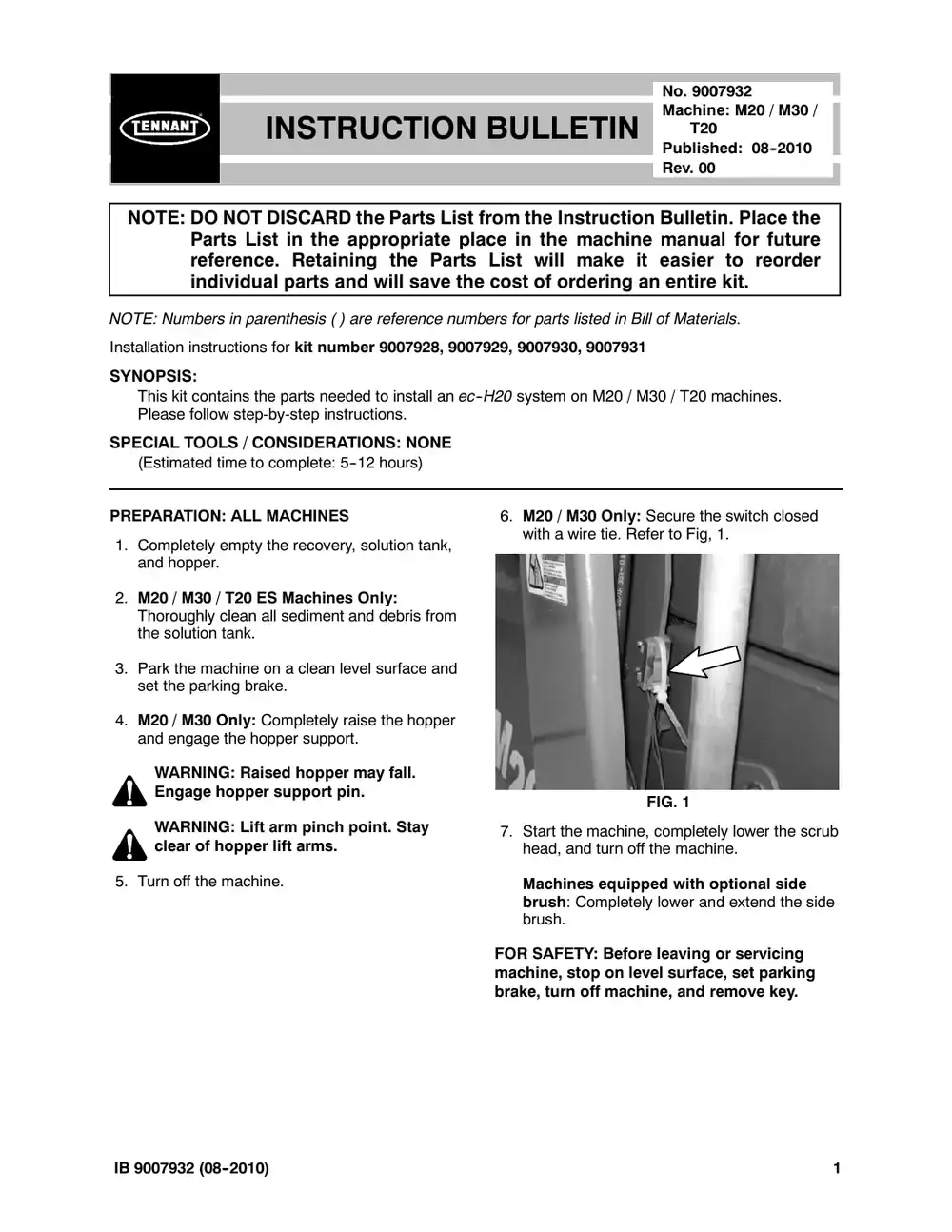
Tennant M20 instruction bulletin 9007932, page 1 of 72
Page 1 of 72 SES ref PF-FXMU-45TD‌‌​⁠‍‍‌​‌​‍‌⁠‌⁠​⁠‌‌⁠⁠‍⁠​‌⁠‌​​​​‌​‍‌​​‌‌​‍‍​‍‍⁠⁠‌⁠‍‍‌‍​‌‌‍‌​‍
Text of this page
INSTRUCTION NOTE: DO NOT DISCARD the Parts List Parts List in the appropriate pla reference. Retaining the Parts individual parts and will save the NOTE: Numbers in parenthesis ( ) are reference num Installation instructions for kit number TN4012490, 9007 SYNOPSIS: This kit contains the parts needed to install an ec- Please follow step-by-step instructions. SPECIAL TOOLS / CONSIDERATIONS: NONE (Estimated time to complete: 5--12 hours) PREPARATION: ALL MACHINES 1. Completely empty the recovery, solution tank, and hopper. 2. M20 / M30 / T20 ES Machines Only: Thoroughly clean all sediment and debris from the solution tank. 3. Park the machine on a clean level surface and set the parking brake. 4. M20 / M30 Only: Completely raise the hopper and engage the hopper support. WARNING: Raised hopper may fall. Engage hopper support pin. WARNING: Lift arm pinch point. Stay clear of hopper lift arms. 5. Turn off the machine. IB 9007932 (08--2010) No. 9007932 Machine: M20 / M30 / N BULLETIN T20 Published: 08--2010 Rev. 00 from the Instruction Bulletin. Place the ace in the machine manual for future s List will make it easier to reorder e cost of ordering an entire kit. mbers for parts listed in Bill of Materials. 7929, TN4012492, TN4012493 --H20 system on M20 / M30 / T20 machines. 6. M20 / M30 Only: Secure the switch closed with a wire tie. Refer to Fig, 1. FIG. 1 7. Start the machine, completely lower the scrub head, and turn off the machine. Machines equipped with optional side brush: Completely lower and extend the side brush. FOR SAFETY: Before leaving or servicing machine, stop on level surface, set parking brake, turn off machine, and remove key. 1
Tennant M20 instruction bulletin 9007932, page 2 of 72
Page 2 of 72
Text of this page
8. Disconnect the battery cables from the battery and remove the battery from the machine. Set the battery aside. WARNING: Always disconnect battery cables from machine before working on electrical components. 9. Remove the operator seat / seat plate from the machine. Set the seat / seat plate aside. 10.Remove the engine shroud, front shroud, and seat shroud from the machine. Set the removed shrouds aside. 11. Remove the lower cover from the machine. Set the lower cover and hardware aside. Refer to Fig. 2. FIG. 2 12. LP powered machines only: Remove the LP tank from the machine. Refer to the Operators Manual for instructions how to remove the LP tank. Set the LP tank aside. 13. Machines with Overhead Guard Option Only: Remove the hardware holding the back end of the overhead guard to the machine. Set the hardware aside. NOTE: Machines equipped with overhead guards only: It may be necessary to prop the back end of the overhead guard up to remove the mounting bracket. 2 14. Machines not equipped with optional spray hose: Remove the 2.5” plug from the mounting bracket located in the corner of the operators compartment. Discard the plug. Refer to Fig. 3. Mounting bracket 2.5” plug FIG. 3 15. Machines with Spray Hose Option Only: Disconnect spray hose fittings / hoses from the machine. Set removed items aside since they will need to be reinstalled after the mounting bracket is reinstalled onto the machine. Refer to Fig. 3. 16. Remove the mounting bracket from the machine. Set the mounting bracket and hardware aside. Refer to Fig. 3. 17. Remove the access panel from the operator compartment. Set the access panel and hardware aside. Refer to Fig. 4. FIG. 4 IB 9007932 (08--2010)
Tennant M20 instruction bulletin 9007932, page 3 of 72
Page 3 of 72
Text of this page
18. Machines with Side Brush Option Only: Remove the side brush guard assembly from the machine. Set the side brush guard assembly and all hardware aside. Refer to Fig. 5. FIG. 5 19. Raise and lock the recovery tank cover open. IB 9007932 (08--2010) 3
Tennant M20 instruction bulletin 9007932, page 4 of 72
Page 4 of 72
Text of this page
INSTALLATION: M20 / M30 / T20 (CYLINDRICAL HEADS ONLY) ES MACHINES 1. Disconnect the main wire harness and all hoses from the ES pump assembly and pressure switch inside the recovery tank. Refer to Fig. 1. Remove ES pump assembly assembly, hardware, and ho recovery tank FIG 3. Install the cap assembly onto the recovery tank. Refer to Fig. 2. Cap assembly FIG. 2 4 2. Remove the ES pump assembly, strainer assembly, and interconnected hoses from the recovery tank. Discard the removed ES components. Refer to Fig. 1. y, strainer oses from Leave pressure switchinstalledin recovery tank Disconnect main harness from ES pressure switch G. 1 4. Remove the plastic fitting from the recovery tank. Refer to Fig. 3. Remove and discard plastic fitting and clamp. Replace with plug FIG. 3 IB 9007932 (08--2010)
Tennant M20 instruction bulletin 9007932, page 5 of 72
Page 5 of 72
Text of this page
5. Remove the auto fill assembly from the machine. Refer to Fig. 4. 6. Disconnect the main wire harness from the auto fill solenoids. Do not disconnect the float switch connector. Refer to Fig. 4. 7. Disconnect the auto fill hose from the solenoid and remove the hose from the machine. Discard the hose. Refer to Fig. 4. 8. Remove the auto--fill solenoids and fittings from the machine. Discard the fittings and solenoids. Refer to Fig. 4. Disconnect auto--fill hose from solenoid and remove from solenoid and remove hose from machine Remove ES auto--fill assembly from machine FIG IB 9007932 (08--2010) Disconnect main wire harness from ES auto--fill solenoids and remove solenoids and fittings from machine G. 4 5
Tennant M20 instruction bulletin 9007932, page 6 of 72
Page 6 of 72
Text of this page
Machines with later ES system configuration Solution tank Remove 48” hose / fitting / clamp. Install 1/2” elbow fitting into t--fitting Leave fitting / hose routed to scrub head installed Machines with older ES system configuration Rem fitting Remove hose / fittings / clamp Install 1/2” elbow fitting into t--fitting Leave fitting / hose routed to scrub head installed FIG 9. Disconnect ES system hoses / fittings from the solution tank and ES pump. Discard removed hoses / fittings. Refer to Fig. 5. NOTE: Leave the 90°fitting and hose routed to the scrub head installed on the machine. 10. Cut all remaining hoses from the ES pump and remove the hoses from the machine. Discard the removed hoses. Refer to Fig. 5. 11. Cut a 48” length of PVC hose. 12. Install a 1/2” elbow fitting onto the t--fitting located on the bottom of the solution tank. Refer to Fig. 5. 13. Use a hose clamp to connect the 48” PVC hose to the new elbow fitting installed in the previous step. Refer to Fig. 5. 6 Install plug into hole in solution tank Disconnect main wire Remove hose / harness from fitting / clamp ES pump move / clamp Solution tank Remove hose G. 5 14. Route the 48” PVC hose from the bottom of the solution tank and up into the operator compartment. Refer to Fig. 6. FIG. 6 IB 9007932 (08--2010)
Tennant M20 instruction bulletin 9007932, page 7 of 72
Page 7 of 72
Text of this page
Solution tank Reinstallmountingbracket if machine is equipped with optional spray hose. Discard bracket if machine is not equipped with optional spray hose equipped with optional spray hose Remove and discard ES tank Use hardware to reinstall mounting bracket if machine is equipped with optional spray hose. Discard hardware if not reinstalling mounting bracket Remove and discard ES hose and fittings FIG 15. Disconnect the main wire harness from the detergent pump. Refer to Fig. 7. 16. Remove the ES hose and fittings from the operators compartment and the ES tank from behind the operator seat. Reinstall the mounting bracket if the machine is equipped with the optional spray hose. Discard the ES tank, hose, and fittings. Refer to Fig. 7. 17. Place a chock behind each rear tire, jack up the front end of the machine, place jack stands under the front of the machine, and lower the machine onto the jack stands. FOR SAFETY: When servicing machine, block machine tires before jacking machine up. Use a hoist or jack that will support the weight of the machine. Jack machine up at designated locations only. Support machine with jack stands. 18. Cut a 20” length of 0.38 ID PVC hose and a 60” length of 0.50 ID PVC hose. IB 9007932 (08--2010) Discard hardware G. 7 19. Use a hose clamp to install the 20” PVC hose and 60” PVC hose onto a y--fitting. 20. Route the PVC hose (end with the y--fitting--if machine is equipped with optional side brush) from the operator compartment, down along the frame center beam, and to the scrub head. Refer to Fig. 8. FIG. 8 21. Label the end of the 60” length of 0.50 ID PVC hose still in the operator compartment “SCRUB HEAD”. 7
Tennant M20 instruction bulletin 9007932, page 8 of 72
Page 8 of 72
Text of this page
NOTE: Complete Step 22 through Step 38 only if machine is equipped with the optional side brush. 22. Cut three 2” lengths of 0.50 ID PVC hose. 23. Cut a 13” length of 0.38” ID PVC hose. 24. Assemble the check valve, straight fittings, 13” hose, and 2” hoses as shown in Fig. 9. Note the direction of flow. 25. Use a hose clamp to attach the hose assembly assembled in the previous step to the y--fitting connected to the 60” 0.50 ID PVC hose. Refer to Fig. 9. 26. Use two M5 pan screws, two flat washers, and two M5 hex nuts to install the solenoid onto the solenoid bracket. Refer to Fig. 9. 27. Use a M8 thread roller to install the solenoid / solenoid bracket onto the frame of the machine. Refer to Fig. 9. From y--fitting from solution tan Check 2” 0.50” valve ID PVC hose Straight fitting 13” 0.38” ID PVC hose Direction of flow Straightfitting Check valve M8 thread roller Solenoid FIG 8 28. Trim 2” inches from the shorter end and 6” from the longer end of the bent hose. 29. Cut the bent hose 12” from the longer end of the hose. Refer to Fig. 9. 30. Use two hose clamps to install a check valve between the two sections of hose cut in the previous step. Note the direction of flow. Refer to Fig. 9. 31. Use a hose clamp to connect the trimmed hose to the solenoid. Refer to Fig. 9. 32. Use a hose clamp to connect the other end of the trimmed hose to the y--fitting connected to the 60” PVC hose from the operator compartment. Refer to Fig. 9. 33. Use a hose clamp to connect a 26” PVC hose to the solenoid. Refer to Fig. 9. 60” hose from operator compartment nk 2” 0.50” ID Use cable tie to PVC hose secure 60” hose assembly to frame T--fitting of machine 12” Hose Direction of flow 26” PVC hose to side brush G. 9 IB 9007932 (08--2010)
Tennant M20 instruction bulletin 9007932, page 9 of 72
Page 9 of 72
Text of this page
34. Cut the solution supply hose 2.5” from where the hose is connected to the dispensing tube. Refer to Fig. 10. 35. Use a hose clamp to connect the y--fitting to the 2.5” solution supply hose. Refer to Fig. 10. 36. Use a hose clamp to connect the hose from the solution supply solenoid to the y--fitting. Refer to Fig. 10. From e supply so Cut side brush supply hose 2.5” from dispensing tube Dispensing tube FIG IB 9007932 (08--2010) 37. Use a hose clamp to connect the PVC hose from the solenoid to the y--fitting. Refer to Fig. 10. 38. Reinstall the side brush guard onto the machine. From solution supply solenoid ec--H20 olenoid Y--fitting 2.5” solution supply hose G. 10 9
Tennant M20 instruction bulletin 9007932, page 10 of 72
Page 10 of 72
Text of this page
39. Remove the skirt assembly from the front of the scrub head. Set the skirt assembly and mounting hardware aside. Refer to Fig. 11. Front of scrub head Set skirt assembly and hardware aside FIG. 11 From ec--H20 supply Front of scrub head Solution spray bar manifold FIG 10 40. Cut the solution supply hose to the scrub head approximately 2” from the top of the skirt. Refer to Fig. 12. 41. Use a hose clamp to connect the t--fitting to the hose from the solution spray bar manifold. Refer to Fig. 12. 42. Use a hose clamp to connect the hose from the scrub head solution solenoid to the t--fitting. Refer to Fig. 12. 43. Use a hose clamp to connect the hose from the y--fitting to the t--fitting. Refer to Fig. 12. 44. Use a cable tie to secure the hose assembly from the previous step to the center beam of the frame of the machine. Refer to Fig. 12. 45. Reinstall the skirt assembly onto the front of the scrub head. Refer to Fig. 12. From scrub head solution control solenoid Cut scrub head solution supply hose 2” above skirt Skirt G. 12 IB 9007932 (08--2010)
Tennant M20 instruction bulletin 9007932, page 11 of 72
Page 11 of 72
Text of this page
FIG 46. Drill a 11/32” (0.344) hole through the instrument panel assembly. Refer to Fig. 13. 47. Remove the instrument panel label from the instrument panel. 48. Use a brake cleaning solvent to clean remaining residue from the instrument panel. 49. Install the new instrument panel label onto the instrument panel. 50. Insert the LED light into the hole drilled into the 11/32” (0.344”) hole. Refer to Fig. 13. 51. Begin routing the ec--H20 harness at the upper corner of the engine compartment. Loosely cable tie the ec--H20 harness to the main wire harness. 52. Route the ec--H20 harness along the main harness and down to the FaST connector on the the main harness and connect the ec--H20 harness to the FaST connector. IB 9007932 (08--2010) G. 13 53. Route ec--H20 harness ec--H20 assembly leads into the the operator compartment. Refer to Fig. 14. FIG. 14 54. Route the ec--H20 harness along the bottom of the main wire harness and to the front of the machine. Refer to Fig. 15. FIG. 15 11
Tennant M20 instruction bulletin 9007932, page 12 of 72
Page 12 of 72
Text of this page
55. Route the ec--H20 harness ground lead to the engine ground and connect the ground lead to the engine ground. Refer to Fig. 16. 56. Route the remainder of the ec--H20 harness along the main wire harness and into the battery compartment. 57. Cut the cable ties from the rubber boot and slide the boot from the ignition switch. 58. Remove the ignition switch from the dash panel. Set the ignition switch mounting hardware aside. 59. Slide the ec--H20 harness ignition switch lead through the bottom of the boot and connect the ignition lead to the ignition switch PIN 30 terminal. Refer to Fig. 16. FIG 12 60. Reinstall the ignition switch onto the dash panel. 61. Reinstall the rubber boot onto the ignition switch and use two cable tires to secure the boot onto the switch. 62. Connect the ec--H20 harness to the LED light. Refer to Fig. 16. 63. Use several cable ties to secure the ec--H20 harness to the main wire harness behind the control panel. G. 16 IB 9007932 (08--2010)
Tennant M20 instruction bulletin 9007932, page 13 of 72
Page 13 of 72
Text of this page
64. Remove the cover from the ec--H20 assembly. Set the cover and mounting hardware aside. 65. Use two hex screws and two flat washers to install the ec--H20 assembly behind the operator seat.. 66. Cut approximately 1” from the mounting bracket. Refer to Fig. 17. FIG. 17 67. Slide the grommet onto the hoses /cables on the ec--H20 assembly. Refer to Fig. 21. 68. Connect the 60” PVC hose to the ec--H20 assembly. 12” 0.50” ID PVC hose 30” 0.25” ID PVC hose (Qty 2) Install storage bag onto back of operator seat FIG IB 9007932 (08--2010) 69. Connect the 48” PVC hose to the ec--H20 assembly. 70. Connect the ec--H20 harness to the ec--H20 assembly. Refer to Fig. 16. 71. Install the grommet into the mounting bracket. Refer to Fig. 18. 72. Reinstall the mounting bracket into the operator compartment. 73. Reinstall the cover onto the ec--H20 assembly. 74. Place the battery back into the battery compartment and reconnect the battery cables to the battery. 75. Install the storage bag onto the back of the operator seat. Refer to Fig. 18. 76. Assemble the ec--H2O flush hose assemblies. Refer to Fig. 18. 77. Reinstall all covers and components removed from the machine to install the ec--H20 kit. 78. Remove the cable tie holding the switch closed. 79. Reconnect the battery cables to the battery. Mounting bracket Grommet To ec--H20 assembly From scrub head G. 18 13
Tennant M20 instruction bulletin 9007932, page 14 of 72
Page 14 of 72
Text of this page
INSTALLATION: M20 / M30 / T20 (CYLINDRICAL HEADS ONLY) STANDARD MACHINES 1. Place a chock behind each rear tire, jack up the front end of the machine, place jack stands under the front of the machine, and lower the front of the machine down onto the jack stands. FOR SAFETY: When servicing machine, block machine tires before jacking machine up. Use a hoist or jack that will support the weight of the machine. Jack machine up at designated locations only. Support machine with jack stands. 2. Disconnect the 96” PVC hose from the solution tank. Discard the hose clamp. Refer to Fig. 1. 3. Remove the straight fitting from the 90° fitting on the bottom of the solution tank. Discard the straight fitting. Refer to Fig. 1. Solution tank Remove fitting / clamp Disconnect hose from solution tank Solution tank Elbow fittin (90_BM12/PM12 60” PVC hose (X) to operator compartment T FIG 14 4. Install a straight fitting and two two 90° fittings into the t--fitting. Refer to Fig. 1. 5. Install the t--fitting from the previous step onto the 90° fitting on the bottom of the solution tank. Refer to Fig. 1. 6. Use a hose clamp to connect the 96” PVC hose to the t--fitting assembly. Refer to Fig. 1. 7. Cut a 48” length of PVC hose. Refer to Fig. 1. 8. Use a hose clamp to connect the 60” PVC hose to the new elbow fitting installed on the t--fitting. Refer to Fig. 1. n k Straight ng fitting 2) Elbow fitting T--fitting (90_ BM 08/ PM12) 96” PVC hose to scrub head G. 1 IB 9007932 (08--2010)
Tennant M20 instruction bulletin 9007932, page 15 of 72
Page 15 of 72
Text of this page
9. Route the 48” PVC hose from the bottom of the solution tank and up into the operator compartment. Refer to Fig. 2. FIG. 2 10. Cut a 20” length of PVC hose and a 60” length of PVC hose. 11. Use a hose clamp to install the 20” PVC hose and 60” PVC hose onto a y--fitting. Refer to Fig. 3. 12. Route the end of the PVC hose (end with the y--fitting--if machine is equipped with optional side brush) from the operator compartment down to the scrub head. Refer to Fig. 3. FIG. 3 13. Label the end of the 60” length of 0.50 ID PVC hose still in the operator compartment “SCRUB HEAD”. IB 9007932 (08--2010) 15
Tennant M20 instruction bulletin 9007932, page 16 of 72
Page 16 of 72
Text of this page
NOTE: Complete Step 14 through Step 30 only if machine is equipped with the optional side brush. 14. Cut three 2” lengths of 0.50 ID PVC hose. 15. Cut a 13” length of 0.38” ID PVC hose. 16. Assemble the check valve, straight fittings, 13” hose, and 2” hoses as shown in Fig. 4. Note direction of flow. 17. Use a hose clamp to attach the hose assembly assembled in the previous step to the y--fitting connected to the 60” 0.50 ID PVC hose. Refer to Fig. 4. 18. Use two M5 pan screws, two flat washers, and two M5 hex nuts to install the solenoid onto the solenoid bracket. Refer to Fig. 4. 19. Use a M8 thread roller to install the solenoid / solenoid bracket onto the frame of the machine. Refer to Fig. 4. From y--fitting from solution tan Check 2” 0.50” valve ID PVC hose Straight fitting 13” 0.38” ID PVC hose Direction of flow Straightfitting Check valve M8 thread roller Solenoid FIG 16 20. Trim 2” inches from the shorter end and 6” from the longer end of the bent hose. 21. Cut the bent hose 12” from the longer end of the hose. Refer to Fig. 4. 22. Use two hose clamps to install a check valve between the two sections of hose cut in the previous step. Note the direction of flow. Refer to Fig. 4. 23. Use a hose clamp to connect the trimmed hose to the solenoid. Refer to Fig. 4. 24. Use a hose clamp to connect the other end of the trimmed hose to the y--fitting connected to the 60” PVC hose from the operator compartment. Refer to Fig. 4. 25. Use a hose clamp to connect a 26” PVC hose to the solenoid. Refer to Fig. 4. 60” hose from operator compartment nk 2” 0.50” ID Use cable tie to PVC hose secure 60” hose assembly to frame T--fitting of machine 12” Hose Direction of flow 26” PVC hose to side brush G. 4 IB 9007932 (08--2010)
Tennant M20 instruction bulletin 9007932, page 17 of 72
Page 17 of 72
Text of this page
26. Cut the solution supply hose 2.5” from where the hose is connected to the dispensing tube. Refer to Fig. 5. 27. Use a hose clamp to connect the y--fitting to the 2.5” solution supply hose. Refer to Fig. 5. 28. Use a hose clamp to connect the hose from the solution supply solenoid to the y--fitting. Refer to Fig. 5. From ec supply so Cut side brush supply hose 2.5” from dispensing tube Dispensing tube FIG IB 9007932 (08--2010) 29. Use a hose clamp to connect the 20” PVC hose from the solenoid to the y--fitting. Refer to Fig. 5. 30. Reinstall the side brush guard onto the machine. From solution c--H20 supply solenoid olenoid Y--fitting 2.5” solution supply hose G. 5 17
Tennant M20 instruction bulletin 9007932, page 18 of 72
Page 18 of 72
Text of this page
31. Remove the skirt assembly from the front of the scrub head. Set the skirt assembly and mounting hardware aside. Refer to Fig. 6. Front of scrub head Set skirt assembly and hardware aside FIG. 6 From ec--H20 supply Front of scrub head Solution spray bar manifold FIG 18 32. Cut the solution supply hose to the scrub head approximately 2” from the top of the skirt. Refer to Fig. 7. 33. Use a hose clamp to connect the t--fitting to the hose from the solution spray bar manifold. Refer to Fig. 7. 34. Use a hose clamp to connect the hose from the scrub head solution solenoid to the t--fitting. Refer to Fig. 7. 35. Use a hose clamp to connect the 20” PVC hose from the y--fitting to the t--fitting. Refer to Fig. 7. 36. Reinstall the skirt assembly onto the front of the scrub head. Refer to Fig. 6. From scrub head solution control solenoid T--fitting Cut scrub head solution supply hose 2” above skirt Skirt G. 7 IB 9007932 (08--2010)
Tennant M20 instruction bulletin 9007932, page 19 of 72
Page 19 of 72
Text of this page
FIG 37. Drill a 11/32” (0.344”) hole through the instrument panel assembly. Refer to Fig. 8. 38. Remove the instrument panel label from the instrument panel. 39. Use a brake cleaning solvent to clean remaining residue from the instrument panel. 40. Install the new instrument panel label onto the instrument panel. 41. Insert the ec--H20 warning light into the 11/32” (0.344”) hole. Refer to Fig. 8. 42. Begin routing the ec--H20 harness at the upper corner of the engine compartment. Loosely cable tie the ec--H20 harness to the main wire harness. 43. Route the ec--H20 harness along the main harness and down to the FaST connector on the the main harness and connect the ec--H20 harness to the FaST connector. IB 9007932 (08--2010) G. 8 44. Route ec--H20 harness ec--H20 assembly leads into the the operator compartment. Refer to Fig. 9. FIG. 9 45. Route the ec--H20 harness along the bottom of the main wire harness and to the front of the machine. Refer to Fig. 10. FIG. 10 19
Tennant M20 instruction bulletin 9007932, page 20 of 72
Page 20 of 72
Text of this page
46. Route the ec--H20 harness ground lead to the engine ground and connect the ground lead to the engine ground. Refer to Fig. 11. 47. Route the ec--H20 harness along the main wire harness and into the battery compartment. 48. Cut the cable ties from the rubber boot and slide the boot off from the ignition switch. 49. Slide the ec--H20 harness ignition switch lead through the bottom of the boot and connect the ignition lead to the PIN 30 terminal on the ignition switch. Refer to Fig. 11. FIG 20 50. Reinstall the rubber boot onto the ignition switch. 51. Connect the ec--H20 harness to the LED light. Refer to Fig. 11. 52. Use several cable ties to secure the ec--H20 harness behind the control panel.. G. 11 IB 9007932 (08--2010)
Tennant M20 instruction bulletin 9007932, page 21 of 72
Page 21 of 72
Text of this page
53. Remove the cover from the ec--H20 assembly. Set the cover and mounting hardware aside. 54. Use two hex screws and two flat washers to install the ec--H20 assembly behind the operator seat. 55. Cut approximately 1” from the mounting bracket. Refer to Fig. 12. FIG. 12 56. Slide the grommet onto the hoses /cables on the ec--H20 assembly. Refer to Fig. 15. 57. Connect the 60” PVC hose to the ec--H20 assembly. 12” 0.50” ID PVC hose 30” 0.25” ID PVC hose (Qty 2) Install storage bag onto back of operator seat FIG IB 9007932 (08--2010) 58. Connect the 48” PVC hose to the ec--H20 assembly. 59. Connect the ec--H20 harness to the ec--H20 assembly. Refer to Fig. 11. 60. Install the grommet into the mounting bracket. Refer to Fig. 13. 61. Reinstall the mounting bracket into the operator compartment. Refer to Fig. 13. 62. Reinstall the cover onto the ec--H20 assembly. 63. Place the battery back into the battery compartment and reconnect the battery cables to the battery. 64. Install the storage bag onto the back of the operator seat. Refer to Fig. 13. 65. Assemble the ec--H2O flush hose assemblies. Refer to Fig. 13. 66. Reinstall all covers and components removed from the machine to install the ec--H20 kit. 67. Remove the cable tie holding the switch closed. 68. Reconnect the battery cables to the battery. Mounting bracket Grommet To ec--H20 assembly From scrub head G. 13 21
Tennant M20 instruction bulletin 9007932, page 22 of 72
Page 22 of 72
Text of this page
INSTALLATION: FaST GEN I MACHINES -- M20 / T20 (CYLINDRICAL HEADS) -- ONLY 1. Disconnect the hoses and wire harness from the FaST assembly and remove the entire FaST assembly from the machine. Discard the FaST assembly and removed hardware. Refer to Fig. 1. Remove and discard hoses and clamps FIG 22 2. Remove the hoses and components labeled in Fig. 1 and discard the hoses and hose clamps. Remove and discard hose and clamps Remove FaST foam filter assembly Remove and discard hose and clamps G. 1 IB 9007932 (08--2010)
Tennant M20 instruction bulletin 9007932, page 23 of 72
Page 23 of 72
Text of this page
NOTE: Complete Step 3 through Step 12 only if machine is equipped with the optional side brush. 3. Place a chock behind each rear tire, jack up the front end of the machine, place jack stands under the front of the machine, and lower the machine onto the jack stands. FOR SAFETY: When servicing machine, block machine tires before jacking machine up. Use a hoist or jack that will support the weight of the machine. Jack machine up at designated locations only. Support machine with jack stands. 4. Cut a 60” length and three 2” lengths of 0.50 ID PVC hose. 5. Cut a 13” length of 0.38” ID PVC hose. 6. Assemble the check valve, straight fittings, 13” hose, and 2” hoses as shown in Fig. 2. Note the direction of flow. From y--fitting from solution tan Check 2” 0.50” valve ID PVC hose Straight fitting 13” 0.38” ID PVC hose Direction of flow Straightfitting Check valve Solenoid FIG IB 9007932 (08--2010) 7. Trim 2” inches from the shorter end and 6” from the longer end of the bent hose. 8. Cut the bent hose 12” from the longer end of the hose. Refer to Fig. 2. 9. Use two hose clamps to install a check valve between the two sections of hose cut in the previous step. Note the direction of flow. Refer to Fig. 2. 10. Use a hose clamp to connect the trimmed hose to the solenoid. Refer to Fig. 2. 11. Use a hose clamp to connect the other end of the trimmed hose to the y--fitting connected to the 60” PVC hose from the operator compartment. Refer to Fig. 2. 12. Use a hose clamp to connect a 26” PVC hose to the solenoid. Refer to Fig. 2. 60” hose from operator compartment nk 2” 0.50” ID Use cable tie to PVC hose secure 60” hose assembly to frame T--fitting of machine 12” Hose Direction of flow 26” PVC hose to side brush G. 2 23
Tennant M20 instruction bulletin 9007932, page 24 of 72
Page 24 of 72
Text of this page
FIG 13. Carefully drill a 11/32” (0.344”) hole through the instrument panel assembly. Refer to Fig. 3. 14. Remove the instrument panel label from the instrument panel. 15. Use a brake cleaning solvent to clean remaining residue from the instrument panel. 16. Install the new instrument panel label onto the instrument panel. 17. Reinstall the instrument panel into the dash panel. 18. Insert the ec--H20 warning light into the 11/32” (0.344”) hole. Refer to Fig. 3. 19. Begin routing the ec--H20 harness at the upper corner of the engine compartment. Loosely cable tie the ec--H20 harness to the main wire harness. 20. Route the ec--H20 harness along the main harness and down to the FaST connector on the the main harness and connect the ec--H20 harness to the FaST connector. 24 G. 3 21. Route ec--H20 harness ec--H20 assembly leads into the the operator compartment. Refer to Fig. 4. FIG. 4 22. Route the ec--H20 harness along the bottom of the main wire harness and to the front of the machine. Refer to Fig. 5. FIG. 5 IB 9007932 (08--2010)
Tennant M20 instruction bulletin 9007932, page 25 of 72
Page 25 of 72
Text of this page
23. Route the ec--H20 harness ground lead to the engine ground and connect the ground lead to the engine ground. Refer to Fig. 6. 24. Route the ec--H20 harness along the main wire harness and into the battery compartment. 25. Cut the cable ties from the rubber boot and slide the boot off from the ignition switch. 26. Slide the ec--H20 harness ignition switch lead through the bottom of the boot and connect the ignition lead to PIN 30 on the ignition switch. Refer to Fig. 6. FIG IB 9007932 (08--2010) 27. Reinstall the rubber boot onto the ignition switch. 28. Connect the ec--H20 harness to the LED light. Refer to Fig. 6. 29. Use several cable ties to secure the ec--H20 harness to the main wire harness behind where the battery is located. G. 6 25
Tennant M20 instruction bulletin 9007932, page 26 of 72
Page 26 of 72
Text of this page
30. Remove the cover from the ec--H20 assembly. Set the cover and mounting hardware aside. 31. Use two hex screws and two flat washers to install the ec--H20 assembly behind the operator seat. 32. Cut approximately 1” from the mounting bracket. Refer to Fig. 7. FIG. 7 33. Slide the grommet onto the hoses /cables on the ec--H20 assembly. Refer to Fig. 8. 34. Connect the 60” PVC hose to the ec--H20 assembly. 12” 0.50” ID PVC hose 30” 0.25” ID PVC hose (Qty 2) Install storage bag onto back of operator seat FIG 26 35. Connect the 48” PVC hose to the ec--H20 assembly. 36. Connect the ec--H20 harness to the ec--H20 assembly. Refer to Fig. 6. 37. Install the grommet into the mounting bracket. Refer to Fig. 8. 38. Reinstall the mounting bracket into the operator compartment. 39. Reinstall the cover onto the ec--H20 assembly. 40. Place the battery back into the battery compartment and reconnect the battery cables to the battery. 41. Install the storage bag onto the back of the operator seat. Refer to Fig. 10. 42. Assemble the ec--H2O flush hose assemblies. Refer to Fig. 10. 43. Reinstall all covers and components removed from the machine to install the ec--H20 kit. 44. Remove the cable tie holding the switch closed. 45. Reconnect the battery cables to the battery. Mounting bracket Grommet To ec--H20 assembly From scrub head G. 8 IB 9007932 (08--2010)
Tennant M20 instruction bulletin 9007932, page 27 of 72
Page 27 of 72
Text of this page
INSTALLATION: M20 / M30 / T20 (CYLINDRICAL HEADS ONLY) FaST GEN II MACHINES 1. Disconnect the hoses and wire harness from the FaST assembly and remove the entire FaST assembly from the machine. Discard the FaST assembly and removed hardware. Refer to Fig. 1. Remove and discard hoses FIG IB 9007932 (08--2010) 2. Remove the hoses labeled in Fig. 1 and discard the hoses and hose clamps. G. 1 27
Tennant M20 instruction bulletin 9007932, page 28 of 72
Page 28 of 72
Text of this page
NOTE: Complete Step 3 through Step 12 only if machine is equipped with the optional side brush. 3. Place a chock behind each rear tire, jack up the front end of the machine, place jack stands under the front of the machine, and lower the machine onto the jack stands. FOR SAFETY: When servicing machine, block machine tires before jacking machine up. Use a hoist or jack that will support the weight of the machine. Jack machine up at designated locations only. Support machine with jack stands. 4. Cut a 60” length and three 2” lengths of 0.50 ID PVC hose. 5. Cut a 13” length of 0.38” ID PVC hose. 6. Assemble the check valve, straight fittings, and 13” hose / 2” hoses as shown in Fig. 2. Note the direction of flow. From y--fitting from solution tan Check 2” 0.50” valve ID PVC hose Straight fitting 13” 0.38” ID PVC hose Direction of flow Straightfitting Check valve Solenoid FIG 28 7. Trim 2” inches from the short end and 6” from the long end of the bent hose. 8. Cut the bent hose 12” from the longer end of the hose. Refer to Fig. 2. 9. Use two hose clamps to install a check valve between the two sections of hose cut in the previous step. Note the direction of flow. Refer to Fig. 2. 10. Use a hose clamp to connect the trimmed hose to the solenoid. Refer to Fig. 2. 11. Use a hose clamp to connect the other end of the trimmed hose to the y--fitting connected to the 60” PVC hose from the operator compartment. Refer to Fig. 2. 12. Use a hose clamp to connect a 26” PVC hose to the solenoid. Refer to Fig. 2. 60” hose from operator compartment nk 2” 0.50” ID Use cable tie to PVC hose secure 60” hose assembly to frame T--fitting of machine 12” Hose Direction of flow 26” PVC hose to side brush G. 2 IB 9007932 (08--2010)
Tennant M20 instruction bulletin 9007932, page 29 of 72
Page 29 of 72
Text of this page
FIG 13. Drill a 11/32” (0.344”) hole through the instrument panel assembly. Refer to Fig. 3. 14. Remove the instrument panel label from the instrument panel. 15. Use a brake cleaning solvent to clean remaining residue from the instrument panel. 16. Install the new instrument panel label onto the instrument panel. 17. Reinstall the instrument panel into the dash panel. 18. Insert the ec--H20 warning light into the hole drilled in the previous step. Refer to Fig. 3. 19. Begin routing the ec--H20 harness at the upper corner of the engine compartment. Loosely cable tie the ec--H20 harness to the main wire harness. 20. Route the ec--H20 harness along the main harness and down to the FaST connector on the the main harness and connect the ec--H20 harness to the FaST connector. IB 9007932 (08--2010) G. 3 21. Route ec--H20 harness ec--H20 assembly leads into the the operator compartment. Refer to Fig. 4. FIG. 4 22. Route the ec--H20 harness along the bottom of the main wire harness and to the front of the machine. Refer to Fig. 5. FIG. 5 29
Tennant M20 instruction bulletin 9007932, page 30 of 72
Page 30 of 72
Text of this page
23. Route the ec--H20 harness ground lead to the engine ground and connect the ground lead to the engine ground. Refer to Fig. 6. 24. Route the ec--H20 harness along the main wire harness and into the battery compartment. 25. Cut the cable ties from the rubber boot and slide the boot off from the ignition switch. 26. Slide the ec--H20 harness ignition switch lead through the bottom of the boot and connect the ignition lead to the PIN 39 terminal on the ignition switch. Refer to Fig. 6. FIG 30 27. Reinstall the rubber boot onto the ignition switch. 28. Connect the ec--H20 harness to the LED light. Refer to Fig. 6. 29. Use several cable ties to secure the ec--H20 harness to the main wire harness behind where the battery is located. G. 6 IB 9007932 (08--2010)
Tennant M20 instruction bulletin 9007932, page 31 of 72
Page 31 of 72
Text of this page
30. Remove the cover from the ec--H20 assembly. Set the cover and mounting hardware aside. 31. Use two hex screws and two flat washers to install the ec--H20 assembly behind the operator seat. 32. Cut approximately 1” from the mounting bracket. Refer to Fig. 7. FIG. 7 33. Slide the grommet onto the hoses /cables on the ec--H20 assembly. Refer to Fig. 8. 34. Connect the 60” PVC hose to the ec--H20 assembly. 12” 0.50” ID PVC hose 30” 0.25” ID PVC hose (Qty 2) Install storage bag onto back of operator seat FIG IB 9007932 (08--2010) 35. Connect the 48” PVC hose to the ec--H20 assembly. 36. Connect the ec--H20 harness to the ec--H20 assembly. Refer to Fig. 6. 37. Install the grommet into the mounting bracket. Refer to Fig. 8. 38. Reinstall the mounting bracket into the operator compartment. 39. Reinstall the cover onto the ec--H20 assembly. 40. Place the battery back into the battery compartment and reconnect the battery cables to the battery. 41. Install the storage bag onto the back of the operator seat. Refer to Fig. 8. 42. Assemble the ec--H2O flush hose assemblies. Refer to Fig. 8. 43. Reinstall all covers and components removed from the machine to install the ec--H20 kit. 44. Remove the cable tie holding the switch closed. 45. Reconnect the battery cables to the battery. Mounting bracket Grommet To ec--H20 assembly From scrub head G. 8 31
Tennant M20 instruction bulletin 9007932, page 32 of 72
Page 32 of 72
Text of this page
INSTALLATION: T20 STANDARD (DISK HEADS ONLY) Leave plast head fitting in solution t Remove and discard 90_ p fittings and h clamp Leave connected to water solenoid valve Water solenoid valve Remove discar rubber c FIG 1. Remove the rubber cap from the solution control manifold. Discard the cap and hose clamp. Refer to Fig. 1. 2. Disconnect the hose from the 90° fitting on the bottom of the solution tank. Discard the hose clamp. Refer to Fig. 1. 3. Remove the 90° fitting from the plastic bulk head fitting on the bottom of the solution tank. Refer to Fig. 1. 32 tic bulk installed tank plastic hose Solution tank Elbow fitting (90_ BM 08/ PM12) Straight fitting T--fitting Elbow fitting (90_ BM12/PM12) and rd cap G. 1 4. Install two 90° fittings and a straight fitting into the t--fitting. Refer to Fig. 1. 5. Install the t--fitting from the previous step into the plastic bulk head fitting on the bottom of the solution tank. Refer to Fig. 1 and Fig. 2. 6. Use a hose clamp to connect the hose disconnected from the removed 90° fitting to the outer 90° fitting on the t--fitting assembly. Refer to Fig. 1 and Fig. 2. IB 9007932 (08--2010)
Tennant M20 instruction bulletin 9007932, page 33 of 72
Page 33 of 72
Text of this page
7. Cut a 60” length of 54” PVC hose. 8. Use a hose clamp to connect the 54” PVC hose to the other side of the t--fitting assembly. Refer to Fig. 2. 9. Route the 54” PVC hose over past the top of the scrub head and up into the operator compartment. Refer to Fig. 2. 10. Machines Without Side Brush Option Only: Route the 60” PVC hose from the operator compartment and down to the solution control manifold. Refer to Fig. 2. 54” hose to operator compartment Water solenoid valve FIG IB 9007932 (08--2010) 11. Machines Without Side Brush Option Only: Use a hose clamp to connect the 60” PVC hose to the solution control manifold where the rubber cap was previously located. Refer to Fig. 1 and Fig. 2. 12. Machines Without Side Brush Option Only: Label the end of the 60” PVC hose from the previous step “SCRUB HEAD”. Plastic t--fitting 54” hose to operator compartment 60” hose from operator compartment G. 2 33
Tennant M20 instruction bulletin 9007932, page 34 of 72
Page 34 of 72
Text of this page
NOTE: Complete Step 14 through Step 31 only if machine is equipped with the optional side brush. 13. Cut a 20” and 43” length of 0.50 ID PVC hose. 14. Cut three 2” lengths of 0.50 ID PVC hose. 15. Cut a 12” length of 0.38” ID PVC hose. 16. Cut 12” from one end of the 43” PVC hose. Refer to Fig. 3. 17. Use two hose clamps to install a check valve between the 31” and 12” PVC hoses. Note the direction of flow. Refer to Fig. 3. 18. Use two M5 pan screws, two flat washers, and two M5 hex nuts to install the solenoid onto the solenoid bracket. Refer to Fig. 3. 19. Use a M8 thread roller to install the solenoid / solenoid bracket onto the frame of the machine. Refer to Fig. 3. To solution control manifold Frame of 31” T-- machine PVC Hose Direction of flow Check valve 12” PVC hose Solenoid M8 thread bracket roller To side brush Solenoid FIG. 3 -- Machines With 34 20. Use a hose clamp to install a t--fitting onto the 60” PVC hose. 21. Assemble the check valve, straight fittings, 12” hose, and 2” hoses as shown in Fig. 3. Note the direction of flow. 22. Use a hose clamp to connect the hose assembly assembled in the previous step to the t--fitting on the 60” PVC hose from the operator compartment. Refer to Fig. 3. 23. Route the end of the 60” PVC hose with the t--fitting / additional hose assembly from the operator compartment and down to the scrub head. Refer to Fig. 3. 24. Use a hose clamp to connect the additional hose assembly to the solenoid. Refer to Fig. 3. 25. Use a hose clamp to connect a 20” PVC hose to the solenoid. Refer to Fig. 11. 96” hose from Direction operator of flow compartment fitting Straight fitting Direction of flow 2” PVC hose Check valve 2” PVC hose Straight fitting d 12” PVC hose h Optional Side Brush IB 9007932 (08--2010)
Tennant M20 instruction bulletin 9007932, page 35 of 72
Page 35 of 72
Text of this page
26. Cut the solution supply hose 2.5” from where the hose is connected to the dispensing tube. Refer to Fig. 4. 27. Use a hose clamp to connect the y--fitting to the 2.5” solution supply hose. Refer to Fig. 4. 28. Use a hose clamp to connect the hose from the solution supply solenoid to the y--fitting. Refer to Fig. 4. From ec supply so Cut side brush supply hose 2.5” from dispensing tube Dispensing tube FIG IB 9007932 (08--2010) 29. Use a hose clamp to connect the 20” PVC hose from the solenoid to the y--fitting. Refer to Fig. 3 and Fig. 4. 30. Reinstall the side brush guard onto the machine. From solution c--H20 supply solenoid olenoid Y--fitting 2.5” solution supply hose G. 4 35
Tennant M20 instruction bulletin 9007932, page 36 of 72
Page 36 of 72
Text of this page
FIG NOTE: Complete the remainder of this procedure for both machine with and without the optional side brush. 31. Drill a 11/32” (0.344”) hole through the instrument panel assembly. Refer to Fig. 5. 32. Remove the instrument panel label from the instrument panel. 33. Use a brake cleaning solvent to clean remaining residue from the instrument panel. 34. Install the new instrument panel label onto the instrument panel. 35. Insert the ec--H20 warning light into the 11/32” (0.344”) hole. Refer to Fig. 5. 36. Begin routing the ec--H20 harness at the upper corner of the engine compartment. Loosely cable tie the ec--H20 harness to the main wire harness. 37. Route the ec--H20 harness along the main harness and down to the FaST connector on the the main harness and connect the ec--H20 harness to the FaST connector. 36 G. 5 38. Route ec--H20 harness ec--H20 assembly leads into the the operator compartment. Refer to Fig. 6. FIG. 6 39. Route the ec--H20 harness along the bottom of the main wire harness and to the front of the machine. Refer to Fig. 7. FIG. 7 IB 9007932 (08--2010)
Tennant M20 instruction bulletin 9007932, page 37 of 72
Page 37 of 72
Text of this page
40. Route the ec--H20 harness ground lead to the engine ground and connect the ground lead to the engine ground. Refer to Fig. 8. 41. Route the ec--H20 harness along the main wire harness and into the battery compartment. 42. Cut the cable ties from the rubber boot and slide the boot off from the ignition switch. 43. Slide the ec--H20 harness ignition switch lead through the bottom of the boot and connect the ignition lead to the PIN 30 terminal on the ignition switch. Refer to Fig. 8. FIG IB 9007932 (08--2010) 44. Reinstall the rubber boot onto the ignition switch. 45. Connect the ec--H20 harness to the LED light. Refer to Fig. 8. 46. Use several cable ties to secure the ec--H20 harness to the main wire harness behind where the battery is located. G. 8 37
Tennant M20 instruction bulletin 9007932, page 38 of 72
Page 38 of 72
Text of this page
47. Remove the cover from the ec--H20 assembly. Set the cover and mounting hardware aside. 48. Use two hex screws and two flat washers to install the ec--H20 assembly behind the operator seat. 49. Cut approximately 1” from the mounting bracket. Refer to Fig. 9. FIG. 9 50. Slide the grommet onto the hoses /cables on the ec--H20 assembly. Refer to Fig. 10. 51. Connect the 60” PVC hose to the ec--H20 assembly. 12” 0.50” ID PVC hose 30” 0.25” ID PVC hose (Qty 2) Install storage bag onto back of operator seat FIG 38 52. Connect the 72” PVC hose to the ec--H20 assembly. 53. Connect the ec--H20 harness to the ec--H20 assembly. Refer to Fig. 8. 54. Install the grommet into the mounting bracket. Refer to Fig. 10. 55. Reinstall the mounting bracket into the operator compartment. 56. Reinstall the cover onto the ec--H20 assembly. 57. Place the battery back into the battery compartment and reconnect the battery cables to the battery. 58. Install the storage bag onto the back of the operator seat. Refer to Fig. 10. 59. Assemble the ec--H2O flush hose assemblies. Refer to Fig. 10. 60. Reinstall all covers and components removed from the machine to install the ec--H20 kit. 61. Remove the cable tie holding the switch closed. 62. Reconnect the battery cables to the battery. Mounting bracket Grommet To ec--H20 assembly From scrub head G. 10 IB 9007932 (08--2010)
Tennant M20 instruction bulletin 9007932, page 39 of 72
Page 39 of 72
Text of this page
INSTALLATION: T20 ES MACHINES (DISK HEADS ONLY) 1. Disconnect the main wire harness and all hoses from the ES pump assembly and pressure switch inside the recovery tank. Refer to Fig. 1. Remove ES pump assembly assembly, hardware, and ho recovery tank FIG 3. Install the cap assembly onto the recovery tank. Refer to Fig. 2. Cap assembly FIG. 2 IB 9007932 (08--2010) 2. Remove the ES pump assembly, strainer assembly, and interconnected hoses from the recovery tank. Discard the removed ES components. Refer to Fig. 1. y, strainer oses from Leave pressure switchinstalledin recovery tank Disconnect main harness from ES pressure switch G. 1 4. Remove the plastic fitting from the recovery tank. Refer to Fig. 3. Remove fitting and clamp. Replace with plug Recovery tank FIG. 3 39
Tennant M20 instruction bulletin 9007932, page 40 of 72
Page 40 of 72
Text of this page
5. Remove the auto fill assembly from the machine. Refer to Fig. 4. 6. Disconnect the main wire harness from the auto fill solenoids. Do not disconnect the float switch connector. Refer to Fig. 4. 7. Disconnect the auto fill hose from the solenoid and remove the hose from the machine. Discard the hose. Refer to Fig. 4. 8. Remove the auto--fill solenoids and fittings from the machine. Discard the fittings and solenoids. Refer to Fig. 4. Remove auto--fill hoses from machine Remove ES auto--fill assembly from machine FIG 40 To recovery tank Disconnect main wire harness from ES auto--fill solenoids and remove solenoids and fittings from machine G. 4 IB 9007932 (08--2010)
Tennant M20 instruction bulletin 9007932, page 41 of 72
Page 41 of 72
Text of this page
Remove hose / fitting / clamp. Disconnect main wire harness from ES pump FIG 9. Disconnect ES system hoses / fittings from the solution tank and ES pump. Discard removed hoses / fittings. Refer to Fig. 5. IB 9007932 (08--2010) Solution tank Remove fittings G. 5 41
Tennant M20 instruction bulletin 9007932, page 42 of 72
Page 42 of 72
Text of this page
Solution tank Reinstallmountingbracket if machine is equipped with optional spray hose. Discard bracket if machine is not equipped with optional spray hose equipped with optional spray hose Remove and discard ES tank Use hardware to reinstall mounting bracket if machine is equipped with optional spray hose. Discard hardware if not reinstalling mounting bracket Remove and discard ES hose and fittings FIG 10. Disconnect the main wire harness from the detergent pump. 11. Remove the ES hose and fittings from the operators compartment and the ES tank from behind the operator seat. Reinstall the mounting bracket if the machine is equipped with the optional spray hose. Discard the ES tank, hose, and fittings. Refer to Fig. 6. 12. Install two 90° fittings and a straight fitting into the t--fitting. Refer to Fig. 7. 13. Install the t--fitting from the previous step into the plastic bulk head fitting on the bottom of the solution tank. Refer to Fig. 7. 14. Cut a 54” and 96” length of PVC hose. 15. Use a hose clamp to connect the 96” PVC hose to the outer 90° fitting on the t--fitting assembly. Refer to Fig. 7. 16. Use a hose clamp to connect the 54” PVC hose to the elbow fitting closest to the center of the machine. Refer to Fig. 7. 42 Discard hardware G. 6 Solution tank Elbow fitting (90_ BM 08/ PM12) Straight fitting T--fitting Elbow fitting (90_ BM12/PM12) FIG. 7 IB 9007932 (08--2010)
Tennant M20 instruction bulletin 9007932, page 43 of 72
Page 43 of 72
Text of this page
17. Route the 54” PVC hose from the bottom of the solution tank and up into the operator compartment. Refer to Fig. 8. FIG. 8 18. Cut a 60 length PVC hose. 54” hose to operator compartment Water solenoid valve FIG. 10 -- Machines With IB 9007932 (08--2010) 19. Machines Without Side Brush Option Only: Route the 60” PVC hose from the operator compartment, down along the frame center beam, and to the scrub head. Refer to Fig. 9. FIG. 9 20. Machines Without Side Brush Option Only: Use a hose clamp to connect the 60” PVC hose to the scrub head. Refer to fig. 10. 21. Machines Without Side Brush Option Only: Label the end of the 60” length of 0.50 ID PVC hose still in the operator compartment “SCRUB HEAD”. Plastic t--fitting 54” hose to operator compartment 60” hose from operator compartment out Optional Side Brush 43
Tennant M20 instruction bulletin 9007932, page 44 of 72
Page 44 of 72
Text of this page
NOTE: Complete Step 22 through Step 40 only if machine is equipped with the optional side brush. 22. Cut a 20” and 43” length of 0.50 ID PVC hose. 23. Cut three 2” lengths of 0.50 ID PVC hose. 24. Cut a 13” length of 0.38” ID PVC hose. 25. Cut 12” from the 43” PVC hose. 26. Use two hose clamps to install a check valve between the two 31” and 12” PVC hoses. Note the direction of flow. Refer to Fig. 11. 27. Use two M5 pan screws, two flat washers, and two M5 hex nuts to install the solenoid onto the solenoid bracket. Refer to Fig. 11. 28. Use a M8 thread roller to install the solenoid / solenoid bracket onto the frame of the machine. Refer to Fig. 11. To solution control manifold Frame of T-- machine 31” Hose Direction of flow Check valve 12” PVC hose Solenoid M8 thread bracket roller To side brush Solenoid FIG. 11 -- Machines Wit 44 29. Use a hose clamp to install a t--fitting onto the 60” PVC hose. Refer to Fig. 11. 30. Assemble the check valve, straight fittings, 12” hose and 2” hoses as shown in Fig. 11. Note the direction of flow. 31. Use a hose clamp to connect the previously assembled hose assembly to the t--fitting installed on the 60 PVC hose. Refer to Fig. 11. 32. Route the end of the 60” PVC hose with the t--fitting / additional hose assembly from the operator compartment and down to the scrub head. Refer to Fig. 11. 33. Label the end of the 60” length of 0.50 ID PVC hose still in the operator compartment “SCRUB HEAD”. 34. Use a hose clamp to connect the additional hose assembly to the solenoid. Refer to Fig. 11. 35. Use a hose clamp to connect a 20” PVC hose to the solenoid. Refer to Fig. 11. From operator Direction compartment of flow fitting Straight fitting Direction of flow 2” PVC hose Check valve 2” PVC hose Straight fitting d 12” PVC hose th Optional Side Brush IB 9007932 (08--2010)
Tennant M20 instruction bulletin 9007932, page 45 of 72
Page 45 of 72
Text of this page
36. Cut the solution supply hose 2.5” from where the hose is connected to the dispensing tube. Refer to Fig. 12. 37. Use a hose clamp to connect the y--fitting to the 2.5” solution supply hose. Refer to Fig. 12. 38. Use a hose clamp to connect the hose from the solution supply solenoid to the y--fitting. Refer to Fig. 12. From ec supply so Cut side brush supply hose 2.5” from dispensing tube Dispensing tube FIG IB 9007932 (08--2010) 39. Use a hose clamp to connect the 20” PVC hose from the solenoid to the y--fitting. Refer to Fig. 12. 40. Reinstall the side brush guard onto the machine. From solution c--H20 supply solenoid olenoid Y--fitting 2.5” solution supply hose G. 12 45
Tennant M20 instruction bulletin 9007932, page 46 of 72
Page 46 of 72
Text of this page
FIG NOTE: Complete the remainder of this procedure for both machine with and without the optional side brush. 41. Drill a 11/32” (0.344”) hole through the instrument panel assembly. Refer to Fig. 13. 42. Remove the instrument panel label from the instrument panel. 43. Use a brake cleaning solvent to clean remaining residue from the instrument panel. 44. Install the new instrument panel label onto the instrument panel. 45. Insert the ec--H20 warning light into the 11/32” (0.344”) hole. Refer to Fig. 13. 46. Begin routing the ec--H20 harness at the upper corner of the engine compartment. Loosely cable tie the ec--H20 harness to the main wire harness. 47. Route the ec--H20 harness along the main harness and down to the FaST connector on the the main harness and connect the ec--H20 harness to the FaST connector. 46 G. 13 48. Route ec--H20 harness ec--H20 assembly leads into the the operator compartment. Refer to Fig. 14. FIG. 14 49. Route the ec--H20 harness along the bottom of the main wire harness and toward the front of the machine. Refer to Fig. 15. FIG. 15 IB 9007932 (08--2010)
Tennant M20 instruction bulletin 9007932, page 47 of 72
Page 47 of 72
Text of this page
50. Route the ec--H20 harness ground lead to the engine ground and connect the ground lead to the engine ground. Refer to Fig. 16. 51. Route the ec--H20 harness along the main wire harness and into the battery compartment. 52. Cut the cable ties from the rubber boot and slide the boot off from the ignition switch. 53. Slide the ec--H20 harness ignition switch lead through the bottom of the boot and connect the ignition lead to the PIN 30 terminal on the ignition switch. Refer to Fig. 16. FIG IB 9007932 (08--2010) 54. Reinstall the rubber boot onto the ignition switch. 55. Connect the ec--H20 harness to the LED light. Refer to Fig. 16. 56. Use several cable ties to secure the ec--H20 harness to the main wire harness behind the battery. G. 16 47
Tennant M20 instruction bulletin 9007932, page 48 of 72
Page 48 of 72
Text of this page
57. Remove the cover from the ec--H20 assembly. Set the cover and mounting hardware aside. 58. Use two hex screws and two flat washers to install the ec--H20 assembly behind the operator seat. 59. Cut approximately 1” from the mounting bracket. Refer to Fig. 17. FIG. 17 60. Slide the grommet onto the hoses /cables on the ec--H20 assembly. Refer to Fig. 18. 61. Connect the 60” PVC hose to the ec--H20 assembly. 12” 0.50” ID PVC hose 30” 0.25” ID PVC hose (Qty 2) Install storage bag onto back of operator seat FIG 48 62. Connect the 72” PVC hose to the ec--H20 assembly. 63. Connect the ec--H20 harness to the ec--H20 assembly. Refer to Fig. 16. 64. Install the grommet into the mounting bracket. Refer to Fig. 18. 65. Reinstall the mounting bracket into the operator compartment. 66. Reinstall the cover onto the ec--H20 assembly. 67. Place the battery back into the battery compartment and reconnect the battery cables to the battery. 68. Install the storage bag onto the back of the operator seat. Refer to Fig. 18. 69. Assemble the ec--H2O flush hose assemblies. Refer to Fig. 18. 70. Reinstall all covers and components removed from the machine to install the ec--H20 kit. 71. Remove the cable tie holding the switch closed. 72. Reconnect the battery cables to the battery. Mounting bracket Grommet To ec--H20 assembly From scrub head G. 18 IB 9007932 (08--2010)
Tennant M20 instruction bulletin 9007932, page 49 of 72
Page 49 of 72
Text of this page
INSTALLATION: T20 FaST GEN I MACHINES (DISK HEADS ONLY) 1. Disconnect the hoses and wire harness from the FaST assembly and remove the entire FaST assembly from the machine. Discard the FaST assembly and removed hardware. Refer to Fig. 1. To side brush To side brush FIG IB 9007932 (08--2010) 2. Remove and discard the hoses and components labeled in Fig. 1. 3. Disconnect the main wire harness from the detergent pump. Connected to solution tank From FaST assembly (operator compartment) Remove and discard Remove and discard G. 1 49
Tennant M20 instruction bulletin 9007932, page 50 of 72
Page 50 of 72
Text of this page
4. Cut a 60 length PVC hose. 5. Machines Without Side Brush Option Only: Route the 60” PVC hose from the operator compartment, down along the frame center beam, and to the scrub head. Refer to Fig. 2 and Fig. 3. FIG. 2 FIG. 3 -- Machines Witho 50 6. Machines Without Side Brush Option Only: Use a hose clamp to connect the 60” PVC hose to the scrub head. 7. Machines Without Side Brush Option Only: Label the end of the 60” length of 0.50 ID PVC hose still in the operator compartment “SCRUB HEAD”. out Optional Side Brush IB 9007932 (08--2010)
Tennant M20 instruction bulletin 9007932, page 51 of 72
Page 51 of 72
Text of this page
NOTE: Complete Step 8 through Step 20 only if machine is equipped with the optional side brush. 8. Cut a 20” and 43” length of 0.50 ID PVC hose. 9. Cut three 2” lengths of 0.50 ID PVC hose. 10. Cut a 13” length of 0.38” ID PVC hose. 11. Assemble the check valve, straight fittings, 12” hose, and 2” hoses as shown in Fig. 4. Note the direction of flow. 12. Use a hose clamp to connect the hose assembly assembled in the previous step to the t--fitting on the hose from the solution control manifold. Refer to Fig. 4. 13. Cut 12” from the 43” PVC hose. 14. Use two hose clamps to install a check valve between the 31” and 12” PVC hoses. Note the direction of flow. Refer to Fig. 4. To solution control manifold Frame of T-- machine 31” Hose Direction of flow Check valve 12” PVC hose Solenoid M8 thread bracket roller To side brush Solenoid FIG. 4 -- Machines With IB 9007932 (08--2010) 15. Use a hose clamp to install a t--fitting onto the 60” PVC hose. Refer to Fig. 4. 16. Use a hose clamp to connect the previously assembled hose assembly to the t--fitting installed on the 60” PVC hose. Refer to Fig. 4. 17. Route the end of the 96” PVC hose with the t--fitting / additional hose assembly from the operator compartment and down to the scrub head. Refer to Fig. 4. 18. Label the end of the 60” length of 0.50 ID PVC hose still in the operator compartment “SCRUB HEAD”. 19. Use a hose clamp to connect the additional hose assembly to the solenoid. Refer to Fig. 4. 20. Use a hose clamp to connect a 20” PVC hose to the solenoid. Refer to Fig. 4. From operator Direction compartment of flow fitting Straight fitting Direction of flow 2” PVC hose Check valve 2” PVC hose Straight fitting d 12” PVC hose h Optional Side Brush 51
Tennant M20 instruction bulletin 9007932, page 52 of 72
Page 52 of 72
Text of this page
FIG NOTE: Complete the remainder of this procedure for both machine with and without the optional side brush. 21. Drill a 11/32” (0.344”) hole through the instrument panel assembly. Refer to Fig. 5. 22. Remove the instrument panel label from the instrument panel. 23. Use a brake cleaning solvent to clean remaining residue from the instrument panel. 24. Install the new instrument panel label onto the instrument panel. 25. Insert the ec--H20 warning light into the 11/32” (0.344”) hole. Refer to Fig. 5. 26. Begin routing the ec--H20 harness at the upper corner of the engine compartment. Loosely cable tie the ec--H20 harness to the main wire harness. 27. Route the ec--H20 harness along the main harness and down to the FaST connector on the the main harness and connect the ec--H20 harness to the FaST connector. 52 G. 5 28. Route ec--H20 harness ec--H20 assembly leads into the the operator compartment. Refer to Fig. 6. FIG. 6 29. Route the ec--H20 harness along the bottom of the main wire harness and to the front of the machine. Refer to Fig. 7. FIG. 7 IB 9007932 (08--2010)
Tennant M20 instruction bulletin 9007932, page 53 of 72
Page 53 of 72
Text of this page
30. Route the ec--H20 harness ground lead to the engine ground and connect the ground lead to the engine ground. Refer to Fig. 8. 31. Route the ec--H20 harness along the main wire harness and into the battery compartment. 32. Cut the cable ties from the rubber boot and slide the boot off from the ignition switch. 33. Slide the ec--H20 harness ignition switch lead through the bottom of the boot and connect the ignition lead to the PIN 30 terminal on the ignition switch. Refer to Fig. 8. FIG IB 9007932 (08--2010) 34. Reinstall the rubber boot onto the ignition switch. 35. Connect the ec--H20 harness to the LED light. Refer to Fig. 8. 36. Use several cable ties to secure the ec--H20 harness to the main wire harness behind the battery. G. 8 53
Tennant M20 instruction bulletin 9007932, page 54 of 72
Page 54 of 72
Text of this page
37. Remove the cover from the ec--H20 assembly. Set the cover and mounting hardware aside. 38. Use two hex screws and two flat washers to install the ec--H20 assembly behind the operator seat. 39. Cut approximately 1” from the mounting bracket. Refer to Fig. 9. FIG. 9 40. Slide the grommet onto the hoses /cables on the ec--H20 assembly. Refer to Fig. 10. 41. Connect the 60” PVC hose to the ec--H20 assembly. 12” 0.50” ID PVC hose 30” 0.25” ID PVC hose (Qty 2) Install storage bag onto back of operator seat FIG 54 42. Connect the 72” PVC hose to the ec--H20 assembly. 43. Connect the ec--H20 harness to the ec--H20 assembly. Refer to Fig. 8. 44. Install the grommet into the mounting bracket. Refer to Fig. 10. 45. Reinstall the mounting bracket into the operator compartment. 46. Reinstall the cover onto the ec--H20 assembly. 47. Place the battery back into the battery compartment and reconnect the battery cables to the battery. 48. Install the storage bag onto the back of the operator seat. Refer to Fig. 10. 49. Assemble the ec--H2O flush hose assemblies. Refer to Fig. 10. 50. Reinstall all covers and components removed from the machine to install the ec--H20 kit. 51. Remove the cable tie holding the switch closed. 52. Reconnect the battery cables to the battery. Mounting bracket Grommet To ec--H20 assembly From scrub head G. 10 IB 9007932 (08--2010)
Tennant M20 instruction bulletin 9007932, page 55 of 72
Page 55 of 72
Text of this page
INSTALLATION: T20 FaST GEN II MACHINES (DISK HEADS ONLY) 1. Disconnect the hoses and wire harness from the FaST assembly and remove the entire FaST assembly from the machine. Discard the FaST assembly and hardware. Refer to Fig. 1. To side brush To side brush FIG IB 9007932 (08--2010) 2. Remove the hoses and components labeled in Fig. 1 and discard the hoses and hose clamps. 3. Disconnect the main wire harness from the detergent pump. Connected to solution tank From FaST assembly (operator compartment) Remove and discard G. 1 55
Tennant M20 instruction bulletin 9007932, page 56 of 72
Page 56 of 72
Text of this page
4. Cut a 60 length PVC hose. 5. Machines Without Side Brush Option Only: Route the end of the 60” PVC hose from the operator compartment, down along the frame center beam, and to the scrub head. Refer to Fig. 8. FIG. 2 FIG. 3 -- Machines Witho 56 6. Machines Without Side Brush Option Only: Use a hose clamp to connect the 60” PVC hose to the scrub head. 7. Machines Without Side Brush Option Only: Label the end of the 60” length of 0.50 ID PVC hose still in the operator compartment “SCRUB HEAD”. out Optional Side Brush IB 9007932 (08--2010)
Tennant M20 instruction bulletin 9007932, page 57 of 72
Page 57 of 72
Text of this page
NOTE: Complete Step 8 through Step 18 only if machine is equipped with the optional side brush. 8. Cut a 60” and 43” length of 0.50 ID PVC hose. 9. Cut three 2” lengths of 0.50 ID PVC hose. 10. Cut a 13” length of 0.38” ID PVC hose. 11. Cut 12” from the 43” PVC hose. 12. Use two hose clamps to install a check valve between the 31” and 12” PVC hoses. Note the direction of flow. Refer to Fig. 4. 13. Use a hose clamp to install a t--fitting onto the 60” PVC hose. Refer to Fig. 4. 14. Assemble the check valve, straight fittings, 12” hose, and 2” hoses as shown in Fig. 4. Note the direction of flow. To solution control manifold Frame of T-- machine 31” Hose Direction of flow Check valve 12” PVC hose Solenoid M8 thread bracket roller To side brush Solenoid FIG. 4 -- Machines With IB 9007932 (08--2010) 15. Use a hose clamp to connect the previously assembled hose assembly to the t--fitting on the 60 PVC hose. Refer to Fig. 4. 16. Route the end of the 60” PVC hose with the t--fitting / additional hose assembly from the operator compartment and down to the scrub head. Refer to Fig. 4. 17. Label the end of the 60” length of 0.50 ID PVC hose still in the operator compartment “SCRUB HEAD”. 18. Use a hose clamp to connect the additional hose assembly to the solenoid. Refer to Fig. 4. 19. Use a hose clamp to connect a 20” PVC hose to the solenoid. Refer to Fig. 4. From operator Direction compartment of flow fitting Straight fitting Direction of flow 2” PVC hose Check valve 2” PVC hose Straight fitting d 12” PVC hose h Optional Side Brush 57
Tennant M20 instruction bulletin 9007932, page 58 of 72
Page 58 of 72
Text of this page
FIG NOTE: Complete the remainder of this procedure for both machine with and without the optional side brush. 20. Drill a 11/32” (0.344”) hole through the instrument panel assembly. Refer to Fig. 5. 21. Remove the instrument panel label from the instrument panel. 22. Use a brake cleaning solvent to clean remaining residue from the instrument panel. 23. Install the new instrument panel label onto the instrument panel. 24. Insert the ec--H20 warning light into the 11/32” (0.344”) hole. Refer to Fig. 5. 25. Begin routing the ec--H20 harness at the upper corner of the engine compartment. Loosely cable tie the ec--H20 harness to the main wire harness. 26. Route the ec--H20 harness along the main harness and down to the FaST connector on the the main harness and connect the ec--H20 harness to the FaST connector. 58 G. 5 27. Route ec--H20 harness ec--H20 assembly leads into the the operator compartment. Refer to Fig. 6. FIG. 6 28. Route the ec--H20 harness along the bottom of the main wire harness and toward the front of the machine. Refer to Fig. 7. FIG. 7 IB 9007932 (08--2010)
Tennant M20 instruction bulletin 9007932, page 59 of 72
Page 59 of 72
Text of this page
29. Route the ec--H20 harness ground lead to the engine ground and connect the ground lead to the engine ground. Refer to Fig. 8. 30. Route the ec--H20 harness along the main wire harness and into the battery compartment. 31. Cut the cable ties from the rubber boot and slide the boot off from the ignition switch. 32. Slide the ec--H20 harness ignition switch lead through the bottom of the boot and connect the ignition lead to the PIN 30 terminal on the ignition switch. Refer to Fig. 8. FIG IB 9007932 (08--2010) 33. Reinstall the rubber boot onto the ignition switch. 34. Connect the ec--H20 harness to the LED light. Refer to Fig. 8. 35. Use several cable ties to secure the ec--H20 harness to the main wire harness behind where the battery is located. G. 8 59
Tennant M20 instruction bulletin 9007932, page 60 of 72
Page 60 of 72
Text of this page
36. Remove the cover from the ec--H20 assembly. Set the cover and mounting hardware aside. 37. Use two hex screws and two flat washers to install the ec--H20 assembly behind the operator seat. 38. Cut approximately 1” from the mounting bracket. Refer to Fig. 9. FIG. 9 39. Slide the grommet onto the hoses /cables on the ec--H20 assembly. Refer to Fig. 10. 40. Connect the 60” PVC hose to the ec--H20 assembly. 12” 0.50” ID PVC hose 30” 0.25” ID PVC hose (Qty 2) Install storage bag onto back of operator seat FIG 60 41. Connect the 72” PVC hose to the ec--H20 assembly. 42. Connect the ec--H20 harness to the ec--H20 assembly. Refer to Fig. 8. 43. Install the grommet into the mounting bracket. Refer to Fig. 10. 44. Reinstall the mounting bracket into the operator compartment. 45. Reinstall the cover onto the ec--H20 assembly. 46. Place the battery back into the battery compartment and reconnect the battery cables to the battery. 47. Install the storage bag onto the back of the operator seat. Refer to Fig. 10. 48. Assemble the ec--H2O flush hose assemblies. Refer to Fig. 10. 49. Reinstall all covers and components removed from the machine to install the ec--H20 kit. 50. Remove the cable tie holding the switch closed. 51. Reconnect the battery cables to the battery. Mounting bracket Grommet To ec--H20 assembly From scrub head G. 10 IB 9007932 (08--2010)
Tennant M20 instruction bulletin 9007932, page 61 of 72
Page 61 of 72
Text of this page
7 8 17 10 11 24 18 21 27 19 18 23 26 22 25 3 6 2 5 30 28 8 7 30 29 28 IB 9007932 (08--2010) 7 8 20 13 12 14 9 15 16 29 1 3 4 61
Tennant M20 instruction bulletin 9007932, page 62 of 72
Page 62 of 72
Text of this page
Ref. Part No. Serial Number Descri 1 TN4034620 (000000-- ) Pump, 2 TN4041970 (000000-- ) Screw, 3 TN4042244 (000000-- ) Washe 4 TN4041004 (000000-- ) Nut, He 5 TN4187222 (000000-- ) Plate, M 6 TN4187047 (000000-- ) Strip, R 7 TN4041994 (000000-- ) Screw, 8 TN4042901 (000000-- ) Washe 9 TN4012473 (000000-- ) Module 10 TN4044400 (000000-- ) Screw, 11 TN4187224 (000000-- ) Plate W 12 TN4041992 (000000-- ) Screw, 13 TN4035242 (000000-- ) Washe 14 TN4187215 (000000-- ) Cover 15 TN4042901 (000000-- ) Washe 16 TN4041608 (000000-- ) Screw, 17 TN4187223 (000000-- ) Plate, I 18 TN4036241 (000000-- ) Moldin 19 10632--4 (000000-- ) Gromm 20 TN4034636 (000000-- ) Cover, 21 TN4036779 (000000-- ) Conver 22 TN4041967 (000000-- ) Screw, 23 TN4042243 (000000-- ) Washe 24 TN4037707 (000000-- ) Alarm, 25 TN1053078 (000000-- ) Circuitb 26 TN4042734 (000000-- ) Boot, C 27 TN4042141 (000000-- ) Switch 28 TN4029123 (000000-- ) Relay, 29 TN4041990 (000000-- ) Screw, 30 TN4042888 (000000-- ) Washe 62 iption Qty. , Soltn, Ele, 13.7vdc,12/28psi 1 , Hex, M5 X 0.80 X 20, 8.8 4 er, Flat, 10 8 ex, Lock, M5 X 0.80, Nl 4 Mtg, Pump 1 Rbr, 0.06 03.54w 03.5l [Neo/60] 1 , Hex, M6 X 1.00 X 12, Ss 6 er, Flat, 0.27b 0.69d .05, Ss 6 e Kit, Replmt [Ec--H20] (See Breakdowns) 1 , Hex, M6 X 1.00 X 20, 9.8, Sems 4 Wldt, Mtg 1 , Hex, M8 X 1.25 X 20, Ss 2 er, Flat, 0.32b 1.00d .12, Ss 2 Wldt, Power Supply 1 er, Flat, 0.27b 0.69d .05, Ss 4 , Hex, M6 X 1.00 X 35, Ss 4 Inspection 1 ng, Afmkt, Trim, Pvc, .08 .11, 01Ft 1 met, Rbr, 0.62id, F/0.9h, .06 Matl 1 , Trimmed 1 erter, Ele, 12--36 Vdc 1 , Hex, M4 X 0.70 X 12, 8.8 4 er, Flat, 08 4 , 9--48vdc, 95 Db(A) [Ec--H20] 1 breaker, 2.0a, Resetable 1 Circuitbreaker 1 h, Rocker, Spst, Mom 1 12vdc, 040a, Spdt No 2 , Hex, M5 X 0.80 X 12, Ss 2 er, Flat, 10, Ss 2 IB 9007932 (08--2010)
Tennant M20 instruction bulletin 9007932, page 63 of 72
Page 63 of 72
Text of this page
28 24 4 8 31 4 20 29 30 30 27 33 26 17 16 15 14 13 13 12 21 11 3 1 8 20 4 4 4 5 9 10 4 8 22 3 1 2 32 IB 9007932 (08--2010) 20 4 19 6 34 7 18 6 25 4 8 24 23 20 4 5 63
Tennant M20 instruction bulletin 9007932, page 64 of 72
Page 64 of 72
Text of this page
Ref. Part No. Serial Number Descri 1 TN4035382 (000000-- ) Fitting, 2 42133A (000000-- ) Fitting, 3 TN4038988 (000000-- ) Fitting, 4 TN4015366 (000000-- ) Clamp, 5 TN4036862 (000000-- ) Hose, 6 TN4017647 (000000-- ) Fitting, 7 TN4038961 (000000-- ) Filter, I 8 TN4036839 (000000-- ) Hose, 9 TN4035458 (000000-- ) Insert, 10 TN4035457 (000000-- ) Housin 11 63987--1 (000000-- ) Fitting, 12 TN4040112 (000000-- ) Fitting, 13 TN4037143 (000000-- ) Fitting, 14 TN4038956 (000000-- ) Fitting, 15 TN4034619 (000000-- ) Manifo 16 TN4035395 (000000-- ) Fitting, 17 TN4035456 (000000-- ) Valve, 18 TN4036776 (000000-- ) Switch 19 TN4034632 (000000-- ) Valve, 20 TN4017396 (000000-- ) Clamp, 21 TN4187030 (000000-- ) Fitting, 22 TN4041050 (000000-- ) Hose, 23 TN4040814 (000000-- ) Fitting, 24 TN4041715 (000000-- ) Fitting 25 TN4017747 (000000-- ) Fitting, 26 TN4013988 (000000-- ) Pouch 27 TN4016302 (000000-- ) Rivet, P 28 TN4035458 (000000-- ) Insert, 29 TN4020535 (000000-- ) Fitting, 30 TN4039304 (000000-- ) Hose, 31 TN4014520 (000000-- ) Fitting, 32 TN4044360 (000000-- ) Fitting, 33 TN4043510 (000000-- ) Tie, Ca 34 TN4035142 (000000-- ) Fitting, 64 iption Qty. , Plstc, Str, Pm12/Pm12 1.60l 1 , Plstc, Tee, Pf12/Pf12/Pf12 1 , Plstc, E90, Bm08/Pm12, Nyl 1 p, Hose, Wormdrive, 0.31--0.88d, .31w 1 Afmkt, Pvc, Brd, 0.50id, 02ft, Clr 2 , Plstc, E90, Bm08/Pm06 2 In--Line, Pf06/Pf06 080mesh 02.6l 1 Afmkt, Pvc, Brd, 0.50id, 01ft, Clr 3 Cplg, Qm, Bm08 1 ng, Cplg, Qf / Pm08 1 , Plstc, E90, Bm08/Bm08 1 , Nyl, Qdc, E90, Bm08/ Qm10 1 , Plstc, Str, Pf06/Qm10, Pvc 1 , Plstc, Str, Pm04/Pm06, Nyl 1 old, Water 1 , Brs, Str, Pf02/Pm06 1 Vent, Air, Float Type 1 h, Press, 50 Psi, Pm02 1 Check, 0005psi Pm04/Bm06 1 p, Hose, Wormdrive, 0.25--0.62d, .31w 1 , Plstc, E90, Bm05/Bm05, Nyl 1 Afmkt, PVC, Brd, 0.31Id, 03Ft, Clr 2 , Plstc, Str, Bm05/Pm04 1 Assy, Qdc, Pf04 2 , Plstc, E90, Bm08/Pm04 1 1 Plstc, .250d X 0.90 2 Cplg, Qm, Bm08 1 , Plstc, Str, Bm04/Bm08 1 Afmkt, Pvc, Clr, 0.25id, 03ft 2 , Plstc, Str, Bm04/Pm04 1 , Plstc, E90, Bm12/Pm12 1 able, Nyl, 11.0L, .14W, 3.0 Max. D 1 , Brs, Snubber, Pm02/Pf02 1 IB 9007932 (08--2010)
Tennant M20 instruction bulletin 9007932, page 65 of 72
Page 65 of 72
Text of this page
5 3 Ref. Part No. Serial Number Descri 1 TN4017089 (000000-- ) Clamp, 2 TN4036916 (000000-- ) Hose, 3 TN4015366 (000000-- ) Clamp, 4 TN4021001 (000000-- ) Fitting, 5 TN4037985 (000000-- ) Hose, IB 9007932 (08--2010) 2 3 3 5 1 4 5 3 iption Qty. p, Hose, Wormdrive, 0.56--1.06d, .56w 2 Afmkt, Pvc, Brd, 0.50id, 12ft, Clr 1 p, Hose, Wormdrive, 0.31--0.88d, .31w 2 , Plstc, Tee, Bm08/Bm12/Bm12, Br 1 Afmkt, Pvc, Brd, 0.75id, 08ft, Clr 1 65
Tennant M20 instruction bulletin 9007932, page 66 of 72
Page 66 of 72
Text of this page
2 1 15 16 13 16 14 16 16 4 3 8 6 9 7 5 16 12 16 1 16 15 16 66 16 15 2 16 15 16 11 2 1 16 16 5 10 4 11 6 15 16 IB 9007932 (08--2010)
Tennant M20 instruction bulletin 9007932, page 67 of 72
Page 67 of 72
Text of this page
Ref. Part No. Serial Number Descri 1 TN4040375 (000000-- ) Fitting, 2 TN4017089 (000000-- ) Clamp, 3 TN4043533 (000000-- ) Valve A 4 TN4033443 (000000-- ) Hose, 5 TN4042888 (000000-- ) Washe 6 TN4041965 (000000-- ) Screw, 7 TN4041991 (000000-- ) Nut, He 8 TN4013943 (000000-- ) Screw, 9 TN4031717 (000000-- ) Plate, M 10 TN4021001 (000000-- ) Fitting, 11 TN4040370 (000000-- ) Valve, 12 TN4034713 (000000-- ) Plug, R 13 TN4040278 (000000-- ) Fitting, 14 TN4037967 (000000-- ) Hose, 15 TN4036844 (000000-- ) Hose, 16 TN4015366 (000000-- ) Clamp, IB 9007932 (08--2010) iption Qty. , Plstc, Y, Bm08/Bm08/Bm08, Nyl 1 p, Hose, Wormdrive, 0.56--1.06d, .56w 2 Assy, Water, Solenoid, 12vdc 1 Heater, E90, 0.62id, 24.0 4.0 1 er, Flat, 10, Ss 2 , Pan, Phl, M5 X 0.80 X 12, Ss 2 ex, Lock, M5 X 0.80, Nl, Ss 2 , Hex, M8 X 1.25 X 25, Fmg 1 Mtg, Valve 1 , Plstc, Tee, Bm08/Bm12/Bm12, Br 1 Check, 2gpm .5psi Bm08/Bm08 2 Restrictor 1 , Plstc, Str, Bm06/Bm08 2 Afmkt, Pvc, Brd, 0.38id, 02ft, Clr 1 Afmkt, Pvc, Brd, 0.50id, 08ft, Clr 1 p, Hose, Wormdrive, 0.31--0.88d, .31w 18 67
Tennant M20 instruction bulletin 9007932, page 68 of 72
Page 68 of 72
Text of this page
4 3 4 Ref. Part No. Serial Number Descri 1 TN4036844 (000000-- ) Hose, 2 TN4015366 (000000-- ) Clamp, 3 TN4037985 (000000-- ) Hose, 4 TN4017089 (000000-- ) Clamp, 68 1 2 iption Qty. Afmkt, Pvc, Brd, 0.50Id, 08Ft, Clr 1 p, Hose, Wormdrive, 0.31--0.88D, .31W 2 Afmkt, Pvc, Brd, 0.75Id, 08Ft, Clr 1 p, Hose, Wormdrive, 0.56--1.06D, .56W 2 IB 9007932 (08--2010)
Tennant M20 instruction bulletin 9007932, page 69 of 72
Page 69 of 72
Text of this page
12 16 11 9 4 7 6 11 3 11 1 13 11 10 10 IB 9007932 (08--2010) 11 9 2 11 14 9 11 11 12 11 11 11 8 14 11 5 15 3 69
Tennant M20 instruction bulletin 9007932, page 70 of 72
Page 70 of 72
Text of this page
Ref. Part No. Serial Number Descri 1 TN4040375 (000000-- ) Fitting, 2 63245--1 (000000-- ) Fitting, 3 TN4043533 (000000-- ) Valve, 4 TN4031717 (000000-- ) Plate, M 5 TN4041965 (000000-- ) Screw, 6 TN4042888 (000000-- ) Washe 7 TN4041991 (000000-- ) Nut, He 8 TN4013943 (000000-- ) Screw, 9 TN4036844 (000000-- ) Hose, 10 TN4037991 (000000-- ) Hose, 11 TN4015366 (000000-- ) Clamp, 12 TN4040370 (000000-- ) Valve, 13 TN4034713 (000000-- ) Plug, R 14 TN4040278 (000000-- ) Fitting, 15 TN4037967 (000000-- ) Hose, 16 TN4033443 (000000-- ) Hose, TENNANT P. O. Bo Minneapolis, M 70 iption Qty. , Plstc, Y, Bm08/Bm08/Bm08, Nyl 1 , Plstc, Tee, Bm08/Bm08/Bm08 1 Solenoid, 12vdc, Water Flow 1 Mtg, Valve 11 , Pan, Phl, M5 X 0.80 X 12, Ss 2 er, Flat, 10, Ss 2 ex, Lock, M5 X 0.80, Nl, Ss 2 , Hex, M8 X 1.25 X 25, Fmg 1 Afmkt, Pvc, Brd, 0.50id, 08ft, Clr 1 Afmkt, Pvc, Clr, 0.50id, 08ft 1 p, Hose, Wormdrive, 0.31--0.88d, .31w 20 Check, 2Gpm .5Psi Bm08/Bm08 2 Rsestrictor 1 , Plstc, Str, BM06/BM08 2 Afmkt, Pvc, Brd, 0.38Id, 02Ft, Clr 1 Heater, E90, 0.62Id, 24.0 4.0 1 COMPANY ox 1452 MN 55440-1452 IB 9007932 (08--2010)
Tennant M20 instruction bulletin 9007932, page 71 of 72
Page 71 of 72
Text of this page
KIT NO. TN4012473 Module Rep Models: M20, M30, T20 KIT INSTALLATION INSTRUCTIONS: Installation Time: 1 hour TOOLS REQUIRED: Phillips Screwdriver, Pliers 1. Drain the solution and recovery tanks. 2. Park machine on a level surface, turn machine off and remove key. Set DIP Switches as shown Top View O ec--H2O Module 9007980 Rev. 00 (05--10) Tennant Company www.tennantco.com placement Kit 3. Remove the defective ec--H2O module from the machine. 4. Adjust the DIP switches on the new module as specified below and install module plug. 5. Install new module and check the machine for proper operation. w of Module ON SET TO OFF POSITION North America Customer Service: (800) 553--8033 or (763) 513--2850
Tennant M20 instruction bulletin 9007932, page 72 of 72
Page 72 of 72
Text of this page
KIT NO. TN4012473 Module Rep Models: M20, M30, T20 KIT INSTALLATION INSTRUCTIONS: Installation Time: 1 hour TOOLS REQUIRED: Phillips Screwdriver, Pliers 1. Drain the solution and recovery tanks. 2. Park machine on a level surface, turn machine off and remove key. Set DIP Switches as shown Top View O ec--H2O Module 9007980 Rev. 00 (05--10) Tennant Company www.tennantco.com placement Kit 3. Remove the defective ec--H2O module from the machine. 4. Adjust the DIP switches on the new module as specified below and install module plug. 5. Install new module and check the machine for proper operation. w of Module ON SET TO OFF POSITION North America Customer Service: (800) 553--8033 or (763) 513--2850

Housing Kit, Drive, Front, F/1037940 Rep

Tennant instruction bulletin 9008242 rev. 00Published 03-2011Kit 9008248

What it’s for: Replace the front wheel support housing on M20 / M30 / T20 machines.

  • Machines: M20, M30, T20
  • M20: all
  • Power: gasoline, LPG and diesel
  • Applies to: lights

Time: 1.25 hours · Special tools: NONE

Safety warnings (from the bulletin, word for word)

  • FOR SAFETY: Before leaving or servicing machine, stop on level surface, turn off machine, and remove key.
  • FOR SAFETY: When servicing machine, block machine tires before jacking machine up. Use a hoist or jack that will support the weight of the machine. Jack machine up at designated locations only. Support machine with jack stands.

Parts

Parts for Tennant instruction bulletin 9008242
ItemPart numberQtyDescriptionPrice
TN4013010Old # 90082481Housing Kit, Drive, Front, F/1037940 RepKit$1,226.30/EA
1TN1064086Old # 10640861Housing, Sppt, Rear WheelCall for availability 800-440-6723
2TN4034614Old # 10605211Bracket, Mtg, Sppt$21.70/EA
3TN4025656Old # 773452Screw, Hex, .75--10 X 3.25, G5$9.50/EA
4TN4028913Old # 3745601Seal, Drive, Rear, Grease Cav *$28.60/EA
5TN4014546Old # 513382Bearing, Cup, 2.56D 0.55W *$11.70/EA
6TN4014547Old # 513392Bearing, Cone, 1.38B 0.71W *$46.30/EA
7TN4028915Old # 3745631Washer, Flat, 2.16B 3.50D .16, Felt$4.00/EA
8TN4015062Old # 540511Washer, Flat, 1.39B 2.12D .13, Stl$3.50/EA

Bulletin PDF: Sign in to view or downloadSign in to download

Installation instructions (3 pages)
Tennant M20 instruction bulletin 9008242, page 1 of 3
Page 1 of 3 SES ref PF-I54Y-IEBY‌‌​⁠‍‍‌​‌​‍‌⁠‌⁠​⁠‌‌⁠‍​‌‌​​‌​​​​‌​‍‌​⁠‌⁠‌​‌‌⁠‍⁠​​⁠⁠‍‍‍⁠⁠​‍⁠‍​
Text of this page
INSTRUCTION NOTE: DO NOT DISCARD the Parts List Parts List in the appropriate pla reference. Retaining the Parts individual parts and will save the NOTE: Numbers in parenthesis ( ) are reference num Installation instructions for kit number TN4013010 SYNOPSIS: This kit contains the parts needed to replace the f machines. Please follow step-by-step instructions. SPECIAL TOOLS / CONSIDERATIONS: NONE (Estimated time to complete: 1.25 hours) PREPARATION: 1. Park the machine on a clean level surface, turn off the machine, remove the key, and set the parking brake. FOR SAFETY: Before leaving or servicing machine, stop on level surface, turn off machine, and remove key. 2. Slightly loosen the front wheel lug nuts. 3. Chock the back of the rear tires and jack up the front end of the machine. Refer to MACHINE JACKING in the MAINTENANCE section of the Operators Manual for additional information about safely jack up the machine. 4. Position two jack stands at the designated locations under the front of the machine. FOR SAFETY: When servicing machine, block machine tires before jacking machine up. Use a hoist or jack that will support the weight of the machine. Jack machine up at designated locations only. Support machine with jack stands. 5. Remove the front wheel from the machine. Set the front wheel and lug nuts aside. 6. Remove the hub assembly from the hydraulic drive motor. Set the hub assembly, cotter pin, key, and slotted nut aside. Refer to Fig. 1. IB 9008242 (03--2011) No. 9008242 Machine: M20, T20, N BULLETIN M30 Published: 03--2011 Rev. 00 from the Instruction Bulletin. Place the ace in the machine manual for future s List will make it easier to reorder e cost of ordering an entire kit. mbers for parts listed in Bill of Materials. front wheel support housing on M20 / M30 / T20 7. Remove the hardware holding the hydraulic motor to the wheel support housing and carefully lower the hydraulic motor from the wheel support housing. Do Not disconnect any hydraulic connections when removing the hydraulic drive motor. Set the mounting hardware aside. Refer to Fig. 1. 8. Disconnect the hydraulic cylinder from the wheel support housing. Discard the hex nut and spacer. Set the washer aside. Refer to Fig. 1. 9. Remove wheel support housing from the machine. Discard both the steel and felt flat washers. Set the shoulder bolt, slotted hex nut, and cotter pin aside. Refer to Fig. 1. 10. Remove the steel flat bar from the wheel support housing. Set the steel flat bar and mounting hardware aside. Refer to Fig. 1. 11. Remove both grease fittings from the wheel support housing. Set the grease fittings aside. Discard the wheel support housing. Refer to Fig. 1. 12. Remove the hardware holding the hydraulic cylinder to the frame of the machine and carefully lower the hydraulic cylinder. Do Not disconnect any hydraulic connections when removing the hydraulic cylinder. Discard the 4.00 hex screw, spacer, and hex nut. Set the washer aside. Refer to Fig. 1. 1
Tennant M20 instruction bulletin 9008242, page 2 of 3
Page 2 of 3
Text of this page
Replace with 3.25 hex screw (3) Frame of Replace with machine 3.25 hex screw (3) Hydraulic cylinder Discard spacer 2 Hub assembly Discard hex nut Replace spacer Replace wheel su with support housing with new mounting wheel support housi bracket (2) Note: Do Not discard any parts other than those lab discarded. Other parts must be reinstalled onto mac FIG INSTALLATION: 1. Apply a light coat of blue LoctiteR onto the threads of one hex screw (3). 2. Place the support mounting bracket (2) onto the frame of the machine (where the spacer was previously located) and use a hex screw (3) to secure the hydraulic cylinder and the support mounting bracket to the frame of the machine. Torque hex screw to 240--260 ft. lbs. 3. Tighten the grease fittings into the new rear wheel support housing (1). Refer to Fig. 1. 4. Use the shoulder bolt, slotted hex nut, and cotter pin to install the rear wheel support housing (1), felt flat washer (7) and steel flat washer (8) onto the machine. Refer to Fig. 1. ®Loctite is a registered trademark of the Henkel Corporation. 2 Replace Do Not disconnect with steel hydraulic hoses from washer (8) hydraulic drive motor h or hydraulic cylinder Replace with felt flat washer (7) Grease fittings (Qty 2) Steel flat bar Discard hex nut upport w rear ing (1) Hydraulic beled to be drive motor chine G. 1 5. Apply a light coat of blue Loctite onto the threads of the remaining hex screw (3). 6. Use a hex screw (3) to install the hydraulic cylinder onto the rear wheel support housing (1). Torque hex screw to 240--260 ft. lbs. Refer to Fig. 1. 7. Install the steel flat bar onto the rear wheel support housing (1). Refer to Fig. 1. 8. Place the key into the shaft of the hydraulic motor and install the hydraulic motor and hub assembly onto the rear wheel support housing (1). Refer to Fig. 1. 9. Install the front wheel onto the machine. 10. Remove the jack stands from under the machine and lower the machine to the floor. IB 9008242 (03--2011)
Tennant M20 instruction bulletin 9008242, page 3 of 3
Page 3 of 3
Text of this page
11. Tighten the lug nuts. 12. Add lubricant to the rear wheel support housing (1). 13. Start and test the machine. Test the steering. The machine should steer easily in both directions. Bill Of Materials For Housing Kit, Drive, Front, F/1037940 Rep -- TN4013010 Tennant Ref. Part No. Description Qty. o TN4013010 ) Housing Kit, Drive, Front, F/1037940 Rep 1 Y 1 TN1064086 Housing, Sppt, Rear Wheel 1 Y 2 TN4034614 Bracket, Mtg, Sppt 1 Y 3 TN4025656 Screw, Hex, .75--10 X 3.25, G5 2 Y 4 TN4028913 Seal, Drive, Rear, Grease Cav * 1 Y 5 TN4014546 ) Bearing, Cup, 2.56D 0.55W * 2 Y 6 TN4014547 Bearing, Cone, 1.38B 0.71W * 2 Y 7 TN4028915 Washer, Flat, 2.16B 3.50D .16, Felt 1 Y 8 TN4015062 Washer, Flat, 1.39B 2.12D .13, Stl 1 * NOTE: Components are already installed in the Housing, Sppt, Rear Wheel. TENNANT COMPANY P. O. Box 1452 Minneapolis, MN 55440-1452 IB 9008242 (03--2011) 3

Hose Kit, Replmt [GM1.6L 2010]

Tennant instruction bulletin 9007993 rev. 00Published 04-2010Kit 9007992

What it’s for: Install the replacement hose kit on M20 machines (serial numbers 003123--003268) T20 machines (serial numbers 002141--002253) M30 machines (serial numbers 001321--001424)

  • Machines: M20, M30, T20
  • M20 SN 003123–003268
  • Power: gasoline, LPG and diesel

Time: 1.25 hours · Special tools: NONE

Safety warnings (from the bulletin, word for word)

  • FOR SAFETY: Before leaving or servicing machine, stop on level surface, turn off machine, and remove key.

Parts

Parts for Tennant instruction bulletin 9007993
ItemPart numberQtyDescriptionPrice
TN4201180Old # 90079921Hose Kit, Replmt [GM1.6L 2010]KitCall for availability 800-440-6723
1TN4034918Old # 10621161Fitting, Plstc, Tee, BM10/BM10/BM10, Nyl$6.20/EA
2TN4014601Old # 518391Fitting, Brs, E90, EM10/PM06$17.40/EA
3TN4038308Old # 10155471Fitting, Adapter, Orifice, PF06/PM06$58.87/EA
4TN4017089Old # 638106Clamp, Hose, Wormdrive, 0.56--1.06D, .56W$6.80/EA
5TN4035153Old # 10165611Hose, Afmkt, Rbr, Heater, 0.62ID, 08FT$50.20/EA
6TN4038615Old # 10158971Hose, Radiator, Mold, .75ID X .62ID (Gasoline machines only)$73.90/EA

Bulletin PDF: Sign in to view or downloadSign in to download

Installation instructions (6 pages)
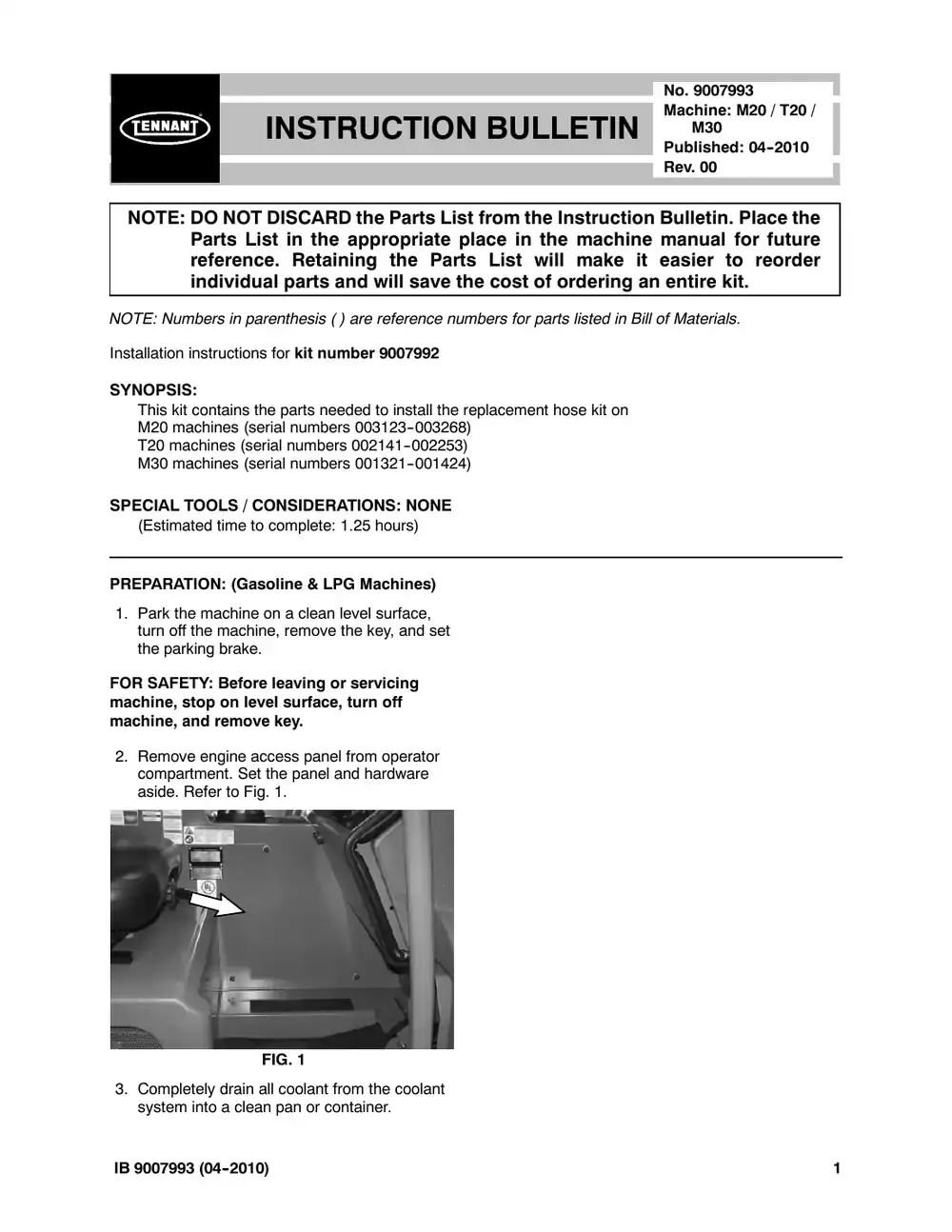
Tennant M20 instruction bulletin 9007993, page 1 of 6
Page 1 of 6 SES ref PF-UYCZ-4FPZ‌‌​⁠‍‍‌​‌​‍‌⁠‌⁠​⁠‌‌⁠​⁠‌​‌‍‍​​​​‌​‍‌​‌​‌‌​‌​⁠‍⁠‍‌⁠‍‌​‍‌⁠​​‍⁠‌
Text of this page
INSTRUCTION NOTE: DO NOT DISCARD the Parts List Parts List in the appropriate pla reference. Retaining the Parts individual parts and will save the NOTE: Numbers in parenthesis ( ) are reference num Installation instructions for kit number TN4201180 SYNOPSIS: This kit contains the parts needed to install the re M20 machines (serial numbers 003123--003268) T20 machines (serial numbers 002141--002253) M30 machines (serial numbers 001321--001424) SPECIAL TOOLS / CONSIDERATIONS: NONE (Estimated time to complete: 1.25 hours) PREPARATION: (Gasoline & LPG Machines) 1. Park the machine on a clean level surface, turn off the machine, remove the key, and set the parking brake. FOR SAFETY: Before leaving or servicing machine, stop on level surface, turn off machine, and remove key. 2. Remove engine access panel from operator compartment. Set the panel and hardware aside. Refer to Fig. 1. FIG. 1 3. Completely drain all coolant from the coolant system into a clean pan or container. IB 9007993 (04--2010) No. 9007993 Machine: M20 / T20 / N BULLETIN M30 Published: 04--2010 Rev. 00 from the Instruction Bulletin. Place the ace in the machine manual for future s List will make it easier to reorder e cost of ordering an entire kit. mbers for parts listed in Bill of Materials. eplacement hose kit on 1
Tennant M20 instruction bulletin 9007993, page 2 of 6
Page 2 of 6
Text of this page
INSTALLATION: (Gasoline Machines) Lower coolant Remove an tube with 90° br FIG 1. Disconnect the heater hose from the radiator and engine. Discard the heater hose and hose clamps. Refer to Fig. 1. 2. Remove the straight brass fitting from the radiator. Set the straight fitting aside. Refer to Fig. 1. 3. Remove the plug from the lower coolant tube. Discard the plug Refer to Fig. 1. 4. Install the 90° brass fitting (2) onto the lower coolant tube where the plug was previously located. Refer to Fig. 1 and Fig. 5. 5. Cut a 3” section of hose from the molded end of the radiator hose (6). 6. Cut a 24” section of hose from the 96” hose (5). 7. Install the adapter fitting (3) into the straight fitting left on the radiator. Refer to Fig. 5. 8. Install the saved straight fitting into the adapter fitting (3). Refer to Fig. 5. 2 Do Not remove this straight fitting Remove and discard Remove and set straight fitting aside Remove and discard Remove and Radiator discard 24” heater hose nd discard plug. Replace rass fitting (2) G. 1 9. Connect the plastic t--fitting (1) to the 28” radiator hose (6). Refer to Fig. 2 and Fig. 5. FIG. 2 10. Connect the 3” radiator hose (6) to plastic t--fitting (1). Refer to Fig. 2 and Fig. 5. 11. Use a hose clamp (4) to secure each hose from the previous steps to the plastic t--fitting (1). Refer to Fig. 2 and Fig. 5. IB 9007993 (04--2010)
Tennant M20 instruction bulletin 9007993, page 3 of 6
Page 3 of 6
Text of this page
12. Use a hose clamp (4) to connect the other end of the radiator hose (6) to the straight fitting attached to the radiator. Refer to Fig. 5. 13. Use a hose clamp (4) to connect the other end of the 3” hose (6) to the engine. Refer to Fig. 5. 14. Use a hose clamp (4) to connect the 24” hose (5) to the plastic t--fitting (1). Refer to Fig. 5. 15. Route the 24” hose (5) down through the wires connected to the alternator, along the engine, and down to the lower coolant tube. Refer to Fig. 3. FIG. 3 Lower coolant tube 2 4 FIG IB 9007993 (04--2010) 16. Use a hose clamp (4) to connect the 24” hose (5) to the 90° brass fitting (2) installed on the lower coolant tube. Refer to Fig. 4 and Fig. 5. FIG. 4 17. Refill the coolant system with coolant. 18. Start and run the machine. Observe the newly installed hoses, fittings, and connections for leaks. 19. Turn off the machine. Recheck the coolant level. Add coolant as necessary. Straight fitting 3 4 6 (28”) 1 4 4 6 (3”) 5 (24”) G. 5 3
Tennant M20 instruction bulletin 9007993, page 4 of 6
Page 4 of 6
Text of this page
INSTALLATION: (LPG Machines) LPG Regulator Lower coolant tube Remove Remove and and discard 38” discard hose FIG 1. Disconnect the 38” hose from the radiator and LPG regulation. Discard the heater hose and both hose clamps. Refer to Fig. 1. 2. Remove the straight brass fitting from the radiator. Set the straight fitting aside. Refer to Fig. 1. 3. Remove the plug from the lower coolant tube. Discard the plug Refer to Fig. 1. 4. Install the 90° brass fitting (2) onto the lower coolant tube. Refer to Fig. 3 and Fig. 6. 4 Do Not remove this straight fitting Remove and set straight fitting aside Remove and discard plug. Replace with 90° brass fitting (2) Remove and discard d ” G. 1 5. Install the adapter fitting (3) into the straight fitting left on the radiator. Refer to Fig. 6. 6. Install the saved straight fitting into the adapter fitting (3). Refer to Fig. 6. 7. Cut three 24” sections of hose from the 96” hose (5). 8. Use a hose clamp (4) to connect the three 24” hoses (6) to the plastic t--fitting (1). Refer to Fig. 6. IB 9007993 (04--2010)
Tennant M20 instruction bulletin 9007993, page 5 of 6
Page 5 of 6
Text of this page
9. Use a hose clamp (4) to connect one 24” hose (6) to the straight fitting installed in the radiator. Refer to Fig. 2 and Fig. 6. FIG. 2 10. Use a hose clamp (4) to connect the one 24” hose (5) to the LPG regulator. Refer to Fig. 4 and Fig. 6. FIG. 3 11. Route the 24” hose (5) down through the wires connected to the alternator, along the engine, and down to the lower coolant tube. Refer to Fig. 4. FIG. 4 IB 9007993 (04--2010) 12. Use a hose clamp (4) to connect the 24” rubber hose (5) to the 90° brass fitting (2) on the lower coolant tube. Refer to Fig. 5 and Fig. 6. FIG. 5 13. Refill the coolant system with coolant. 14. Start and run the machine. Observe the newly installed hoses, fittings, and connections for leaks. 15. Turn off the machine. Recheck the coolant level. Add coolant as necessary. 5
Tennant M20 instruction bulletin 9007993, page 6 of 6
Page 6 of 6
Text of this page
Straight fitting 3 2 LPG Regulator 4 1 5 (24”) Lower coolant tube 4 4 4 5 (24”) 5 (24”) 4 FIG. 6 Bill Of Materials For Hose Kit, Replmt [GM1.6L 2010] -- TN4201180 Tennant Ref. Part No. Description Qty. o TN4201180 ) Hose Kit, Replmt [GM1.6L 2010] 1 Y 1 TN4034918 Fitting, Plstc, Tee, BM10/BM10/BM10, Nyl 1 Y 2 TN4014601 Fitting, Brs, E90, EM10/PM06 1 Y 3 TN4038308 Fitting, Adapter, Orifice, PF06/PM06 1 Y 4 TN4017089 Clamp, Hose, Wormdrive, 0.56--1.06D, .56W 6 Y 5 TN4035153 ) Hose, Afmkt, Rbr, Heater, 0.62ID, 08FT 1 Y 6 TN4038615 Hose, Radiator, Mold, .75ID X .62ID (Gasoline machines only) 1 TENNANT COMPANY P. O. Box 1452 Minneapolis, MN 55440-1452 6 IB 9007993 (04--2010)

leaks. BILL OF MATERIALS FOR TUBE KIT, HYD, CASE DRAIN [M30]

Tennant instruction bulletin 9006383 rev. 01Published 07-2010Kit 9006384, 9006386

What it’s for: Replace the hydraulic case drain on M20 / T20 / M30 machines.

  • Machines: M20, M30, T20
  • M20: all
  • Power: gasoline, LPG and diesel

Time: 2 hours · Special tools: NONE

Safety warnings (from the bulletin, word for word)

  • FOR SAFETY: Before leaving or servicing machine, stop on level surface, turn off machine, and remove key.
  • FOR SAFETY: When servicing machine, block machine tires before jacking machine up. Use a hoist or jack that will support the weight of the machine. Jack machine up at designated locations only. Support machine with jack stands. 1

Parts

Parts for Tennant instruction bulletin 9006383
ItemPart numberQtyDescriptionPrice
TN4015310Old # 90063841leaks. BILL OF MATERIALS FOR TUBE KIT, HYD, CASE DRAIN [M30]KitCall for availability 800-440-6723
TN4015312Old # 90063861JF04STR, 020.0 1 Y 3 39210 FITTING, HYD, E90, JF04/JM04 1 Y 4 763115 TIE, CABLE, 6.0L, 1.25D MAX 4 Y 5 1055153 ) TUBE, HYD, BRUSH RETURN, W/ CD [M30] 1 BILL OF MATERIALS FOR TUBE KIT, HYD, CASE DRAIN [M20/T20]Kit$109.30/EA
1TN4028729Old # 555861FITTING, HYD, STR, JM04/OM04$6.20/EA
2TN4018068Old # 3872811HOSE, HYD, TC04, JF04E90/JF04STR, 020.0$41.60/EA
3TN4019344Old # 392101FITTING, HYD, E90, JF04/JM04$8.70/EA
4TN4011909Old # 7631154TIE, CABLE, 6.0L, 1.25D MAX$2.30/EA
5TN4038717Old # 10551531TUBE, HYD, BRUSH RETURN, W/ CD [M30]Call for availability 800-440-6723
1TN4028729Old # 555861FITTING, HYD, STR, JM04/OM04$6.20/EA
2TN4018068Old # 3872811HOSE, HYD, TC04, JF04E90/JF04STR, 020.0$41.60/EA
3TN4019344Old # 392101FITTING, HYD, E90, JF04/JM04$8.70/EA
4TN4011909Old # 7631154TIE, CABLE, 6.0L, 1.25D MAX$2.30/EA
5TN4038716Old # 10551391TUBE, HYD, BRUSH RETURN, W/ CD [M20/T20]$158.30/EA

Bulletin PDF: Sign in to view or downloadSign in to download

Installation instructions (4 pages)
Tennant M20 instruction bulletin 9006383, page 1 of 4
Page 1 of 4 SES ref PF-MPSG-N3MS‌‌​⁠‍‍‌​‌​‍‌⁠‌⁠​⁠‌‌⁠⁠‍‌⁠‍‌‍‍​​​‌​‍‌​​⁠​‌‍‌⁠​‍​‌‌​‍‍‌⁠​‍‌​⁠⁠​
Text of this page
INSTRUCTION B NOTE: DO NOT DISCARD the Parts List Parts List in the appropriate pla reference. Retaining the Parts individual parts and will save the NOTE: Numbers in parenthesis ( ) are reference num Installation instructions for kit numbers TN4015310 (M3 SYNOPSIS: This kit contains the parts needed to replace the h Please follow step-by-step instructions. SPECIAL TOOLS / CONSIDERATIONS: NONE (Estimated time to complete: 2 hours) When assembling / disassembling hydraulic com 1. Thoroughly clean outside of hydraulic component prevent contaminants from entering system. 2. Flush hoses and fittings with air, solvent, or hydra to prevent contaminants from entering system. 3. Mark hydraulic hoses with locations of where they hoses to proper locations. 4. Discard all hydraulic fluid drained from the system hydraulic reservoir. Hydraulic fluid is potentially da and local laws/regulations governing the disposal disposing hydraulic fluid. PREPARATION: 1. Completely empty the recovery and solution tanks. 2. Park the machine on a clean level surface, 3. Turn off the machine and remove both main brushes from the scrub head. Set the brushes aside. 4. Start the machine and completely lower the scrub head. 5. Turn off the machine, remove the key, and set the parking brake. FOR SAFETY: Before leaving or servicing machine, stop on level surface, turn off machine, and remove key. IB 9006383 (07--2010) No. 9006383 Machine: M20 / T20 / BULLETIN M30 Published: 07--2010 Rev. 01 from the Instruction Bulletin. Place the ace in the machine manual for future s List will make it easier to reorder e cost of ordering an entire kit. mbers for parts listed in Bill of Materials. 30) & TN4015312 (M20 / T20) hydraulic case drain on M20 / T20 / M30 machines. mponents: ts before disconnecting hydraulic hoses or fittings to aulic fluid and cap disconnected hoses or open ports y are attached. Markings make it easier to reconnect m. Use only new approved hydraulic fluid to replenish angerous to the environment. Obey all federal, state, of environmentally hazardous materials when 6. Chock the back of rear tires and jack up the front end of the machine. Refer to MACHINE JACKING in the MAINTENANCE section of the Operators Manual for additional information on how to safely jack up the machine. 7. Position jack stands under the front of the machine. FOR SAFETY: When servicing machine, block machine tires before jacking machine up. Use a hoist or jack that will support the weight of the machine. Jack machine up at designated locations only. Support machine with jack stands. 1
Tennant M20 instruction bulletin 9006383, page 2 of 4
Page 2 of 4
Text of this page
8. Remove the front skirt assembly from the machine. Set the front skirt assembly and all hardware aside. Refer to Fig. 1. Front of scrub head Remove and Remove and set set front skirt hardware aside assembly aside FIG. 1 9. Remove the brush return tube from the scrub head. Discard the brush return tube. Refer to Fig. 2. Disconnect from brush return tube Main Brush From M1 Motor (Front) Main Brush Motor (Rear) Disconnect return hose from brush return tube Disconnect from Remove and discard brush return tube Brush Return Tube FIG. 2 2 IB 9006383 (07--2010)
Tennant M20 instruction bulletin 9006383, page 3 of 4
Page 3 of 4
Text of this page
INSTALLATION: 1. Remove the plug from the center port of the front brush motor. Refer to Fig. 3. NOTE: Diagram reoriented to better show locations of parts on front brush motor. FIG. 3 2. Install the straight fitting (1) into the center port of the front brush motor. Refer to Fig. 3 and Fig. 7. 3. Connect the 20” hydraulic hose (2) to the straight fitting (1). Refer to Fig. 3, Fig. 4, and Fig. 7. NOTE: The 20” hydraulic hose must be oriented on the straight fitting (1) / front brush motor as shown in Fig. 4. FIG. 4 IB 9006383 (07--2010) 4. Install the 90˚ fitting (3) onto the new brush return tube (5). Orient the 90˚ fitting so it is pointing out parallel with brush return tube. the Refer to FIg. 5 and Fig. 7. FIG. 5 5. Position new the brush return tube (5) onto the scrub head where the old one had previously been located and connect the hose from the rear brush motor to the brush return tube. Refer to Fig. 2 and Fig. 7. 6. Connect the other end of the brush return tube (5) to the 90˚ fitting on the front brush motor. Refer to Fig. 2 and Fig. 7. 7. Connect the return hose to the brush return tube (5). Refer to Fig. 2 and Fig. 7. 8. Route the 20” hydraulic hose (2) along the brush return tube (5) and attach the hose to the 90˚ fitting (3) on the brush return tube. Refer to Fig. 6. FIG. 6 9. Use several cable ties (4) to secure the 20” hydraulic hose (2) to the brush return tube (5). 10. Reinstall the front skirt assembly onto the machine. Refer to Fig. 1. 3
Tennant M20 instruction bulletin 9006383, page 4 of 4
Page 4 of 4
Text of this page
1 From Main Brush M1 Motor (Front) Main Brush Motor (Rear) 2 3 5 FIG. 7 11. Remove the jack stands from under the 13. Reinstall both main brushes into the scrub machine and lower the machine to the head. ground. 14. Start and test the machine. Raise and lower 12. If necessary, top off the hydraulic system with the scrub head and operate the brushes to new hydraulic fluid. ensure they are functioning properly. Observe all new hydraulic connections for leaks. BILL OF MATERIALS FOR TUBE KIT, HYD, CASE DRAIN [M30] -- TN4015310 Tennant Ref. Part No. Description Qty. o TN4015310 ) TUBE KIT, HYD, CASE DRAIN [M30] 1 Y 1 TN4028729 FITTING, HYD, STR, JM04/OM04 1 Y 2 TN4018068 HOSE, HYD, TC04, JF04E90/JF04STR, 020.0 1 Y 3 TN4019344 FITTING, HYD, E90, JF04/JM04 1 Y 4 TN4011909 TIE, CABLE, 6.0L, 1.25D MAX 4 Y 5 TN4038717 ) TUBE, HYD, BRUSH RETURN, W/ CD [M30] 1 BILL OF MATERIALS FOR TUBE KIT, HYD, CASE DRAIN [M20/T20] -- TN4015312 Tennant Ref. Part No. Description Qty. o TN4015312 ) TUBE KIT, HYD, CASE DRAIN [M20/T2] 1 Y 1 TN4028729 FITTING, HYD, STR, JM04/OM04 1 Y 2 TN4018068 HOSE, HYD, TC04, JF04E90/JF04STR, 020.0 1 Y 3 TN4019344 FITTING, HYD, E90, JF04/JM04 1 Y 4 TN4011909 TIE, CABLE, 6.0L, 1.25D MAX 4 Y 5 TN4038716 ) TUBE, HYD, BRUSH RETURN, W/ CD [M20/T20] 1 TENNANT COMPANY P. O. Box 1452 Minneapolis, MN 55440-1452 4 IB 9006383 (07--2010)

Light Kit, Flsh, CI [M20 And T20]

Tennant instruction bulletin 340815 rev. 01Published 03-2007Kit 9001327

What it’s for: Install a flashing light kit on M20 and T20 machines.

  • Machines: M20, T20
  • M20: all
  • Power: gasoline, LPG and diesel
  • Applies to: lights

Time: 1 hour · Special tools: NONE

Safety warnings (from the bulletin, word for word)

  • FOR SAFETY: Before leaving or servicing machine, stop on level surface, set parking brake, turn off machine, and remove key.
  • WARNING: Always disconnect battery cables from machine before working on electrical components.

Parts

Parts for Tennant instruction bulletin 340815
ItemPart numberQtyDescriptionPrice
TN4019669Old # 90013271Light Kit, Flsh, CI [M20 And T20]Kit$444.00/EA
2TN4035367Old # 241962Screw, Pan, M5 X 0.8 X 20, SS$3.20/EA
3TN4042244Old # 190662Washer, Flat, #10$2.50/EA
4TN4041991Old # 097392Nut, Hex, Lock, M5 X 0.8, Nl, SS$3.30/EA
5TN4035919Old # 10194451Bracket, Sppt, Revl Light$55.20/EA
6TN4041992Old # 097404Screw, Hex, M8 X 1.25 X 20, SS$3.30/EA
7TN4035242Old # 10172184Washer, Flat, 0.32b 1.00d .12, SS$3.40/EA
8TN4036226Old # 10199711Harness, Warning / Backup [M20 & T20]$27.50/EA
9TN4013452Old # 462362Clamp, Cable, Stl, 0.25D X 0.56W, 1Hole$3.60/EA

Bulletin PDF: Sign in to view or downloadSign in to download

Installation instructions (4 pages)
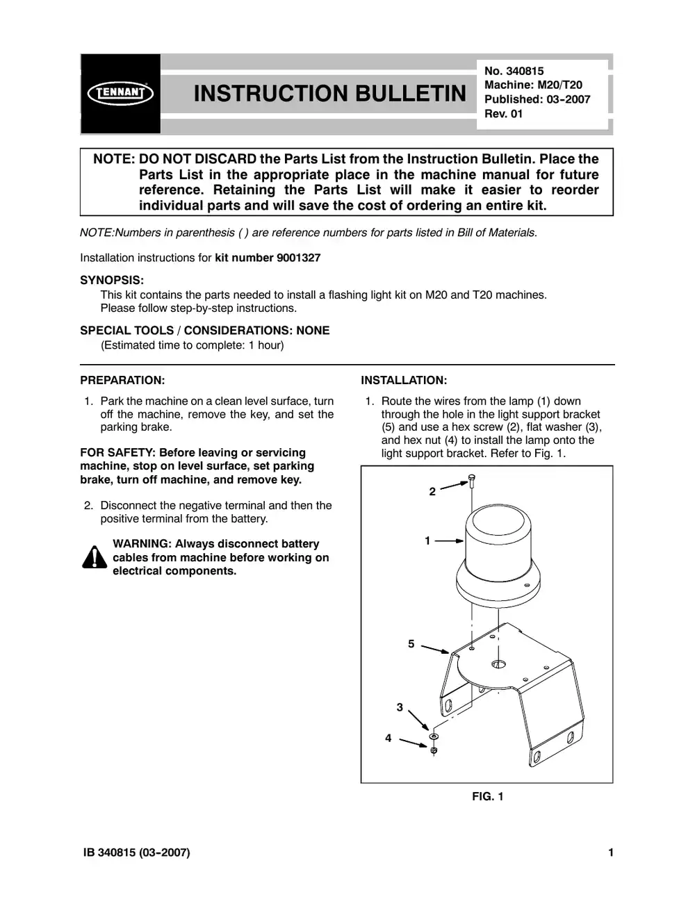
Tennant M20 instruction bulletin 340815, page 1 of 4
Page 1 of 4 SES ref PF-2AMB-MC4K‌‌​⁠‍‍‌​‌​‍‌⁠‌⁠​⁠‌‌⁠​⁠‍​‍‌‌‍​​​‌​‍‌​‍⁠‍‌⁠⁠‍⁠‌​⁠⁠‍​​​‌‌‌⁠⁠‍‍​
Text of this page
INSTRUCTION NOTE: DO NOT DISCARD the Parts List Parts List in the appropriate pla reference. Retaining the Parts individual parts and will save the NOTE:Numbers in parenthesis ( ) are reference numb Installation instructions for kit number TN4019669 SYNOPSIS: This kit contains the parts needed to install a flash Please follow step-by-step instructions. SPECIAL TOOLS / CONSIDERATIONS: NONE (Estimated time to complete: 1 hour) PREPARATION: 1. Park the machine on a clean level surface, turn off the machine, remove the key, and set the parking brake. FOR SAFETY: Before leaving or servicing machine, stop on level surface, set parking brake, turn off machine, and remove key. 2. Disconnect the negative terminal and then the positive terminal from the battery. WARNING: Always disconnect battery cables from machine before working on electrical components. IB 340815 (03--2007) No. 340815 Machine: M20/T20 N BULLETIN Published: 03--2007 Rev. 01 from the Instruction Bulletin. Place the ace in the machine manual for future s List will make it easier to reorder e cost of ordering an entire kit. bers for parts listed in Bill of Materials. hing light kit on M20 and T20 machines. INSTALLATION: 1. Route the wires from the lamp (1) down through the hole in the light support bracket (5) and use a hex screw (2), flat washer (3), and hex nut (4) to install the lamp onto the light support bracket. Refer to Fig. 1. 2 1 5 3 4 FIG. 1 1
Tennant M20 instruction bulletin 340815, page 2 of 4
Page 2 of 4
Text of this page
2. Route the wires from the lamp (1) through one cable clamp (9) and use a hex screw (2), two flat washers (3), and hex nut (4) to install the cable clamp underneath the lamp support bracket (5) and completely secure the lamp to the light support bracket. Refer to Fig. 2. 2 1 3 5 3 9 4 FIG. 2 3. Open the recovery tank cover and pull the main wire harness backup alarm and revolving light connector from between the recovery and solution tank. Connect the warning/backup harness (8) to the main wire harness. Refer to Fig. 3 or Fig. 4, and Fig. 9. FIG. 3 -- M20 Harness Location FIG. 4 -- T20 Harness Location 2 4. Route the warning/backup harness (8) through the notch in the solution tank and install a cable clamp (9) onto the warning/ backup harness. Refer to Fig. 6. 5. Use three hex screws (6) and three flat washers (7) to install the light support bracket (5) onto the solution tank. Refer to Fig. 5. 5 7 6 FIG. 5 6. Use a hex screw (6) and flat washer (7) to install the cable clamp (9) on the warning/ backup harness (8) onto light support bracket (5) and solution tank. Refer to Fig. 6. 5 9 6 7 FIG. 6 IB 340815 (03--2007)
Tennant M20 instruction bulletin 340815, page 3 of 4
Page 3 of 4
Text of this page
7. Connect the warning/backup harness (8) to the light (1). Refer to Fig. 8 and Fig. 9. 8. Neatly bundle remaining length of the warning/backup harness (8) and use a cable tie or electrical tape to hold the bundled wire together. Refer to Fig. 7. FIG. 7 2 3 4 6 7 9 FIG IB 340815 (03--2007) 9. Slide the main wire harness backup alarm and revolving light connector and attached connector from the warning/backup harness (8) back down between the recovery and solution tank and close the recovery tank cover. Refer to Fig. 3 or Fig. 4. 10. Reconnect the positive terminal and then the negative terminal to the battery. 11. Start the machine and test the light. 1 5 3 9 3 4 8 Connect to main wire harness G. 8 3
Tennant M20 instruction bulletin 340815, page 4 of 4
Page 4 of 4
Text of this page
FIG. 9 Bill of Materials for Light Kit, Flsh, CI [M20 And T20]--TN4019669 Tennant Ref. Part No. Description Qty. o TN4019669 ) Light Kit, Flsh, Ci [M20 And T20] 1 Yo 1 1017248 Lamp, Flasher, Amb [12--48 Vdc] 1 YY 9000879 Lens, Lamp, Amb, Strobe/Flasher 1 YY 9000845 Lamp, Bulb, Lamp, Flsh 1 YY 55272 Terminal, Bullet, Mal, .157d, 12ga 2 Y 2 TN4035367 ) Screw, Pan, M5 X 0.8 X 20, SS 2 Y 3 TN4042244 Washer, Flat, #10 2 Y 4 TN4041991 Nut, Hex, Lock, M5 X 0.8, Nl, SS 2 Y 5 TN4035919 Bracket, Sppt, Revl Light 1 Y 6 TN4041992 Screw, Hex, M8 X 1.25 X 20, SS 4 Y 7 TN4035242 ) Washer, Flat, 0.32b 1.00d .12, SS 4 Y 8 TN4036226 Harness, Warning / Backup [M20 & T20] 1 Y 9 TN4013452 Clamp, Cable, Stl, 0.25D X 0.56W, 1Hole 2 TENNANT COMPANY P. O. Box 1452 Minneapolis, MN 55440-1452 4 IB 340815 (03--2007)

Latch Kit, Cover, Soltn, Replmt [M20/T20]

Tennant instruction bulletin 9005111 rev. 00Published 09-2008Kit 9005165

What it’s for: Replace solution tank latches on M20 / T20 machines.

  • Machines: M20, T20
  • M20: all
  • Power: gasoline, LPG and diesel

Time: 10--20 minutes · Special tools: Pop Rivet

Safety warnings (from the bulletin, word for word)

  • FOR SAFETY: Before leaving or servicing machine, stop on level surface, turn off machine, and remove key.

Parts

Parts for Tennant instruction bulletin 9005111
ItemPart numberQtyDescriptionPrice
TN4014110Old # 90051651Latch Kit, Cover, Soltn, Replmt [M20/T20]Kit$120.00/EA
1TN4044235Old # 10397571Plate, Mtg, Latch$13.50/EA
2TN4027333Old # 3823204Screw, Pan, Phl, 12--16 X 0.50, F/Plstc$2.50/EA
3TN4039724Old # 10484741Catch, Latch, Tank Cover$10.20/EA
4TN4040232Old # 2222672Screw, Pan, Phl, 12--20 X 0.50, Fmg/AB$2.50/EA
5TN4039732Old # 10485121Bracket, Mtg, Latch, Tank Cover$18.60/EA
6TN4031145Old # 3679491Latch$35.40/EA
7TN4041936Old # 088752Rivet, Blind, .125D X 0.54 X .25D, Alm$3.40/EA

Bulletin PDF: Sign in to view or downloadSign in to download

Installation instructions (2 pages)
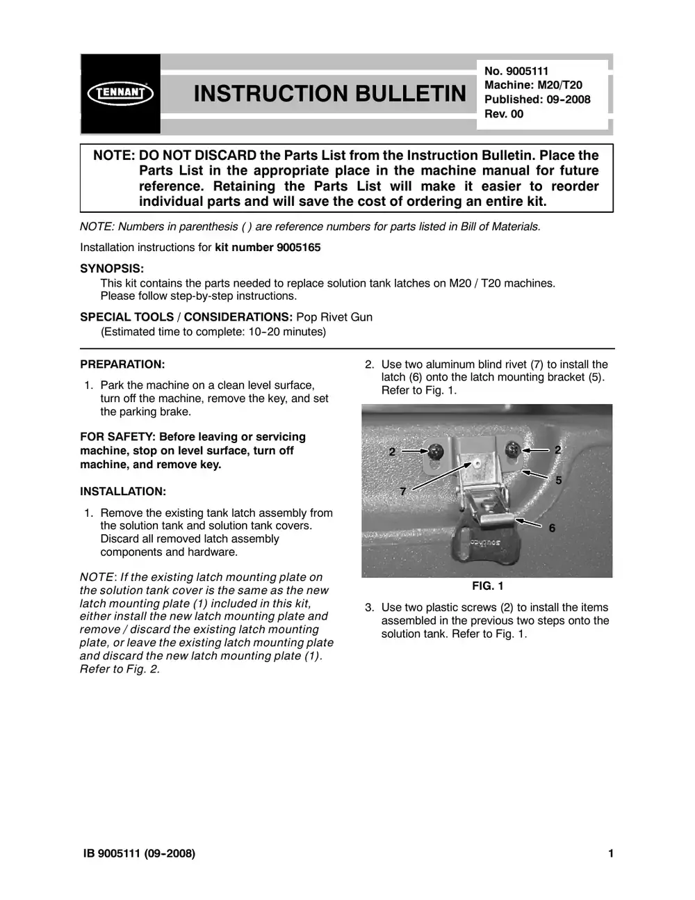
Tennant M20 instruction bulletin 9005111, page 1 of 2
Page 1 of 2 SES ref PF-QOA5-D5FA‌‌​⁠‍‍‌​‌​‍‌⁠‌⁠​⁠‌‌⁠‌​‌‍‌⁠⁠⁠​​​‌​‍‌​‌‍‌​‌​​‌⁠‍⁠‍​‍⁠‌‍​‌‌⁠‌⁠​
Text of this page
INSTRUCTION NOTE: DO NOT DISCARD the Parts List Parts List in the appropriate pla reference. Retaining the Parts individual parts and will save the NOTE: Numbers in parenthesis ( ) are reference num Installation instructions for kit number TN4014110 SYNOPSIS: This kit contains the parts needed to replace solu Please follow step-by-step instructions. SPECIAL TOOLS / CONSIDERATIONS: Pop Rivet (Estimated time to complete: 10--20 minutes) PREPARATION: 1. Park the machine on a clean level surface, turn off the machine, remove the key, and set the parking brake. FOR SAFETY: Before leaving or servicing machine, stop on level surface, turn off machine, and remove key. INSTALLATION: 1. Remove the existing tank latch assembly from the solution tank and solution tank covers. Discard all removed latch assembly components and hardware. NOTE: If the existing latch mounting plate on the solution tank cover is the same as the new latch mounting plate (1) included in this kit, either install the new latch mounting plate and remove / discard the existing latch mounting plate, or leave the existing latch mounting plate and discard the new latch mounting plate (1). Refer to Fig. 2. IB 9005111 (09--2008) No. 9005111 Machine: M20/T20 N BULLETIN Published: 09--2008 Rev. 00 from the Instruction Bulletin. Place the ace in the machine manual for future s List will make it easier to reorder e cost of ordering an entire kit. mbers for parts listed in Bill of Materials. ution tank latches on M20 / T20 machines. Gun 2. Use two aluminum blind rivet (7) to install the latch (6) onto the latch mounting bracket (5). Refer to Fig. 1. 2 2 5 7 6 FIG. 1 3. Use two plastic screws (2) to install the items assembled in the previous two steps onto the solution tank. Refer to Fig. 1. 1
Tennant M20 instruction bulletin 9005111, page 2 of 2
Page 2 of 2
Text of this page
4. Use two plastic screws (2) to install the latch mounting plate (1) onto the solution tank cover if the latch mounting plate was removed in Step 1. Refer to Fig. 2. 2 3 4 2 1 FIG. 2 5. Use two pan screws (4) to install the tank cover latch catch (3) onto the latch mounting plate (1) and solution tank cover. Refer to Fig. 2. NOTE: If there are no existing holes to secure the latch mounting plate (1) to the solution tank cover, drill an additional hole through each of the elongated holes in the latch mounting plate and the lip of the the solution tank cover. DO NOT drill completely through the top of the cover. Bill of Materials for Latch Kit, Cover Tennant Ref. Part No. Description o TN4014110 ) Latch Kit, Cover, Soltn, R Y 1 TN4044235 Plate, Mtg, Latch Y 2 TN4027333 Screw, Pan, Phl, 12--16 X Y 3 TN4039724 Catch, Latch, Tank Cover Y 4 TN4040232 Screw, Pan, Phl, 12--20 X Y 5 TN4039732 ) Bracket, Mtg, Latch, Tank Y 6 TN4031145 Latch Y 7 TN4041936 Rivet, Blind, .125D X 0.54 TENNANT P. O. Bo Minneapolis, M 2 6. Close the solution tank cover and use the newly installed solution cover latch to secure the cover shut. Refer to Fig. 3. 7. If necessary, loosen the two pan screws (4) to adjust the position of the tank cover latch catch (3) on the solution tank cover or the plastic screws (2) to adjust the position of the latch mounting bracket (5) on the solution tank if the latch does not adequately secure the cover into place, or if the cover is difficult to secure. Refer to Fig. 1 and Fig. 2. FIG. 3 r, Soltn, Replmt [M20/T20] -- TN4014110 Qty. Replmt [M20/T20] 1 1 X 0.50, F/Plstc 4 r 1 X 0.50, Fmg/AB 2 k Cover 1 1 4 X .25D, Alm 2 COMPANY ox 1452 MN 55440-1452 IB 9005111 (09--2008)

Hopper Kit, Modif, Screen, Filter

Tennant instruction bulletin 340870 rev. 01Published 08-2007Kit 9003789

What it’s for: Install/replace the filter tray on M20 machines (serial numbers 0000--2141).

  • Machines: M20
  • M20 SN 000000–002141
  • Power: gasoline, LPG and diesel

Time: 20 minutes · Special tools: NONE

Safety warnings (from the bulletin, word for word)

  • WARNING: Raised hopper may fall. Engage hopper support pin.
  • WARNING: Lift arm pinch point. Stay clear of hopper lift arms.
  • FOR SAFETY: Before leaving or servicing machine, stop on level surface, set parking brake, turn off machine, and remove key.

Parts

Parts for Tennant instruction bulletin 340870
ItemPart numberQtyDescriptionPrice
TN4017006Old # 90037891Hopper Kit, Modif, Screen, FilterKitCall for availability 800-440-6723
1TN4043553Old # 10379471Tray, Perma--Filter$127.10/EA

Bulletin PDF: Sign in to view or downloadSign in to download

Installation instructions (2 pages)
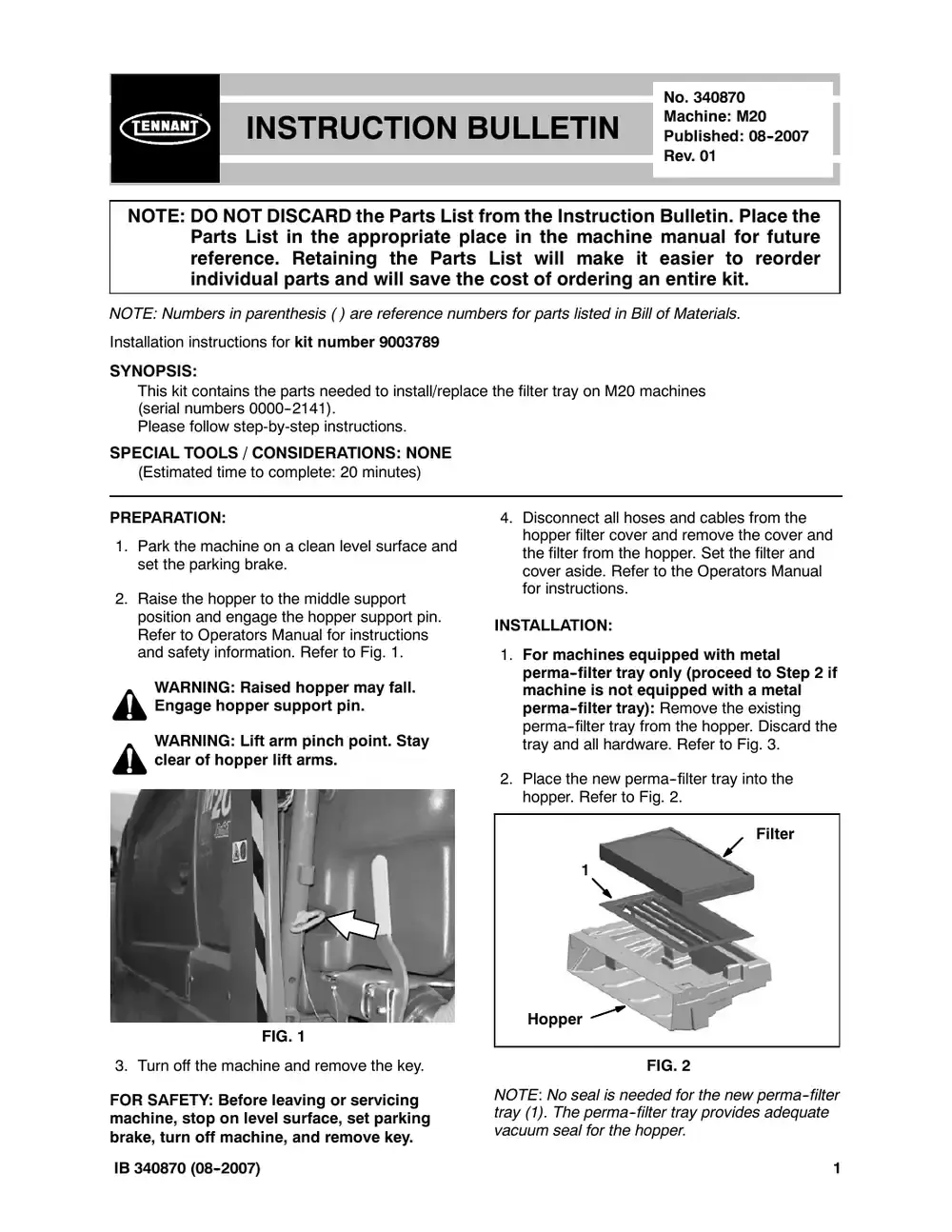
Tennant M20 instruction bulletin 340870, page 1 of 2
Page 1 of 2 SES ref PF-X6TN-AOP3‌‌​⁠‍‍‌​‌​‍‌⁠‌⁠​⁠‌‌⁠‌‍‍⁠‍‌⁠⁠​​​‌​‍‌​‍​​​‍⁠⁠‍​‌​‌‍‍‌‌‍​‌⁠‌⁠‌​
Text of this page
INSTRUCTION B NOTE: DO NOT DISCARD the Parts List Parts List in the appropriate pla reference. Retaining the Parts individual parts and will save the NOTE: Numbers in parenthesis ( ) are reference num Installation instructions for kit number TN4017006 SYNOPSIS: This kit contains the parts needed to install/replac (serial numbers 0000--2141). Please follow step-by-step instructions. SPECIAL TOOLS / CONSIDERATIONS: NONE (Estimated time to complete: 20 minutes) PREPARATION: 1. Park the machine on a clean level surface and set the parking brake. 2. Raise the hopper to the middle support position and engage the hopper support pin. Refer to Operators Manual for instructions and safety information. Refer to Fig. 1. WARNING: Raised hopper may fall. Engage hopper support pin. WARNING: Lift arm pinch point. Stay clear of hopper lift arms. FIG. 1 3. Turn off the machine and remove the key. FOR SAFETY: Before leaving or servicing machine, stop on level surface, set parking brake, turn off machine, and remove key. IB 340870 (08--2007) No. 340870 Machine: M20 BULLETIN Published: 08--2007 Rev. 01 from the Instruction Bulletin. Place the ace in the machine manual for future s List will make it easier to reorder e cost of ordering an entire kit. mbers for parts listed in Bill of Materials. ce the filter tray on M20 machines 4. Disconnect all hoses and cables from the hopper filter cover and remove the cover and the filter from the hopper. Set the filter and cover aside. Refer to the Operators Manual for instructions. INSTALLATION: 1. For machines equipped with metal perma--filter tray only (proceed to Step 2 if machine is not equipped with a metal perma--filter tray): Remove the existing perma--filter tray from the hopper. Discard the tray and all hardware. Refer to Fig. 3. 2. Place the new perma--filter tray into the hopper. Refer to Fig. 2. Filter 1 Hopper FIG. 2 NOTE: No seal is needed for the new perma--filter tray (1). The perma--filter tray provides adequate vacuum seal for the hopper. 1
Tennant M20 instruction bulletin 340870, page 2 of 2
Page 2 of 2
Text of this page
3. Reinstall the filter into the hopper. Refer to 5. Start the machine, lower the hopper, and test Fig. 2 and Fig. 3. the machine. 4. Reinstall the hopper cover onto the hopper. Reattach all cables and hoses to the hopper cover. Refer to the Operators Manual for instructions. Refer to Fig. 3. Remove and set hopper cover and filter aside. Remove and discard existing perma--filter tray and hardware (if machine is equipped with these items). FIG. 3 Bill of Materials for Hopper Kit, Modif, Screen, Filter--TN4017006 Tennant Ref. Part No. Description Qty. o TN4017006 ) Hopper Kit, Modif, Screen, Filter 1 Y 1 TN4043553 Tray, Perma--Filter 1 TENNANT COMPANY P. O. Box 1452 Minneapolis, MN 55440-1452 2 IB 340870 (08--2007)

Screen Kit, Replmt, Hopper [M20]

Tennant instruction bulletin 340863 rev. 00Published 08-2007Kit 9003774

What it’s for: Replace the hopper screen on M20 machines.

  • Machines: M20
  • M20: all
  • Power: gasoline, LPG and diesel

Time: 1 hour · Special tools: NONE

Safety warnings (from the bulletin, word for word)

  • WARNING: Raised hopper may fall. Engage hopper support pin.
  • WARNING: Lift arm pinch point. Stay clear of hopper lift arms.
  • FOR SAFETY: Before leaving or servicing machine, stop on level surface, set parking brake, turn off machine, and remove key.

Parts

Parts for Tennant instruction bulletin 340863
ItemPart numberQtyDescriptionPrice
TN4017005Old # 90037741Screen Kit, Replmt, Hopper [M20]Kit$260.50/EA
1TN4044019Old # 10391631Screen Wldt, Hppr$242.00/EA
2TN4041943Old # 090101Screw, Hex, M8 X 1.25 X 25, SS$3.30/EA
3TN4035242Old # 10172182Washer, Flat, 0.32B 1.00D .12, SS$3.40/EA
4TN4040233Old # 2222681Washer, Flat, 0.38B 1.25D .12, Neo$4.00/EA
5TN4044026Old # 10392151Angle, Retainer$11.10/EA
6TN4041929Old # 087131Nut, Hex, Lock, M8 X 1.25, NL, SS$3.30/EA

Bulletin PDF: Sign in to view or downloadSign in to download

Installation instructions (4 pages)
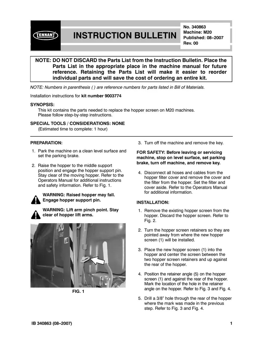
Tennant M20 instruction bulletin 340863, page 1 of 4
Page 1 of 4 SES ref PF-YRBE-NHML‌‌​⁠‍‍‌​‌​‍‌⁠‌⁠​⁠‌‌⁠​​‍⁠‌‍‌​​​​‌​‍‌​‌‌‍‍​⁠⁠‍‌⁠​‍‍‌‌‍​‍⁠⁠‌‌⁠‌
Text of this page
INSTRUCTION NOTE: DO NOT DISCARD the Parts List Parts List in the appropriate pla reference. Retaining the Parts individual parts and will save the NOTE: Numbers in parenthesis ( ) are reference num Installation instructions for kit number TN4017005 SYNOPSIS: This kit contains the parts needed to replace the h Please follow step-by-step instructions. SPECIAL TOOLS / CONSIDERATIONS: NONE (Estimated time to complete: 1 hour) PREPARATION: 1. Park the machine on a clean level surface and set the parking brake. 2. Raise the hopper to the middle support position and engage the hopper support pin. Stay clear of the moving hopper. Refer to the Operators Manual for additional instructions and safety information. Refer to Fig. 1. WARNING: Raised hopper may fall. Engage hopper support pin. WARNING: Lift arm pinch point. Stay clear of hopper lift arms. FIG. 1 IB 340863 (08--2007) No. 340863 Machine: M20 N BULLETIN Published: 08--2007 Rev. 00 from the Instruction Bulletin. Place the ace in the machine manual for future s List will make it easier to reorder e cost of ordering an entire kit. mbers for parts listed in Bill of Materials. hopper screen on M20 machines. 3. Turn off the machine and remove the key. FOR SAFETY: Before leaving or servicing machine, stop on level surface, set parking brake, turn off machine, and remove key. 4. Disconnect all hoses and cables from the hopper filter cover and remove the cover and the filter from the hopper. Set the filter and cover aside. Refer to the Operators Manual for additional information. INSTALLATION: 1. Remove the existing hopper screen from the hopper. Discard the hopper screen. Refer to Fig. 2. 2. Turn the hopper screen retainers so they are pointed away from where the new hopper screen (1) will be installed. 3. Place the new hopper screen (1) into the hopper and center the screen between the two hopper screen retainers and up against the rear of the hopper. 4. Position the retainer angle (5) on the hopper screen (1) and against the rear of the hopper. Mark the location of the hole in the retainer angle on the hopper. Refer to Fig. 3 and Fig. 4. 5. Drill a 3/8” hole through the rear of the hopper where the mark was made in the previous step. Refer to Fig. 3 and Fig. 4. 1
Tennant M20 instruction bulletin 340863, page 2 of 4
Page 2 of 4
Text of this page
6. Use a hex screw (2), two steel flat washers (3), a rubber washer (4), and a hex nut (6) to mount the retainer angle (5) onto the hopper. Refer to Fig. 3. 7. Center the hopper screen (1) between the two filter screen retainers, up against the rear of the hopper and use the front hopper screen retainer and the retaining (5) angle to secure the hopper screen into the hopper. Refer to Fig. 3. Remove and discard existing hopper screen. Replace with new hopper screen (1). FIG 2 8. Attach the squeegee vacuum hose to the hopper screen (1). 9. Insert the filter into the hopper and reinstall the hopper cover onto the hopper. Reconnect all hoses and cables to the hopper cover. Refer to the Operators Manual for additional information. 10. Start the machine, lower the hopper, and test the machine. Do not remove screen retainers. Retainers must remain in place to prevent hopper from leaking. Turn retainers away so new hopper screen (1) is easier to install G. 2 IB 340863 (08--2007)
Tennant M20 instruction bulletin 340863, page 3 of 4
Page 3 of 4
Text of this page
5 3 6 Squeegee vacuum 1 hose 2 3 4 FIG. 3 FIG. 4 IB 340863 (08--2007) 3
Tennant M20 instruction bulletin 340863, page 4 of 4
Page 4 of 4
Text of this page
Bill of Materials for Screen Kit, Replmt, Hopper [M20]--TN4017005 Tennant Ref. Part No. Description Qty. o TN4017005 ) Screen Kit, Replmt, Hopper [M20] 1 Y 1 TN4044019 Screen Wldt, Hppr 1 Y 2 TN4041943 Screw, Hex, M8 X 1.25 X 25, SS 1 Y 3 TN4035242 Washer, Flat, 0.32B 1.00D .12, SS 2 Y 4 TN4040233 Washer, Flat, 0.38B 1.25D .12, Neo 1 Y 5 TN4044026 Angle, Retainer 1 Y 6 TN4041929 Nut, Hex, Lock, M8 X 1.25, NL, SS 1 TENNANT COMPANY P. O. Box 1452 Minneapolis, MN 55440-1452 4 IB 340863 (08--2007)

A/V Kit, Strobe, CI [M20/T20]

Tennant instruction bulletin 340857 rev. 00Published 03-2007Kit 9003489

What it’s for: Install a strobe light/alarm kit on M20 and T20 machines.

  • Machines: M20, T20
  • M20: all
  • Power: gasoline, LPG and diesel
  • Applies to: overhead guard, lights

Time: 1.5 hours · Special tools: NONE

Safety warnings (from the bulletin, word for word)

  • FOR SAFETY: Before leaving or servicing machine, stop on level surface, set parking brake, turn off machine, and remove key.
  • WARNING: Always disconnect battery cables from machine before working on electrical components. NOTE: If installing the strobe light (13) onto the bracket (5), proceed to the instructions beginning on this page. If installing the strobe light (13) onto the overhead guard, proceed to the instructions starting on page 6.

Parts

Parts for Tennant instruction bulletin 340857
ItemPart numberQtyDescriptionPrice
TN4016755Old # 90034891A/V Kit, Strobe, CI [M20/T20]KitCall for availability 800-440-6723
1TN4011838Old # 619201Alarm Assy, Backup, 12--24vdc 82--107dbaCall for availability 800-440-6723
2TN4035367Old # 241964Screw, Pan, M5 X 0.8 X 20, SS$3.20/EA
3TN4042244Old # 190664Washer, Flat, #10$2.50/EA
4TN4041991Old # 097394Nut, Hex, Lock, M5 X 0.80, NL, SS$3.30/EA
5TN4035919Old # 10194451Bracket, Sppt, Revl Light$55.20/EA
6TN4041992Old # 097404Screw, Hex, M8 X 1.25 X 20, SS$3.30/EA
7TN4035242Old # 10172184Washer, Flat, 0.32b 1.00d .12, SS$3.40/EA
8TN4036226Old # 10199711Harness, Warning / Backup [M20 & T20]$27.50/EA
9TN4036203Old # 10196471Harness, Warning / OHG [M20]$23.56/EA
11TN4014138Old # 492662Tie, Cable, Nyl, 07.3L .19W 1.8 Max D$2.50/EA
12TN4011909Old # 7631154Tie, Cable, 6.0L, 1.25D Max$2.30/EA
13TN4035245Old # 10172501Light, Strobe, Amb, 12--48VDCCall for availability 800-440-6723
14TN4013452Old # 462362Clamp, Cable, Stl, 0.26D X 0.56W, 1 Hole$3.60/EA

Bulletin PDF: Sign in to view or downloadSign in to download

Installation instructions (12 pages)
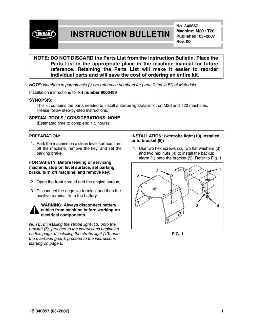
Tennant M20 instruction bulletin 340857, page 1 of 12
Page 1 of 12 SES ref PF-GDEK-S6P7‌‌​⁠‍‍‌​‌​‍‌⁠‌⁠​⁠‌‌⁠‍‌⁠​‍⁠⁠‍​​​‌​‍‌​‌⁠⁠‌⁠‌​‌⁠‍‌⁠‌⁠‌‍⁠‌⁠‍‌‌​‍
Text of this page
INSTRUCTION NOTE: DO NOT DISCARD the Parts List Parts List in the appropriate pla reference. Retaining the Parts individual parts and will save the NOTE: Numbers in parenthesis ( ) are reference num Installation instructions for kit number TN4016755 SYNOPSIS: This kit contains the parts needed to install a stro Please follow step-by-step instructions. SPECIAL TOOLS / CONSIDERATIONS: NONE (Estimated time to complete: 1.5 hours) PREPARATION: 1. Park the machine on a clean level surface, turn off the machine, remove the key, and set the parking brake. FOR SAFETY: Before leaving or servicing machine, stop on level surface, set parking brake, turn off machine, and remove key. 2. Open the front shroud and the engine shroud. 3. Disconnect the negative terminal and then the positive terminal from the battery. WARNING: Always disconnect battery cables from machine before working on electrical components. NOTE: If installing the strobe light (13) onto the bracket (5), proceed to the instructions beginning on this page. If installing the strobe light (13) onto the overhead guard, proceed to the instructions starting on page 6. IB 340857 (03--2007) No. 340857 Machine: M20 / T20 N BULLETIN Published: 03--2007 Rev. 00 from the Instruction Bulletin. Place the ace in the machine manual for future s List will make it easier to reorder e cost of ordering an entire kit. mbers for parts listed in Bill of Materials. obe light/alarm kit on M20 and T20 machines. INSTALLATION: (w/strobe light (13) installed onto bracket (5)) 1. Use two hex screws (2), two flat washers (3), and two hex nuts (4) to install the backup alarm (1) onto the bracket (5). Refer to Fig. 1. 2 1 5 3 4 FIG. 1 1
Tennant M20 instruction bulletin 340857, page 2 of 12
Page 2 of 12
Text of this page
2. Route the wires from the strobe light (13) down through the hole in the light support bracket (5) and use a hex screw (2), flat washer (3), and hex nut (4) to install the light onto the bracket. Refer to Fig. 2. 2 13 5 3 4 FIG. 2 3. Route the wires from the strobe light (13) through a cable clamp (9) and use a hex screw (2), two flat washers (3), and hex nut (4) to install the cable clamp underneath the lamp support bracket (5) and completely secure the light to the bracket. Refer to Fig. 3. 2 13 3 5 3 14 4 FIG. 3 2 4. Open the recovery tank cover and pull the main wire harness backup alarm and revolving light connector from between the recovery and solution tank. Connect the warning/backup harness (8) to the main wire harness. Refer to Fig. 4 or Fig. 5, and Fig. 8. FIG. 4 -- M20 Harness Location FIG. 5 -- T20 Harness Location 5. Route the warning/backup harness (8) through the notch in the solution tank and install a cable clamp (9) onto the harness. Refer to Fig. 8. IB 340857 (03--2007)
Tennant M20 instruction bulletin 340857, page 3 of 12
Page 3 of 12
Text of this page
6. Use three hex screws (6) and three flat washers (7) to install the bracket (5) onto the back of the machine. Refer to Fig. 6. 5 7 6 FIG. 6 7. Use a hex screw (6) and flat washer (7) to install the cable clamp (9) on the warning/ backup harness (8) onto light support bracket (5) and solution tank. Refer to Fig. 7. 5 9 6 7 FIG. 7 IB 340857 (03--2007) 8. Connect the wires from the backup alarm (1) and the strobe light (13) to the warning/ backup harness (8). Refer to Fig. 4. 9. Route excess cable from the main wire harness and the warning/backup harness (8) back down between the recovery and solution tank. Refer to Fig. 3 and Fig. 4. 10. Reconnect the positive terminal and then the negative terminal to the battery. 11. Start the machine and move the machine in reverse. The backup alarm should sound while machine is moving in reverse. The light should function while the engine is operating. 3
Tennant M20 instruction bulletin 340857, page 4 of 12
Page 4 of 12
Text of this page
2 Note: Following items are not used when strobe light (13) is installed onto support bracket (5): (9) TN4036203 Overhead Guard Warning Harness--Qty 1 (10) 10632--17 Rubber Grommet--Qty 4 (11) TN4014138 7.3” Nylon Cable Tie--Qty 2 13 (12) TN4011909 6” Nylon Cable Tie--Qty 4 2 1 3 4 5 8 3 4 6 7 14 14 3 4 FIG. 8 4 IB 340857 (03--2007)
Tennant M20 instruction bulletin 340857, page 5 of 12
Page 5 of 12
Text of this page
Backup / Warning Harness (9) Main Wire Harness FIG. 9 IB 340857 (03--2007) 5
Tennant M20 instruction bulletin 340857, page 6 of 12
Page 6 of 12
Text of this page
INSTALLATION: (w/strobe light (13) installed onto overhead guard) 1. Pull the insulation away from the operator compartment panel and drill a 13/16” hole into the panel. If there is already a hole in the panel, remove the plug from the hole. Refer to Fig. 1 and Fig. 2. FIG. 1 48.08 20.89 [1.893] [0.822] 59.90 [2.358] FIG. 2 6 2. Insert a grommet (10) into the hole in the operator compartment panel and the hole on top the overhead guard. Refer to Fig. 3 and Fig. 4. FIG. 3 4 3 13 10 2 FIG. 4 3. Route the wires from the strobe light (13) down through the grommet (10) installed in the overhead guard and use two hex screws (2), two flat washers (3), and two hex nuts (4) to install the light onto the overhead guard. Refer to Fig. 4. 4. Connect the warning/overhead harness (9) to the main wire harness, route the warning/ overhead harness through the grommet (10) installed in the operator compartment panel, up along leg of the overhead guard, and to the rear cross member of the overhead guard. Refer to Fig. 9 and Fig. 10. IB 340857 (03--2007)
Tennant M20 instruction bulletin 340857, page 7 of 12
Page 7 of 12
Text of this page
5. Insert a grommet (10) into the rear hole in the rear cross member of the overhead guard and route the warning/overhead harness (9) through the grommet and the front hole in the rear cross member. Refer to Fig. 5. Install first, before routing warning/ overhead harness (9) through cross member 10 10 Install after routing warning/ overhead harness (9) through cross member FIG. 5 6. Slide the remaining grommet (10) onto the warning/overhead harness (9) and insert the grommet into the front hole in the rear cross member of the overhead guard. Refer to Fig. 5. 7. Route the warning/OHG harness (9) through the notch in the overhead guard insulation and connect the harness to the strobe light (13). Refer to Fig. 6 and Fig. 10. FIG. 6 IB 340857 (03--2007) 8. Use four cable ties (12) to secure the warning/ overhead harness (9) to the leg of the overhead guard. Refer to Fig. 7 and Fig. 8. FIG. 7 FIG. 8 9. Use two cable ties (11) to secure the warning/ overhead harness (9) to the top of the overhead guard. Refer to Fig. 12. 10. Use two hex screws (2), two flat washers (3), and two hex nuts (4) to install the backup alarm (1) onto the bracket (5). Refer to Fig. 9. 2 1 5 3 4 FIG. 9 7
Tennant M20 instruction bulletin 340857, page 8 of 12
Page 8 of 12
Text of this page
11. Open the recovery tank cover and pull the main wire harness backup alarm connector from between the recovery and solution tank. Connect the warning/backup harness (8) to the main wire harness. Refer to Fig. 10 or Fig. 11, and Fig. 14. FIG. 10 -- M20 Harness Location FIG. 11 -- T20 Harness Location 12. Route the warning/backup harness (8) through the notch in the solution tank and install a cable clamp (9) onto the harness. Refer to Fig. 8. 8 13. Connect the wires from the backup alarm (1) to the warning/ backup harness (8). Refer to Fig. 14. 14. Neatly bundle the flashing light wires on the warning/ backup harness (8) and secure them to the harness with either cable ties of electrical tape. 15. Route excess cable from the main wire harness and the warning/backup harness (8) back down between the recovery and solution tank. Refer to Fig. 3 and Fig. 4. 16. Reconnect the negative battery cable and then the positive terminal to the battery. 17. Start the machine and move the machine in reverse. The backup alarm should sound while machine is moving in reverse. The light should function while the engine is operating. IB 340857 (03--2007)
Tennant M20 instruction bulletin 340857, page 9 of 12
Page 9 of 12
Text of this page
4 3 13 13 10 2 Connect to wires from strobe light (13) FRONT Locations for cable ties (11) securing warning/overhead harnes (9) to top of overhead guard REAR FIG IB 340857 (03--2007) REAR 12 Refer to Fig. 7 and Fig. 8 for locations of wire ties (12) on leg of overhead guard 9 10 Connect to main wire harness ss G. 12 9
Tennant M20 instruction bulletin 340857, page 10 of 12
Page 10 of 12
Text of this page
Main Wire Harness Warning/OHG Harness (9) FIG. 13 10 IB 340857 (03--2007)
Tennant M20 instruction bulletin 340857, page 11 of 12
Page 11 of 12
Text of this page
Backup / Warning Harness (9) Main Wire Harness FIG. 14 IB 340857 (03--2007) 11
Tennant M20 instruction bulletin 340857, page 12 of 12
Page 12 of 12
Text of this page
Bill of Materials for A/V Kit, Strobe, CI [M20/T20]--TN4016755 Tennant Ref. Part No. Description Qty. o TN4016755 A/V Kit, Strobe, CI [M20/T20] 1 Y 1 TN4011838 Alarm Assy, Backup, 12--24vdc 82--107dba 1 Y 2 TN4035367 Screw, Pan, M5 X 0.8 X 20, SS 4 Y 3 TN4042244 Washer, Flat, #10 4 Y 4 TN4041991 Nut, Hex, Lock, M5 X 0.80, NL, SS 4 Y 5 TN4035919 Bracket, Sppt, Revl Light 1 Y 6 TN4041992 Screw, Hex, M8 X 1.25 X 20, SS 4 Y 7 TN4035242 Washer, Flat, 0.32b 1.00d .12, SS 4 Y 8 TN4036226 Harness, Warning / Backup [M20 & T20] 1 Y 9 TN4036203 Harness, Warning / OHG [M20] 1 Y 10 10632--17 Grommet, Rbr, 0.50ID, F/0.8H, .12 Matl 4 Y 11 TN4014138 Tie, Cable, Nyl, 07.3L .19W 1.8 Max D 2 Y 12 TN4011909 Tie, Cable, 6.0L, 1.25D Max 4 Y 13 TN4035245 Light, Strobe, Amb, 12--48VDC 1 Y 14 TN4013452 Clamp, Cable, Stl, 0.26D X 0.56W, 1 Hole 2 TENNANT COMPANY P. O. Box 1452 Minneapolis, MN 55440-1452 12 IB 340857 (03--2007)

Hose Kit, Hyd, Propel, CI [M20/T20]

Tennant instruction bulletin 340860 rev. 00Published 09-2007Kit 1039147, 1039148

What it’s for: Install a hydraulic propel hose kit on M20 / T20 machines.

  • Machines: M20, T20
  • M20: all
  • Power: gasoline, LPG and diesel

Time: 3 hours · Special tools: NONE

Safety warnings (from the bulletin, word for word)

  • FOR SAFETY: Before leaving or servicing machine, stop on level surface, set parking brake, turn off machine, and remove key.

Parts

Parts for Tennant instruction bulletin 340860
ItemPart numberQtyDescriptionPrice
TN4044014Old # 10391471Hose Kit, Hyd, Propel, CI [M20/T20]KitCall for availability 800-440-6723
TN4044015Old # 10391481JF10Str, 063.0 1 Y 2 763116 Tie, Cable, Nyl, 15.3L. W 4.5 Max D 2 Bill of Materials for Hose Kit, Hyd, Propel, CI [M20/T20]Kit$108.10/EA
1TN4033273Old # 10234881Hose, Hyd, Spcl, JF10E90/JF10Str, 063.0$135.50/EA
2TN4011910Old # 7631162Tie, Cable, Nyl, 15.3L. W 4.5 Max D$3.40/EA
1TN4043678Old # 10385691Hose, Hyd, Spcl, JF10Str/JF10Str, 56.5$91.80/EA
2TN4015060Old # 540171Fitting, Hyd, E45, JF10/JM10$48.90/EA
3TN4011910Old # 7631162Tie, Cable, Nyl, 15.3L. W 4.5 Max D$3.40/EA

Bulletin PDF: Sign in to view or downloadSign in to download

Installation instructions (8 pages)
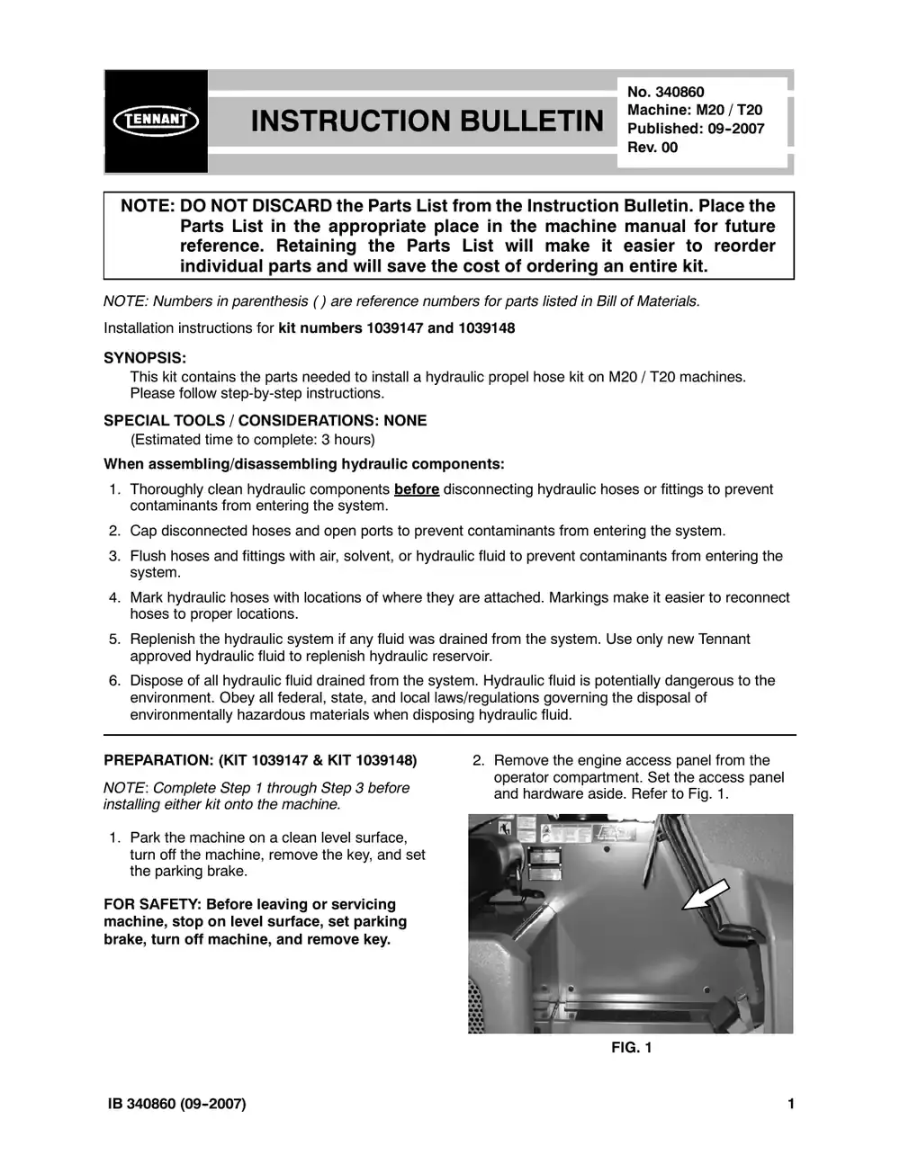
Tennant M20 instruction bulletin 340860, page 1 of 8
Page 1 of 8 SES ref PF-7EV5-TQQV‌‌​⁠‍‍‌​‌​‍‌⁠‌⁠​⁠‌‌⁠‌‌‍‍⁠‌⁠‍​​​‌​‍‌​‌⁠⁠⁠​‌⁠‍‍‍‌‌‌​‍​⁠‍‍‍⁠‌‌‍
Text of this page
INSTRUCTION NOTE: DO NOT DISCARD the Parts List Parts List in the appropriate pla reference. Retaining the Parts individual parts and will save the NOTE: Numbers in parenthesis ( ) are reference num Installation instructions for kit numbers TN4044014 and SYNOPSIS: This kit contains the parts needed to install a hydr Please follow step-by-step instructions. SPECIAL TOOLS / CONSIDERATIONS: NONE (Estimated time to complete: 3 hours) When assembling/disassembling hydraulic comp 1. Thoroughly clean hydraulic components before d contaminants from entering the system. 2. Cap disconnected hoses and open ports to preve 3. Flush hoses and fittings with air, solvent, or hydra system. 4. Mark hydraulic hoses with locations of where they hoses to proper locations. 5. Replenish the hydraulic system if any fluid was dr approved hydraulic fluid to replenish hydraulic res 6. Dispose of all hydraulic fluid drained from the sys environment. Obey all federal, state, and local law environmentally hazardous materials when dispos PREPARATION: (KIT TN4044014 & KIT TN4044015) NOTE: Complete Step 1 through Step 3 before installing either kit onto the machine. 1. Park the machine on a clean level surface, turn off the machine, remove the key, and set the parking brake. FOR SAFETY: Before leaving or servicing machine, stop on level surface, set parking brake, turn off machine, and remove key. IB 340860 (09--2007) No. 340860 Machine: M20 / T20 N BULLETIN Published: 09--2007 Rev. 00 from the Instruction Bulletin. Place the ace in the machine manual for future s List will make it easier to reorder e cost of ordering an entire kit. mbers for parts listed in Bill of Materials. d TN4044015 raulic propel hose kit on M20 / T20 machines. ponents: disconnecting hydraulic hoses or fittings to prevent ent contaminants from entering the system. aulic fluid to prevent contaminants from entering the y are attached. Markings make it easier to reconnect rained from the system. Use only new Tennant servoir. stem. Hydraulic fluid is potentially dangerous to the ws/regulations governing the disposal of sing hydraulic fluid. 2. Remove the engine access panel from the operator compartment. Set the access panel and hardware aside. Refer to Fig. 1. FIG. 1 1
Tennant M20 instruction bulletin 340860, page 2 of 8
Page 2 of 8
Text of this page
3. Remove the LPG tank (if machine is equipped with LPG fuel system) to access the hose clamp located on the inner side of the operator compartment. Refer to Operators Manual for instructions how to remove the LPG tank. Refer to Fig. 2. FIG. 2 NOTE: After completing Step 1 through Step 3: If installing Kit TN4044014, proceed to the instructions below. If installing Kit TN4044015, proceed to the instructions on page 4. If installing both kits, proceed to the instructions on page 6. INSTALLATION: (INSTALL KIT #TN4044014 ONLY) 1. Locate hydraulic hose (A) connected to the propel pump and wheel drive motor. Note where/how hydraulic hose (A) is routed. The new hydraulic hose (1) must be routed the same as hydraulic hose (A). Refer to Fig. 6. 2. Loosen the hose clamp and remove hydraulic hose (A) from the clamp. Refer to Fig. 2, Fig. 3, and Fig. 6. FIG. 3 2 3. Reinstall the hose clamp. Be sure the markings on the remaining hoses remain positioned as shown in Fig. 3. 4. Disconnect hydraulic hose (A) from the propel pump and the wheel drive motor, pull the hydraulic hose from the machine, and discard the hose. Refer to Fig. 6. 5. Loosely thread the new hydraulic hose (1) onto the fitting on the wheel drive motor where hydraulic hose (A) was previously installed. Refer to Fig. 6. 6. Route the hydraulic hose (1) toward the hose clamp located on the inner side of the operator compartment and use two cable ties (2) to secure the hydraulic hose to the other two hoses it is routed near. Refer to Fig. 4. FIG. 4 7. Cut the ends from the cable ties (2). 8. Route the hydraulic hose (1) the rest of the way to the hose clamp. Refer to Fig. 2 and Fig. 6. 9. Loosen the hose clamp, position the hydraulic hose (1) so the CLAMP LOCATION CENTER LINE markings on the label are centered in the hose clamp, and reinstall the hose clamp. Refer to Fig. 2, Fig. 3, and Fig. 5. FIG. 5 IB 340860 (09--2007)
Tennant M20 instruction bulletin 340860, page 3 of 8
Page 3 of 8
Text of this page
10. Route the hydraulic hose (1) from the hose clamp to the propel pump. Refer to Fig. 6. 11. Loosely thread the 90˚ fitting on the hydraulic hose (1) onto the 90˚ fitting where hydraulic hose (A) was located on the propel pump. Refer to Fig. 6. 12. Turn the steering wheel counter clockwise until the front tire is at approximately a 20˚ angle to the left. 13. Tighten the hydraulic hose (1) onto the fitting on the wheel drive motor. Refer to Fig. 6. Note how hydraulic hose (A) is routed before rem from machine Remove and discard hydraulic hose (A). Replace hydraulic hose (1) Replace hyd hose (A) with hydraulic ho Do Not remove 45˚ fitting FIG IB 340860 (09--2007) 14. Tighten 90˚ fitting on the hydraulic hose (1) onto the 90˚ fitting on the propel pump. Refer to Fig. 6. 15. Reinstall the engine access panel. 16. LPG machines only: Reinstall the LPG tank. Refer to the Operators manual for installation instructions. 17. Start and test the machine. Observe the newly installed hose (1) for leaks. moving it Propel Pump e with new draulic h new ose (1) Do Not remove 90˚ fitting Wheel Drive Motor G. 6 3
Tennant M20 instruction bulletin 340860, page 4 of 8
Page 4 of 8
Text of this page
INSTALLATION: (INSTALL KIT #TN4044015 ONLY) 1. Locate hydraulic hose (A) connected to the propel pump and wheel drive motor. Note where/how hydraulic hose (A) is routed. The new hydraulic hose (1) must be routed the same as hydraulic hose (A). Refer to Fig. 6. 2. Loosen the hose clamp and remove hydraulic hose (A) from the clamp. Refer to Fig. 1, Fig. 2, and Fig. 6. FIG. 1 FIG. 2 3. Reinstall the hose clamp. Be sure the markings on the remaining hoses remain positioned as shown in Fig. 2. 4. Disconnect hydraulic hose (A) from the propel pump and the wheel drive motor, pull the hydraulic hose from the machine, and discard the hose. Refer to Fig. 6. 5. Loosely thread the new hydraulic hose (1) onto the fitting on the wheel drive motor where hydraulic hose (A) was previously installed. Refer to Fig. 6. 4 6. Route the hydraulic hose (1) toward the hose clamp located on the inner side of the operator compartment and use two cable ties (2) to secure the hydraulic hose to the other two hoses it is routed near. Refer to Fig. 3. FIG. 3 7. Cut the ends from the cable ties (3). 8. Route the hydraulic hose (1) the rest of the way to the hose clamp. Refer to Fig. 1 and Fig. 2. 9. Loosen the hose clamp, position the hydraulic hose (1) so the CLAMP LOCATION CENTER LINE markings on the label are centered in the hose clamp, and reinstall the hose clamp. Refer to Fig. 1, Fig. 2, and Fig. 4. FIG. 4 10. Route the hydraulic hose (1) from the hose clamp to the propel pump. Refer to Fig. 6. IB 340860 (09--2007)
Tennant M20 instruction bulletin 340860, page 5 of 8
Page 5 of 8
Text of this page
11. Loosely thread the 45˚ hydraulic fitting (2) onto the end of the hydraulic hose (1) labeled HOSE PUMP END. Refer to Fig. 5. 1 2 HOSE PUMP END Label FIG. 5 12. Install the 45˚ hydraulic fitting (2)/hydraulic hose (1) onto the 90˚ fitting where hydraulic hose (A) was located on the propel pump. Refer to Fig. 4 and Fig. 6. Do Not remove 90˚ fitting A Do Not remove fitting Note how hydrau machine Wheel Drive Remove and dis Motor hydraulic hose ( 2 1 Hydraulic hose (1) Wheel Be sure CLAMP LO Drive centered in clamp b Motor FIG IB 340860 (09--2007) 13. Tighten the 45˚ hydraulic fitting (2) onto the hydraulic hose (1). Refer to Fig. 5 and Fig. 6. 14. Turn the steering wheel counter clockwise until the front tire is at approximately a 20˚ angle to the left. 15. Tighten the hydraulic hose (1) onto the fitting on the wheel drive motor. Refer to Fig. 6. 16. Reinstall the engine access panel. 17. LPG machines only: Reinstall the LPG tank. Refer to the Operators manual for installation instructions. 18. Start and test the machine. Observe to newly installed fitting (2) and hose (1) for leaks. Propel Pump ulic hose (A) is routed before removing it from scard hydraulic hose (A). Replace with new (1) and 45˚ hydraulic fitting (2) Propel Pump ) must be routed the same as hydraulic hose (A) OCATION CENTER LINE markings on label are before tightening hose into clamp G. 6 5
Tennant M20 instruction bulletin 340860, page 6 of 8
Page 6 of 8
Text of this page
INSTALLATION: (INSTALL KIT #TN4044014 & KIT #TN4044015) 1. Locate hydraulic hose (A) and (B) connected to the propel pump and wheel drive motor. Note where/how both hydraulic hoses are routed. The new hydraulic hoses (1) must be routed the same as hydraulic hose (A) and (B). Refer to Fig. 6. 2. Loosen the hose clamp and remove hydraulic hoses (A) and (B) from the clamp. Refer to Fig. 1 and Fig. 2. FIG. 1 FIG. 2 3. Reinstall the hose clamp. Be sure the markings on the remaining hoses remain positioned as shown in Fig. 2. 4. Disconnect hydraulic hoses (A) and (B) from the propel pump and the wheel drive motor, pull both hydraulic hoses from the machine, and discard both hoses. Refer to Fig. 6. 5. Loosely thread the new hydraulic hoses (1) to the fittings on the wheel drive motor where hydraulic hoses (A) and (B) were previously installed. Refer to Fig. 6. 6 6. Route both hydraulic hoses (1) toward the hose clamp located on the inner side of the operator compartment and use two cable ties (2) to secure the hydraulic hoses to the other hose they are routed near. Refer to Fig. 3. FIG. 3 7. Cut the ends from the cable ties (3). 8. Route both hydraulic hoses (1) the rest of the way to the hose clamp. Refer to Fig. 1 and Fig. 2. 9. Loosen the hose clamp, position the hydraulic hoses (1) so the CLAMP LOCATION CENTER LINE markings on the labels are centered in the hose clamp, and reinstall the hose clamp. Refer to Fig. 1, Fig. 2, and Fig. 4. FIG. 4 10. Route the hydraulic hoses (1) from the hose clamp to the propel pump. Refer to Fig. 6. 11. Loosely thread the 45˚ hydraulic fitting (2) from kit TN4044015 onto the end of the hydraulic hose (1) labeled HOSE PUMP END from kit TN4044015. Refer to Fig. 5. Parts from kit #TN4044015 2 1 Label HOSE PUMP END FIG. 5 IB 340860 (09--2007)
Tennant M20 instruction bulletin 340860, page 7 of 8
Page 7 of 8
Text of this page
12. Install the 45˚ hydraulic fitting (2)/hydraulic hose (1) from kit TN4044015 onto the 90˚ fitting where hydraulic hose (A) was located. Refer to Fig. 5 and Fig. 6. 13. Loosely thread the 90˚ fitting on hydraulic hose (1) from kit TN4044014 onto the 90˚ fitting where hydraulic hose (B) was located. Refer to Fig. 6. 14. Turn the steering wheel counter clockwise until the front tire is at approximately a 20˚ angle to the left. 15. Tighten both hydraulic hoses (1) to the fittings on the wheel drive motor. Refer to Fig. 6. Do Not remove 90˚ fitting A Do Not remove Wheel fitting Drive Motor Note how removing Do Not Remove remove Replace 45˚ fitting fitting (2 2 (TN4044015) 1 (TN4044015) 1 (103 Wheel Drive Illustration show Motor TN4044015 Both hydraulic h hoses (A) and ( Be sure CLAMP are centered in c FIG IB 340860 (09--2007) 16. Tighten the 45˚ hydraulic fitting (2) from kit TN4044015 onto the hydraulic hose (1). Refer to Fig. 5 and Fig. 6. 17. Tighten 90˚ fitting on hydraulic hose (1) onto the 90˚ fitting where hydraulic hose (B) was located on the propel pump. Refer to Fig. 6. 18. Reinstall the engine access panel. 19. LPG machines only: Reinstall the LPG tank. Refer to the Operators manual for installation instructions. 20. Start and test the machine. Observe to newly installed fittings (2) and hoses (1) for leaks. Propel Pump Do Not B remove 90˚ fitting w hydraulic hoses (A) and (B) are routed before g them from machine e and discard hydraulic hoses (A) and (B). e with new hydraulic hoses (1) and 45˚ hydraulic ) Propel Pump 39147) ws locations of items from both kit TN4044014 and hoses (1) must be routed the same as hydraulic (B) P LOCATION CENTER LINE markings on labels clamp before tightening hoses into clamp G. 6 7
Tennant M20 instruction bulletin 340860, page 8 of 8
Page 8 of 8
Text of this page
Bill of Materials for Hose Kit, Hyd, Propel, CI [M20/T20]--TN4044014 Tennant Ref. Part No. Description Qty. o TN4044014 ) Hose Kit, Hyd, Propel, CI [M20/T20] 1 Y 1 TN4033273 Hose, Hyd, Spcl, JF10E90/JF10Str, 063.0 1 Y 2 TN4011910 Tie, Cable, Nyl, 15.3L. W 4.5 Max D 2 Bill of Materials for Hose Kit, Hyd, Propel, CI [M20/T20]--TN4044015 Tennant Ref. Part No. Description Qty. o TN4044015 ) Hose Kit, Hyd, Propel, CI [M20/T20] 1 Y 1 TN4043678 Hose, Hyd, Spcl, JF10Str/JF10Str, 56.5 1 Y 2 TN4015060 Fitting, Hyd, E45, JF10/JM10 1 Y 3 TN4011910 Tie, Cable, Nyl, 15.3L. W 4.5 Max D 2 TENNANT COMPANY P. O. Box 1452 Minneapolis, MN 55440-1452 8 IB 340860 (09--2007)

Sensor Kit, Repair, Thermo--Sentry [M20]

Tennant instruction bulletin 340849 rev. 01Published 04-2007Kit 9003444

What it’s for: Replace the Thermo--Sentry sensor on M20 machines.

  • Machines: M20
  • M20: all
  • Power: gasoline, LPG and diesel

Time: 1 hour · Special tools: NONE

Safety warnings (from the bulletin, word for word)

  • WARNING: Raised hopper may fall. Engage hopper support pin.
  • WARNING: Lift arm pinch point. Stay clear of hopper lift arms.
  • FOR SAFETY: Before leaving or servicing machine, stop on level surface, turn off machine, and remove key.
  • WARNING: Always disconnect battery cables from machine before working on electrical components.
  • WARNING: Lift arm pinch point. Stay clear of hopper lift arms. Hopper Filter Cover 2 1 G. 4 3 Bill of Materials for Sensor Kit, Repair, Thermo--Sentry [M20]--9003444 Tennant Ref. Part No. Description Qty. o 9003444 ) Sensor Kit, Repair, Thermo--Sentry [M20] 1 Y 1 1036611 Switch, Temp [160F] 1 Y 2 06922 Screw, Pan, M3 X 0.50 X 20, 4.8 2 Y 3 19064 Washer, Flat, #06 2 Y 4 32975 Washer, Lock, Int, #06 2 Y 5 01754 ) Nut, Hex, Std, M3 X .050, 8 2 Y 6 763116 Tie, Cable, Nyl, 15.3L W 4.5 Max D 1 TENNANT COMPANY P. O. Box 1452 Minneapolis, MN 55440-1452 4 IB 340849 (04--2007)

Parts

Parts for Tennant instruction bulletin 340849
ItemPart numberQtyDescriptionPrice
TN4016728Old # 90034441Sensor Kit, Repair, Thermo--Sentry [M20]Kit$70.30/EA
1TN4045538Old # 10366111Switch, Temp [160F]$66.70/EACall for availability
2TN4041015Old # 069222Screw, Pan, M3 X 0.50 X 20, 4.8$3.40/EA
3TN4042242Old # 190642Washer, Flat, #06$3.40/EA
4TN4034651Old # 329752Washer, Lock, Int, #06$2.60/EA
5TN4042963Old # 017542Nut, Hex, Std, M3 X .050, 8$2.50/EA
6TN4011910Old # 7631161Tie, Cable, Nyl, 15.3L W 4.5 Max D$3.40/EA

Bulletin PDF: Sign in to view or downloadSign in to download

Installation instructions (4 pages)
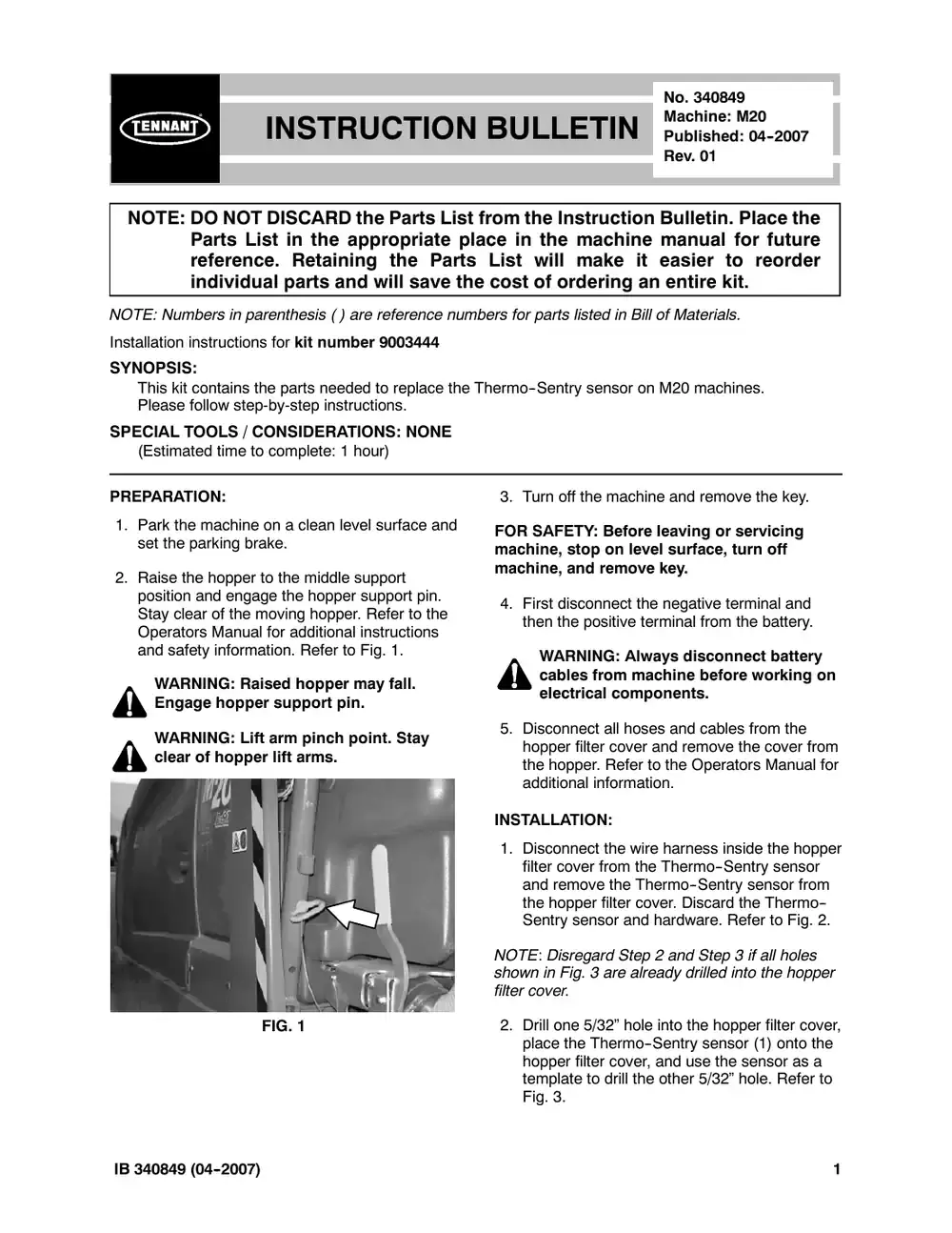
Tennant M20 instruction bulletin 340849, page 1 of 4
Page 1 of 4 SES ref PF-7NWC-O4FS‌‌​⁠‍‍‌​‌​‍‌⁠‌⁠​⁠‌‌⁠‍​​​⁠⁠‍​​​​‌​‍‌​⁠⁠​‍​‍‍​​​⁠⁠​‌​‌​‍⁠‌​⁠​⁠
Text of this page
INSTRUCTION NOTE: DO NOT DISCARD the Parts List Parts List in the appropriate pla reference. Retaining the Parts individual parts and will save the NOTE: Numbers in parenthesis ( ) are reference num Installation instructions for kit number TN4016728 SYNOPSIS: This kit contains the parts needed to replace the T Please follow step-by-step instructions. SPECIAL TOOLS / CONSIDERATIONS: NONE (Estimated time to complete: 1 hour) PREPARATION: 1. Park the machine on a clean level surface and set the parking brake. 2. Raise the hopper to the middle support position and engage the hopper support pin. Stay clear of the moving hopper. Refer to the Operators Manual for additional instructions and safety information. Refer to Fig. 1. WARNING: Raised hopper may fall. Engage hopper support pin. WARNING: Lift arm pinch point. Stay clear of hopper lift arms. FIG. 1 IB 340849 (04--2007) No. 340849 Machine: M20 N BULLETIN Published: 04--2007 Rev. 01 from the Instruction Bulletin. Place the ace in the machine manual for future s List will make it easier to reorder e cost of ordering an entire kit. mbers for parts listed in Bill of Materials. Thermo--Sentry sensor on M20 machines. 3. Turn off the machine and remove the key. FOR SAFETY: Before leaving or servicing machine, stop on level surface, turn off machine, and remove key. 4. First disconnect the negative terminal and then the positive terminal from the battery. WARNING: Always disconnect battery cables from machine before working on electrical components. 5. Disconnect all hoses and cables from the hopper filter cover and remove the cover from the hopper. Refer to the Operators Manual for additional information. INSTALLATION: 1. Disconnect the wire harness inside the hopper filter cover from the Thermo--Sentry sensor and remove the Thermo--Sentry sensor from the hopper filter cover. Discard the Thermo-- Sentry sensor and hardware. Refer to Fig. 2. NOTE: Disregard Step 2 and Step 3 if all holes shown in Fig. 3 are already drilled into the hopper filter cover. 2. Drill one 5/32” hole into the hopper filter cover, place the Thermo--Sentry sensor (1) onto the hopper filter cover, and use the sensor as a template to drill the other 5/32” hole. Refer to Fig. 3. 1
Tennant M20 instruction bulletin 340849, page 2 of 4
Page 2 of 4
Text of this page
FRONT Remove and discard old Thermo--Sentry sensorandmounting hardware FIG. 2 29/32” 3” Reference Existing holes FRONT 3 15/16” Drill new holes 2X ∅ 5/32” 5/16” Drill new hole 1X ∅ 3/8” 3/4” FIG. 3 2 IB 340849 (04--2007)
Tennant M20 instruction bulletin 340849, page 3 of 4
Page 3 of 4
Text of this page
3. Drill a 3/8” hole into the hopper filter cover. Refer to Fig. 3. 4. Use two pan screws (2), two flat washers (3), two lock washers (4), and two hex nuts (5) to install the new Thermo--Sentry sensor (1) onto the hopper filter cover. Refer to Fig. 4. 5. Connect the wire harness inside the hopper filter cover to the Thermo--Sentry sensor (1). Refer to Fig. 4. 6. Route the wires from the Thermo--Sentry sensor (1) past the 3/8” hole in the upper filter cover and use a cable tie (6) to secure the wires to the cover. Refer to Fig. 4. 6 FRONT 3 4 5 FIG IB 340849 (04--2007) 7. Reinstall the hopper filter cover onto the hopper and reconnect all previously disconnected hoses and cables. Refer to the Operators Manual for instructions how to reinstall the hopper filter cover. 8. Reconnect the battery cables to the batteries. Reconnect the positive terminal first and then the negative terminal. 9. Remove the hopper support pin, start the machine, and lower the hopper. Stay clear of the moving hopper. Refer to the Operators Manual for additional instructions and safety information. WARNING: Lift arm pinch point. Stay clear of hopper lift arms. Hopper Filter Cover 2 1 G. 4 3
Tennant M20 instruction bulletin 340849, page 4 of 4
Page 4 of 4
Text of this page
Bill of Materials for Sensor Kit, Repair, Thermo--Sentry [M20]--TN4016728 Tennant Ref. Part No. Description Qty. o TN4016728 ) Sensor Kit, Repair, Thermo--Sentry [M20] 1 Y 1 TN4045538 Switch, Temp [160F] 1 Y 2 TN4041015 Screw, Pan, M3 X 0.50 X 20, 4.8 2 Y 3 TN4042242 Washer, Flat, #06 2 Y 4 TN4034651 Washer, Lock, Int, #06 2 Y 5 TN4042963 ) Nut, Hex, Std, M3 X .050, 8 2 Y 6 TN4011910 Tie, Cable, Nyl, 15.3L W 4.5 Max D 1 TENNANT COMPANY P. O. Box 1452 Minneapolis, MN 55440-1452 4 IB 340849 (04--2007)

Seal Kit, Cover, Front

Tennant instruction bulletin 340848 rev. 00Published 03-2007Kit 9003442

What it’s for: Install the front cover seal kit onto M20/T20 machines.

  • Machines: M20, T20
  • M20: all
  • Power: gasoline, LPG and diesel

Time: 1 hour · Special tools: NONE

Safety warnings (from the bulletin, word for word)

  • FOR SAFETY: Before leaving or servicing machine, stop on level surface, turn off machine, and remove key.

Parts

Parts for Tennant instruction bulletin 340848
ItemPart numberQtyDescriptionPrice
TN4203071Old # 90034421Seal Kit, Cover, FrontKitCall for availability 800-440-6723
1TN4031371Old # 10296521Plate, Mtg, Seal$25.20/EA
2TN4194633Old # 10295451Plate, Mtg, Seal$33.94/EA
3TN4029531Old # 36094310Screw, Pan, #10--14 X 0.75, F/PlstcCall for availability 800-440-6723
4TN1031543Old # 10315431Seal, Aftmkt, Sponge, 0.88 1.00W 08ftCall for availability 800-440-6723

Bulletin PDF: Sign in to view or downloadSign in to download

Installation instructions (2 pages)
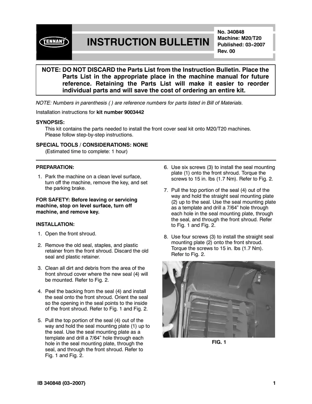
Tennant M20 instruction bulletin 340848, page 1 of 2
Page 1 of 2 SES ref PF-6XV4-YUGZ‌‌​⁠‍‍‌​‌​‍‌⁠‌⁠​⁠‌‌⁠‍⁠​​‌‍⁠‍​​​‌​‍‌​‍‌‍⁠​⁠​​‌⁠‍‌​​⁠​‍‌‌‌​​⁠​
Text of this page
INSTRUCTION NOTE: DO NOT DISCARD the Parts List Parts List in the appropriate pla reference. Retaining the Parts individual parts and will save the NOTE: Numbers in parenthesis ( ) are reference num Installation instructions for kit number TN4203071 SYNOPSIS: This kit contains the parts needed to install the fro Please follow step-by-step instructions. SPECIAL TOOLS / CONSIDERATIONS: NONE (Estimated time to complete: 1 hour) PREPARATION: 1. Park the machine on a clean level surface, turn off the machine, remove the key, and set the parking brake. FOR SAFETY: Before leaving or servicing machine, stop on level surface, turn off machine, and remove key. INSTALLATION: 1. Open the front shroud. 2. Remove the old seal, staples, and plastic retainer from the front shroud. Discard the old seal and plastic retainer. 3. Clean all dirt and debris from the area of the front shroud cover where the new seal (4) will be mounted. Refer to Fig. 2. 4. Peel the backing from the seal (4) and install the seal onto the front shroud. Orient the seal so the opening in the seal points to the inside of the front shroud. Refer to Fig. 1 and Fig. 2. 5. Pull the top portion of the seal (4) out of the way and hold the seal mounting plate (1) up to the seal. Use the seal mounting plate as a template and drill a 7/64” hole through each hole in the seal mounting plate, through the seal, and through the front shroud. Refer to Fig. 1 and Fig. 2. IB 340848 (03--2007) No. 340848 Machine: M20/T20 N BULLETIN Published: 03--2007 Rev. 00 from the Instruction Bulletin. Place the ace in the machine manual for future s List will make it easier to reorder e cost of ordering an entire kit. mbers for parts listed in Bill of Materials. ont cover seal kit onto M20/T20 machines. 6. Use six screws (3) to install the seal mounting plate (1) onto the front shroud. Torque the screws to 15 in. lbs (1.7 Nm). Refer to Fig. 2. 7. Pull the top portion of the seal (4) out of the way and hold the straight seal mounting plate (2) up to the seal. Use the seal mounting plate as a template and drill a 7/64” hole through each hole in the seal mounting plate, through the seal, and through the front shroud. Refer to Fig. 1 and Fig. 2. 8. Use four screws (3) to install the straight seal mounting plate (2) onto the front shroud. Torque the screws to 15 in. lbs (1.7 Nm). Refer to Fig. 2. FIG. 1 1
Tennant M20 instruction bulletin 340848, page 2 of 2
Page 2 of 2
Text of this page
Front Shroud 1 3 Qty 10 4 7/64” holes 2 FIG. 2 Bill of Materials for Seal Kit, Cover, Front--TN4203071 Tennant Ref. Part No. Description Qty. o TN4203071 ) Seal Kit, Cover, Front 1 Y 1 TN4031371 Plate, Mtg, Seal 1 Y 2 TN4194633 Plate, Mtg, Seal 1 Y 3 TN4029531 Screw, Pan, #10--14 X 0.75, F/Plstc 10 Y 4 TN1031543 Seal, Aftmkt, Sponge, 0.88 1.00W 08ft 1 TENNANT COMPANY P. O. Box 1452 Minneapolis, MN 55440-1452 2 IB 340848 (03--2007)

Switch Kit, Float, Repair

Tennant instruction bulletin 340850 rev. 00Published 03-2007Kit 9003449

What it’s for: Replace the float switch protector bracket on M20 machines.

  • Machines: M20
  • M20: all
  • Power: gasoline, LPG and diesel

Time: 1 hour · Special tools: NONE

Safety warnings (from the bulletin, word for word)

  • FOR SAFETY: Before leaving or servicing machine, stop on level surface, turn off machine, engage the parking brake, and remove key.

Parts

Parts for Tennant instruction bulletin 340850
ItemPart numberQtyDescriptionPrice
TN4016730Old # 90034491Switch Kit, Float, RepairKit$114.00/EA
1TN4027617Old # 764262Washer, Sealing, 0.28B 0.75D SS, Neo$3.50/EA
2TN4041942Old # 090072Screw, Hex, M6 X 1.0 X 25, SS$3.30/EA
3TN4041928Old # 087122Nut, Hex, Lock, M6 X 1.00, SS, NL$2.50/EA
4TN4043530Old # 10378161Bracket, Protector, Float Switch$43.60/EA

Bulletin PDF: Sign in to view or downloadSign in to download

Installation instructions (3 pages)
Tennant M20 instruction bulletin 340850, page 1 of 3
Page 1 of 3 SES ref PF-R6W5-CYGM‌‌​⁠‍‍‌​‌​‍‌⁠‌⁠​⁠‌‌⁠​​‍‌​‌⁠‌​​​‌​‍‌​‌⁠‍‍‌‌⁠‌​‍​‌​⁠​‍​‌​⁠⁠‍⁠​
Text of this page
INSTRUCTION NOTE: DO NOT DISCARD the Parts List Parts List in the appropriate pla reference. Retaining the Parts individual parts and will save the NOTE: Numbers in parenthesis ( ) are reference num Installation instructions for kit number TN4016730 SYNOPSIS: This kit contains the parts needed to replace the f Please follow step-by-step instructions. SPECIAL TOOLS / CONSIDERATIONS: NONE (Estimated time to complete: 1 hour) PREPARATION: 1. Park the machine on a clean level surface, turn off the machine, engage the parking brake, and remove the key. FOR SAFETY: Before leaving or servicing machine, stop on level surface, turn off machine, engage the parking brake, and remove key. 2. Empty the recovery tank. Refer to the Operators manual for instructions how to empty the recovery tank. 3. Lift and lock the recovery tank cover completely open. IB 340850 (03--2007) No. 340850 Machine: M20 N BULLETIN Published: 03--2007 Rev. 00 from the Instruction Bulletin. Place the ace in the machine manual for future s List will make it easier to reorder e cost of ordering an entire kit. mbers for parts listed in Bill of Materials. float switch protector bracket on M20 machines. INSTALLATION: 1. Remove the hardware holding the float switch and float switch protector bracket to the recovery tank. Set the hardware aside. Refer to Fig. 3. 2. Remove the existing float switch protector bracket (part number 1019285) from the recovery tank. Discard the protector bracket. Refer to Fig. 3. 3. Reinstall the hardware onto the float switch. Refer to Fig. 3. 4. Drill two holes through the recovery tank. Refer to Fig. 4 for sizes/locations of holes. 5. Remove/smooth all burrs and/or ridges from around the two holes drilled into the recovery tank in the previous step. Refer to Fig. 4. 1
Tennant M20 instruction bulletin 340850, page 2 of 3
Page 2 of 3
Text of this page
6. Use two hex screws (2), two sealing washers (1), and two hex nuts (3) to install the new (1), and two hex nuts (3) to install the new float switch protector bracket (4) in the recovery tank. Note location of sealing washers (1) outside the recovery tank. Refer to Fig. 1 and Fig. 2. 1 2 FIG. 1 FIG 2 3 4 Float Switch FIG. 2 7. Start and use machine to scrub floors. Ensure float switch operates when the recovery tank is full. Remove old float switch protector bracket (1019285) from recovery tank. Discard the old protector bracket. Replace with new float switch protector bracket (4). Remove hardware holding the float switch onto the recovery tank. Reinstall hardware onto float switch after removing the old floatswitch protectorbracket. G. 3 IB 340850 (03--2007)
Tennant M20 instruction bulletin 340850, page 3 of 3
Page 3 of 3
Text of this page
FIG Bill of Materials for Switch Tennant Ref. Part No. Description o TN4016730 ) Switch Kit, Float, Repair Y 1 TN4027617 Washer, Sealing, 0.28B 0 Y 2 TN4041942 Screw, Hex, M6 X 1.0 X 2 Y 3 TN4041928 Nut, Hex, Lock, M6 X 1.0 Y 4 TN4043530 Bracket, Protector, Float TENNANT P. O. Bo Minneapolis, M IB 340850 (03--2007) * * Be sure to remove / smooth all burrs and / or ridges from around the holes drilled into the recovery tank G. 4 Kit, Float, Repair--TN4016730 Qty. 1 0.75D SS, Neo 2 25, SS 2 00, SS, NL 2 Switch 1 COMPANY ox 1452 MN 55440-1452 3

A/V Kit, Flsh, CI [M20/T20]

Tennant instruction bulletin 340856 rev. 00Published 03-2007Kit 9003487

What it’s for: Install a flashing light/alarm kit on M20 and T20 machines.

  • Machines: M20, T20
  • M20: all
  • Power: gasoline, LPG and diesel
  • Applies to: overhead guard, lights

Time: 1.5 hours · Special tools: NONE

Safety warnings (from the bulletin, word for word)

  • FOR SAFETY: Before leaving or servicing machine, stop on level surface, set parking brake, turn off machine, and remove key.
  • WARNING: Always disconnect battery cables from machine before working on electrical components. NOTE: If installing the flashing light (13) onto the bracket (5), proceed to the instructions beginning on this page. If installing the flashing light (13) onto the overhead guard, proceed to the instructions starting on page 6.

Parts

Parts for Tennant instruction bulletin 340856
ItemPart numberQtyDescriptionPrice
TN4016753Old # 90034871A/V Kit, Flsh, CI [M20/T20]KitCall for availability 800-440-6723
1TN4011838Old # 619201Alarm Assy, Backup, 12--24vdc 82--107dbaCall for availability 800-440-6723
2TN4035367Old # 241964Screw, Pan, M5 X 0.8 X 20, SS$3.20/EA
3TN4042244Old # 190664Washer, Flat, #10$2.50/EA
4TN4041991Old # 097394Nut, Hex, Lock, M5 X 0.80, NL, SS$3.30/EA
5TN4035919Old # 10194451Bracket, Sppt, Revl Light$55.20/EA
6TN4041992Old # 097404Screw, Hex, M8 X 1.25 X 20, SS$3.30/EA
7TN4035242Old # 10172184Washer, Flat, 0.32b 1.00d .12, SS$3.40/EA
8TN4036226Old # 10199711Harness, Warning / Backup [M20 & T20]$27.50/EA
9TN4036203Old # 10196471Harness, Warning / OHG [M20]$23.56/EA
11TN4014138Old # 492662Tie, Cable, Nyl, 07.3L .19W 1.8 Max D$2.50/EA
12TN4011909Old # 7631154Tie, Cable, 6.0L, 1.25D Max$2.30/EA
13TN1017248Old # 10172481Light, Flsh, Amb, 12--48VDCCall for availability 800-440-6723
14TN4013452Old # 462362Clamp, Cable, Stl, 0.26D X 0.56W, 1 Hole$3.60/EA

Bulletin PDF: Sign in to view or downloadSign in to download

Installation instructions (12 pages)
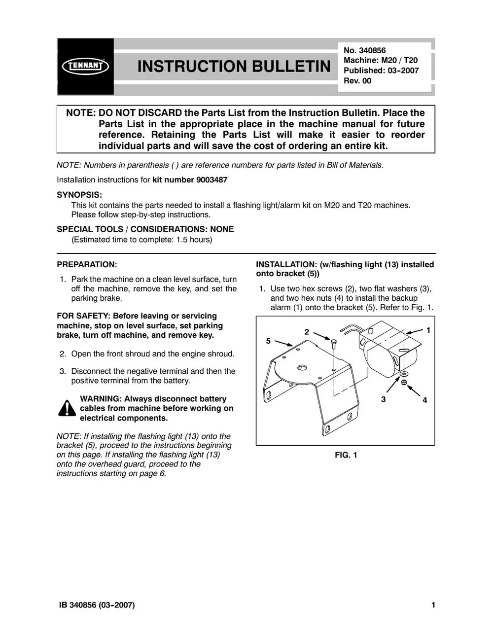
Tennant M20 instruction bulletin 340856, page 1 of 12
Page 1 of 12 SES ref PF-IKCU-Y7CS‌‌​⁠‍‍‌​‌​‍‌⁠‌⁠​⁠‌‌⁠‍‍⁠​​‍‍​​​​‌​‍‌​​‍​​‌​‍​‌‍⁠​​⁠⁠⁠‍​⁠​​‍⁠‍
Text of this page
INSTRUCTION NOTE: DO NOT DISCARD the Parts List Parts List in the appropriate pla reference. Retaining the Parts individual parts and will save the NOTE: Numbers in parenthesis ( ) are reference num Installation instructions for kit number TN4016753 SYNOPSIS: This kit contains the parts needed to install a flash Please follow step-by-step instructions. SPECIAL TOOLS / CONSIDERATIONS: NONE (Estimated time to complete: 1.5 hours) PREPARATION: 1. Park the machine on a clean level surface, turn off the machine, remove the key, and set the parking brake. FOR SAFETY: Before leaving or servicing machine, stop on level surface, set parking brake, turn off machine, and remove key. 2. Open the front shroud and the engine shroud. 3. Disconnect the negative terminal and then the positive terminal from the battery. WARNING: Always disconnect battery cables from machine before working on electrical components. NOTE: If installing the flashing light (13) onto the bracket (5), proceed to the instructions beginning on this page. If installing the flashing light (13) onto the overhead guard, proceed to the instructions starting on page 6. IB 340856 (03--2007) No. 340856 Machine: M20 / T20 N BULLETIN Published: 03--2007 Rev. 00 from the Instruction Bulletin. Place the ace in the machine manual for future s List will make it easier to reorder e cost of ordering an entire kit. mbers for parts listed in Bill of Materials. hing light/alarm kit on M20 and T20 machines. INSTALLATION: (w/flashing light (13) installed onto bracket (5)) 1. Use two hex screws (2), two flat washers (3), and two hex nuts (4) to install the backup alarm (1) onto the bracket (5). Refer to Fig. 1. 2 1 5 3 4 FIG. 1 1
Tennant M20 instruction bulletin 340856, page 2 of 12
Page 2 of 12
Text of this page
2. Route the wires from the flashing light (13) down through the hole in the light support bracket (5) and use a hex screw (2), flat washer (3), and hex nut (4) to install the light onto the bracket. Refer to Fig. 2. 2 13 5 3 4 FIG. 2 3. Route the wires from the flashing light (13) through a cable clamp (9) and use a hex screw (2), two flat washers (3), and hex nut (4) to install the cable clamp underneath the lamp support bracket (5) and completely secure the light to the bracket. Refer to Fig. 3. 2 13 3 5 3 14 4 FIG. 3 2 4. Open the recovery tank cover and pull the main wire harness backup alarm and revolving light connector from between the recovery and solution tank. Connect the warning/backup harness (8) to the main wire harness. Refer to Fig. 4 or Fig. 5, and Fig. 8. FIG. 4 -- M20 Harness Location FIG. 5 -- T20 Harness Location 5. Route the warning/backup harness (8) through the notch in the solution tank and install a cable clamp (9) onto the harness. Refer to Fig. 8. IB 340856 (03--2007)
Tennant M20 instruction bulletin 340856, page 3 of 12
Page 3 of 12
Text of this page
6. Use three hex screws (6) and three flat washers (7) to install the bracket (5) onto the back of the machine. Refer to Fig. 6. 5 7 6 FIG. 6 7. Use a hex screw (6) and flat washer (7) to install the cable clamp (9) on the warning/ backup harness (8) onto light support bracket (5) and solution tank. Refer to Fig. 7. 5 9 6 7 FIG. 7 IB 340856 (03--2007) 8. Connect the wires from the backup alarm (1) and the flashing light (13) to the warning/ backup harness (8). Refer to Fig. 4. 9. Route excess cable from the main wire harness and the warning/backup harness (8) back down between the recovery and solution tank. Refer to Fig. 3 and Fig. 4. 10. Reconnect the positive terminal and then the negative terminal to the battery. 11. Start the machine and move the machine in reverse. The backup alarm should sound while machine is moving in reverse. The light should flash while the engine is operating. 3
Tennant M20 instruction bulletin 340856, page 4 of 12
Page 4 of 12
Text of this page
2 Note: Following items are not used when flashing light (13) is installed onto support bracket (5): (9) TN4036203 Overhead Guard Warning Harness--Qty 1 (10) 10632--17 Rubber Grommet--Qty 4 (11) TN4014138 7.3” Nylon Cable Tie--Qty 2 13 (12) TN4011909 6” Nylon Cable Tie--Qty 4 2 1 3 4 5 8 3 4 6 7 14 14 3 4 FIG. 8 4 IB 340856 (03--2007)
Tennant M20 instruction bulletin 340856, page 5 of 12
Page 5 of 12
Text of this page
Backup / Warning Harness (9) Main Wire Harness FIG. 9 IB 340856 (03--2007) 5
Tennant M20 instruction bulletin 340856, page 6 of 12
Page 6 of 12
Text of this page
INSTALLATION: (w/flashing light (13) installed onto overhead guard) 1. Pull the insulation away from the operator compartment panel and drill a 13/16” hole into the panel. If there is already a hole in the panel, remove the plug from the hole. Refer to Fig. 1 and Fig. 2. FIG. 1 48.08 20.89 [1.893] [0.822] 59.90 [2.358] FIG. 2 6 2. Insert a grommet (10) into the hole in the operator compartment panel and the hole on top the overhead guard. Refer to Fig. 3 and Fig. 4. FIG. 3 4 3 13 10 2 FIG. 4 3. Route the wires from the flashing light (13) down through the grommet (10) installed in the overhead guard and use two hex screws (2), two flat washers (3), and two hex nuts (4) to install the light onto the overhead guard. Refer to Fig. 4. 4. Connect the warning/overhead harness (9) to the main wire harness, route the warning/ overhead harness through the grommet (10) installed in the operator compartment panel, up along leg of the overhead guard, and to the rear cross member of the overhead guard. Refer to Fig. 9 and Fig. 10. IB 340856 (03--2007)
Tennant M20 instruction bulletin 340856, page 7 of 12
Page 7 of 12
Text of this page
5. Insert a grommet (10) into the rear hole in the rear cross member of the overhead guard and route the warning/overhead harness (9) through the grommet and the front hole in the rear cross member. Refer to Fig. 5. Install first, before routing warning/ overhead harness (9) through cross member 10 10 Install after routing warning/ overhead harness (9) through cross member FIG. 5 6. Slide the remaining grommet (10) onto the warning/overhead harness (9) and insert the grommet into the front hole in the rear cross member of the overhead guard. Refer to Fig. 5. 7. Route the warning/OHG harness (9) through the notch in the overhead guard insulation and connect the harness to the flashing light (13). Refer to Fig. 6 and Fig. 10. FIG. 6 IB 340856 (03--2007) 8. Use four cable ties (12) to secure the warning/ overhead harness (9) to the leg of the overhead guard. Refer to Fig. 7 and Fig. 8. FIG. 7 FIG. 8 9. Use two cable ties (11) to secure the warning/ overhead harness (9) to the top of the overhead guard. Refer to Fig. 12. 10. Use two hex screws (2), two flat washers (3), and two hex nuts (4) to install the backup alarm (1) onto the bracket (5). Refer to Fig. 9. 2 1 5 3 4 FIG. 9 7
Tennant M20 instruction bulletin 340856, page 8 of 12
Page 8 of 12
Text of this page
11. Open the recovery tank cover and pull the main wire harness backup alarm connector from between the recovery and solution tank. Connect the warning/backup harness (8) to the main wire harness. Refer to Fig. 10 or Fig. 11, and Fig. 14. FIG. 10 -- M20 Harness Location FIG. 11 -- T20 Harness Location 12. Route the warning/backup harness (8) through the notch in the solution tank and install a cable clamp (9) onto the harness. Refer to Fig. 8. 8 13. Connect the wires from the backup alarm (1) to the warning/ backup harness (8). Refer to Fig. 14. 14. Neatly bundle the flashing light wires on the warning/ backup harness (8) and secure them to the harness with either cable ties of electrical tape. 15. Route excess cable from the main wire harness and the warning/backup harness (8) back down between the recovery and solution tank. Refer to Fig. 3 and Fig. 4. 16. Reconnect the negative battery cable and then the positive terminal to the battery. 17. Start the machine and move the machine in reverse. The backup alarm should sound while machine is moving in reverse. The light should flash while the engine is operating. IB 340856 (03--2007)
Tennant M20 instruction bulletin 340856, page 9 of 12
Page 9 of 12
Text of this page
4 3 13 13 10 2 Connect to wires from revolving light (13) FRONT Locations for cable ties (11) securing warning/overhead harnes (9) to top of overhead guard REAR FIG IB 340856 (03--2007) REAR 12 Refer to Fig. 7 and Fig. 8 for locations of wire ties (12) on leg of overhead guard 9 10 Connect to main wire harness ss G. 12 9
Tennant M20 instruction bulletin 340856, page 10 of 12
Page 10 of 12
Text of this page
Main Wire Harness Warning/OHG Harness (9) FIG. 13 10 IB 340856 (03--2007)
Tennant M20 instruction bulletin 340856, page 11 of 12
Page 11 of 12
Text of this page
Backup / Warning Harness (9) Main Wire Harness FIG. 14 IB 340856 (03--2007) 11
Tennant M20 instruction bulletin 340856, page 12 of 12
Page 12 of 12
Text of this page
Bill of Materials for A/V Kit, Flsh, CI [M20/T20]--TN4016753 Tennant Ref. Part No. Description Qty. o TN4016753 A/V Kit, Flsh, CI [M20/T20] 1 Y 1 TN4011838 Alarm Assy, Backup, 12--24vdc 82--107dba 1 Y 2 TN4035367 Screw, Pan, M5 X 0.8 X 20, SS 4 Y 3 TN4042244 Washer, Flat, #10 4 Y 4 TN4041991 Nut, Hex, Lock, M5 X 0.80, NL, SS 4 Y 5 TN4035919 Bracket, Sppt, Revl Light 1 Y 6 TN4041992 Screw, Hex, M8 X 1.25 X 20, SS 4 Y 7 TN4035242 Washer, Flat, 0.32b 1.00d .12, SS 4 Y 8 TN4036226 Harness, Warning / Backup [M20 & T20] 1 Y 9 TN4036203 Harness, Warning / OHG [M20] 1 Y 10 10632--17 Grommet, Rbr, 0.50ID, F/0.8H, .12 Matl 4 Y 11 TN4014138 Tie, Cable, Nyl, 07.3L .19W 1.8 Max D 2 Y 12 TN4011909 Tie, Cable, 6.0L, 1.25D Max 4 Y 13 TN1017248 Light, Flsh, Amb, 12--48VDC 1 Y 14 TN4013452 Clamp, Cable, Stl, 0.26D X 0.56W, 1 Hole 2 TENNANT COMPANY P. O. Box 1452 Minneapolis, MN 55440-1452 12 IB 340856 (03--2007)

Lift Kit, Sqge, Replmt

Tennant instruction bulletin 340855 rev. 00Published 04-2007Kit 9003478

What it’s for: Install a squeegee lift replacement kit on M20/T20 machines.

  • Machines: M20, T20
  • M20: all
  • Power: gasoline, LPG and diesel

Time: 1.5 hours · Special tools: NONE

Safety warnings (from the bulletin, word for word)

  • FOR SAFETY: Before leaving or servicing machine, stop on a level surface, set parking brake, turn off machine, and remove key.

Parts

Parts for Tennant instruction bulletin 340855
ItemPart numberQtyDescriptionPrice
TN4016746Old # 90034781Lift Kit, Sqge, ReplmtKitCall for availability 800-440-6723
1TN4190906Old # 10381921Angle, Lift, SqgeCall for availability 800-440-6723
2TN4042902Old # 016856Washer, Flat, 0.38B 0.88D .08, SS$2.60/EA
3TN4041929Old # 087133Nut, Hex, Lock, M8 X 1.25, NL, SS$3.30/EA
4TN4040607Old # 2225052Screw, Hex, M8 X 1.25 X 45, SS$4.00/EA
5TN4041282Old # 069571Screw, Hex, M8 X 1.25 X 60, 8.8$3.40/EA

Bulletin PDF: Sign in to view or downloadSign in to download

Installation instructions (4 pages)
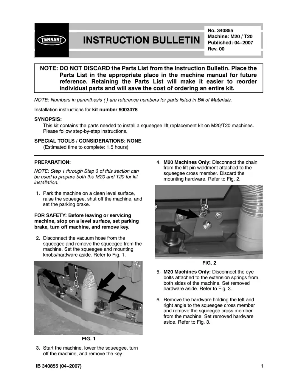
Tennant M20 instruction bulletin 340855, page 1 of 4
Page 1 of 4 SES ref PF-2OGR-ACMB‌‌​⁠‍‍‌​‌​‍‌⁠‌⁠​⁠‌‌⁠⁠⁠⁠‌‍‌​‍​​​‌​‍‌​‍‌⁠​‌‌‍‍⁠‍⁠‍⁠​‌‍‍‍‍‍​⁠‍‌
Text of this page
INSTRUCTION NOTE: DO NOT DISCARD the Parts List Parts List in the appropriate pla reference. Retaining the Parts individual parts and will save the NOTE: Numbers in parenthesis ( ) are reference num Installation instructions for kit number TN4016746 SYNOPSIS: This kit contains the parts needed to install a sque Please follow step-by-step instructions. SPECIAL TOOLS / CONSIDERATIONS: NONE (Estimated time to complete: 1.5 hours) PREPARATION: NOTE: Step 1 through Step 3 of this section can be used to prepare both the M20 and T20 for kit installation. 1. Park the machine on a clean level surface, raise the squeegee, shut off the machine, and set the parking brake. FOR SAFETY: Before leaving or servicing machine, stop on a level surface, set parking brake, turn off machine, and remove key. 2. Disconnect the vacuum hose from the squeegee and remove the squeegee from the machine. Set the squeegee and mounting knobs/hardware aside. Refer to Fig. 1. FIG. 1 3. Start the machine, lower the squeegee, turn off the machine, and remove the key. IB 340855 (04--2007) No. 340855 Machine: M20 / T20 N BULLETIN Published: 04--2007 Rev. 00 from the Instruction Bulletin. Place the ace in the machine manual for future s List will make it easier to reorder e cost of ordering an entire kit. mbers for parts listed in Bill of Materials. eegee lift replacement kit on M20/T20 machines. 4. M20 Machines Only: Disconnect the chain from the lift pin weldment attached to the squeegee cross member. Discard the mounting hardware. Refer to Fig. 2. FIG. 2 5. M20 Machines Only: Disconnect the eye bolts attached to the extension springs from both sides of the machine. Set removed hardware aside. Refer to Fig. 3. 6. Remove the hardware holding the left and right angle to the squeegee cross member and remove the squeegee cross member from the machine. Set removed hardware aside. Refer to Fig. 3. 1
Tennant M20 instruction bulletin 340855, page 2 of 4
Page 2 of 4
Text of this page
Note: Only p Remove iden Squeegee Cross Member Left Eye Bolt Left Links Left Angle Left Extension Spring FIG INSTALLATION: 1. Remove the lift pin weldment from the squeegee cross member. Discard the lift pin weldment and all hardware. Refer to Fig. 4. 2 arts on the left side of machine are shown. ntical parts from right side of machine. Remove and set hardware holding eye bolt to squeegee cross member aside (M20 Only) Remove and set hardware holding left angle to squeegee cross member G. 3 Remove and discard lift pin weldment 1034147, or 1025706, and all hardware used to secure lift pin weldment to squeegee cross member. DO NOT remove any other parts from squeegee cross member. Squeegee Cross Member FIG. 4 IB 340855 (04--2007)
Tennant M20 instruction bulletin 340855, page 3 of 4
Page 3 of 4
Text of this page
2. Place the new squeegee lift angle (1) onto the side the squeegee cross member opposite of where the lift angle is mounted align the outer holes in the lift angle with the holes in the squeegee cross member, and use the lift angle as a template to drill a 3/8” hole through the center hole in the lift angle and through the squeegee cross member. Refer to Fig 5. 3. Use two hex screws (4), four flat washers (2), and two hex nuts (3) to install the squeegee lift angle (1) onto the squeegee cross member. Refer to Fig. 5. 4. M20 Machines Only (These parts can be discarded if installing kit on a T20 machine): Slide a flat washer (2) onto the hex screw (5) and insert the hex screw through the new hole and the existing hole in the squeegee cross member and the squeegee lift angle (1). Refer to Fig. 5. Squeegee Cross Member Existing hole, drill 3/8” hole on other side New 3/8” h Existing ho 3 2 2 4 1 2 (M20 Only) 2 4 3 (M20 Only) FIG IB 340855 (04--2007) 5. Reinstall the squeegee cross member onto the machine. If working on an M20 machine, be sure the hex screw (5) and flat washer (2) installed in the previous step remain in place in the squeegee cross member and squeegee lift angle (1). Refer to Fig. 3 and Fig. 5. 6. M20 Machines Only (These parts can be discarded if installing kit on a T20 machine. The T20 is not equipped with this chain): Use a flat washer (2) and hex nut (3) to attach the chain to the hex screw (5). Refer to Fig. 2 and Fig. 5. 7. Reinstall the squeegee onto the machine. Refer to Fig. 1 Use squeegee lift angle (1) as template to drill new 3/8” into opposite side of existing hole hole ole 2 (M20 Only) Chain is attached 3 5 to hex screw (5) (M20 Only) 3 2 Squeegee Cross Member G. 5 3
Tennant M20 instruction bulletin 340855, page 4 of 4
Page 4 of 4
Text of this page
8. Level the rear squeegee and check/adjust the rear squeegee blade deflection. Refer to LEVELING THE REAR SQUEEGEE and ADJUSTING THE REAR SQUEEGEE BLADE DEFLECTION in the Maintenance section of the Operators manual for instructions how to level the rear squeegee and adjust rear squeegee blade deflection. 9. Operate the machine and check the squeegee level and squeegee blade deflection. Make adjustments as necessary. Bill of Materials for Lift Ki Tennant Ref. Part No. Description o TN4016746 ) Lift Kit, Sqge, Replmt Y 1 TN4190906 Angle, Lift, Sqge Y 2 TN4042902 Washer, Flat, 0.38B 0.88 Y 3 TN4041929 Nut, Hex, Lock, M8 X 1.2 Y 4 TN4040607 Screw, Hex, M8 X 1.25 X Y 5 TN4041282 ) Screw, Hex, M8 X 1.25 X TENNANT P. O. Bo Minneapolis, M 4 it, Sqge, Replmt--TN4016746 Qty. 1 1 8D .08, SS 6 25, NL, SS 3 X 45, SS 2 X 60, 8.8 1 COMPANY ox 1452 MN 55440-1452 IB 340855 (04--2007)

OHG Harness (5) FIG. 11 Bill of Materials for Light Kit, Flsh, W/OHG, CI [M20 and T20]

Tennant instruction bulletin 340820 rev. 02Published 03-2007Kit 9001718

What it’s for: Install an OHG flashing light kit on M20/T20 machines.

  • Machines: M20, T20
  • M20: all
  • Power: gasoline, LPG and diesel
  • Applies to: overhead guard, lights

Time: 1 hour · Special tools: NONE

Safety warnings (from the bulletin, word for word)

  • FOR SAFETY: Before leaving or servicing machine, stop on level surface, set parking brake, turn off machine, and remove key.
  • WARNING: Always disconnect battery cables from machine before working on electrical components.

Parts

Parts for Tennant instruction bulletin 340820
ItemPart numberQtyDescriptionPrice
TN4019724Old # 90017181OHG Harness (5) FIG. 11 Bill of Materials for Light Kit, Flsh, W/OHG, CI [M20 and T20]Kit$372.90/EA
1TN1017248Old # 10172481Light, Flsh, Amb, 12--48VDCCall for availability 800-440-6723
2TN4035367Old # 241962Screw, Pan, M5 X 0.8 X 20, SS$3.20/EA
3TN4042244Old # 190662Washer, Flat, #10$2.50/EA
4TN4041991Old # 097392Nut, Hex, Lock, M5 X 0.80, NL, SS$3.30/EA
5TN4036203Old # 10196471Harness, Warning / OHG [M20]$23.56/EA
7TN4011909Old # 7631154Tie, Cable, 6.0L, 1.25D Max$2.30/EA
8TN4014138Old # 492662Tie, Cable, Nyl, 07.3L .19W 1.8 Max D$2.50/EA

Bulletin PDF: Sign in to view or downloadSign in to download

Installation instructions (5 pages)
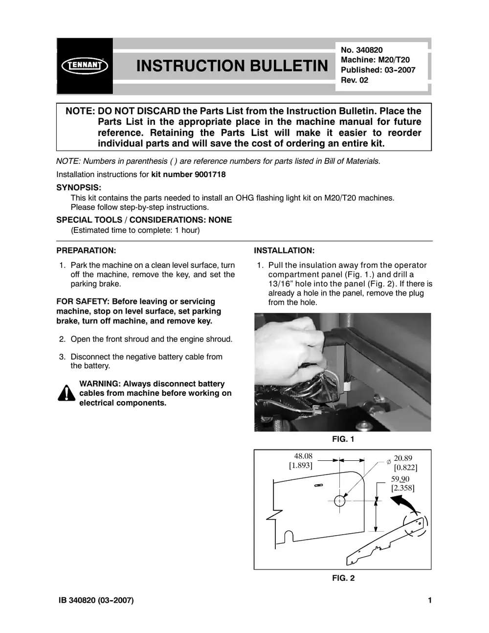
Tennant M20 instruction bulletin 340820, page 1 of 5
Page 1 of 5 SES ref PF-Z6DJ-NCRS‌‌​⁠‍‍‌​‌​‍‌⁠‌⁠​⁠‌‌⁠‍‌⁠⁠⁠‌‍‍​​​‌​‍‌​‌‌​⁠⁠‍⁠​‍‍‍⁠⁠​‌‍​‍​​‍⁠​⁠
Text of this page
INSTRUCTION NOTE: DO NOT DISCARD the Parts List Parts List in the appropriate pla reference. Retaining the Parts individual parts and will save the NOTE: Numbers in parenthesis ( ) are reference num Installation instructions for kit number TN4019724 SYNOPSIS: This kit contains the parts needed to install an OH Please follow step-by-step instructions. SPECIAL TOOLS / CONSIDERATIONS: NONE (Estimated time to complete: 1 hour) PREPARATION: 1. Park the machine on a clean level surface, turn off the machine, remove the key, and set the parking brake. FOR SAFETY: Before leaving or servicing machine, stop on level surface, set parking brake, turn off machine, and remove key. 2. Open the front shroud and the engine shroud. 3. Disconnect the negative battery cable from the battery. WARNING: Always disconnect battery cables from machine before working on electrical components. IB 340820 (03--2007) No. 340820 Machine: M20/T20 N BULLETIN Published: 03--2007 Rev. 02 from the Instruction Bulletin. Place the ace in the machine manual for future s List will make it easier to reorder e cost of ordering an entire kit. mbers for parts listed in Bill of Materials. HG flashing light kit on M20/T20 machines. INSTALLATION: 1. Pull the insulation away from the operator compartment panel (Fig. 1.) and drill a 13/16” hole into the panel (Fig. 2). If there is already a hole in the panel, remove the plug from the hole. FIG. 1 48.08 20.89 [1.893] [0.822] 59.90 [2.358] FIG. 2 1
Tennant M20 instruction bulletin 340820, page 2 of 5
Page 2 of 5
Text of this page
2. Insert a grommet (6) into the hole in the operator compartment panel (Fig. 3) and the hole on top the overhead guard (Fig. 4). FIG. 3 6 FIG. 4 2 3. Route the wires from the light (1) down through the grommet (6) installed in the overhead guard and use two hex screws (2), flat washers (3), and hex nuts (4) to install the light onto the overhead guard. (Fig. 5) 4 3 1 6 2 FIG. 5 4. Connect the warning/overhead harness (5) to the main wire harness, route the warning/ overhead harness through the grommet installed in the operator compartment panel, up along leg of the overhead guard, and to the rear cross member of the overhead guard. (Fig. 10 and Fig. 11) IB 340820 (03--2007)
Tennant M20 instruction bulletin 340820, page 3 of 5
Page 3 of 5
Text of this page
5. Insert a grommet (6) into the rear hole in the rear cross member of the overhead guard and route the warning/overhead harness (5) through the grommet and the front hole in the rear cross member. (Fig. 6) Install first before routing warning/ overheadharness (5) through cross member 6 Install after routing warning/overhead harness (5) through cross member FIG. 6 6. Slide the remaining grommet (6) onto the warning/overhead harness (5) and insert the grommet into the front hole in the rear cross member of the overhead guard. (Fig. 6) 7. Route the warning/OHG harness (5) through the notch in the overhead guard insulation and connect the warning/OHG harness to the light (1). (Fig. 7 and Fig. 11) FIG. 7 IB 340820 (03--2007) 8. Use four cable ties (7) to secure the warning/ overhead harness (5) to the leg of the overhead guard. (Fig. 8 and Fig. 9) FIG. 8 FIG. 9 9.Use two cable ties (8) to secure the warning/ overhead harness (5) to the top of the overhead guard. (Fig. 10) 10. Reconnect the negative battery cable to the battery. 11. Start and test the machine to ensure the overhead guard light operates. 3
Tennant M20 instruction bulletin 340820, page 4 of 5
Page 4 of 5
Text of this page
1 6 2 Connect to wires from revolving light (1) FRONT Locations for cable ties (8) securing warning/overhead harness (5) to top of overhead guard REAR FIG 4 4 3 REAR 7 Refer to Fig. 8 and Fig. 9 for locations of wire ties (7) on overhead guard 5 6 Connect to main wire harness G. 10 IB 340820 (03--2007)
Tennant M20 instruction bulletin 340820, page 5 of 5
Page 5 of 5
Text of this page
Main Wire Harness Warning/OHG Harness (5) FIG. 11 Bill of Materials for Light Kit, Flsh, W/OHG, CI [M20 and T20]--TN4019724 Tennant Ref. Part No. Description Qty. o TN4019724 ) Light Kit, Flsh, W/OHG, CI [M20 and T20] 1 Y 1 TN1017248 Light, Flsh, Amb, 12--48VDC 1 Y 2 TN4035367 Screw, Pan, M5 X 0.8 X 20, SS 2 Y 3 TN4042244 Washer, Flat, #10 2 Y 4 TN4041991 Nut, Hex, Lock, M5 X 0.80, NL, SS 2 Y 5 TN4036203 ) Harness, Warning / OHG [M20] 1 Y 6 10632--17 Grommet, Rbr, 0.50ID, F/0.8H, .12 Matl 4 Y 7 TN4011909 Tie, Cable, 6.0L, 1.25D Max 4 Y 8 TN4014138 Tie, Cable, Nyl, 07.3L .19W 1.8 Max D 2 TENNANT COMPANY P. O. Box 1452 Minneapolis, MN 55440-1452 IB 340820 (03--2007) 5

Wand Kit, Vacuum, CI [M20]

Tennant instruction bulletin 340817 rev. 04Published 04-2008Kit 9001334

What it’s for: Install a vacuum wand kit on M20 machines.

  • Machines: M20
  • M20: all
  • Power: gasoline, LPG and diesel

Time: 1 hour · Special tools: NONE

Safety warnings (from the bulletin, word for word)

  • FOR SAFETY: Before leaving or servicing machine, stop on level surface, turn off machine, set parking brake, and remove key.

Parts

Parts for Tennant instruction bulletin 340817
ItemPart numberQtyDescriptionPrice
TN4019673Old # 90013341Wand Kit, Vacuum, CI [M20]Kit$1,037.30/EA
1TN4017746Old # 655801Bag, Power$159.30/EA
2TN4016302Old # 729684Rivet, Plstc, .250 X 0.898$3.20/EA
3TN4017057Old # 634481Tube, Wand, Vacuum, Metal [1pick=1box]Call for availability 800-440-6723
4TN4018319Old # 696571Hose Assy, W/2cuff, 1.5d 84l [Vacwand]$303.60/EA
5TN4017055Old # 634301Shoe, Plstc, Sqge, 14.0Call for availability 800-440-6723
6TN4017060Old # 634511Nozzle, Wand, Plstc, 14.0lgCall for availability 800-440-6723
7TN4017922Old # 670042Clip, Grip, Finger, 1.00--1.88d White,Vyl$26.10/EA
8TN4042242Old # 190646Washer, Flat, #06$3.40/EA
9TN4029085Old # 558452Screw, Hex, M5 X 0.8 X 16, Fmg$4.00/EA
10TN4018360Old # 696591Plunger$20.65/EA

Bulletin PDF: Sign in to view or downloadSign in to download

Installation instructions (3 pages)
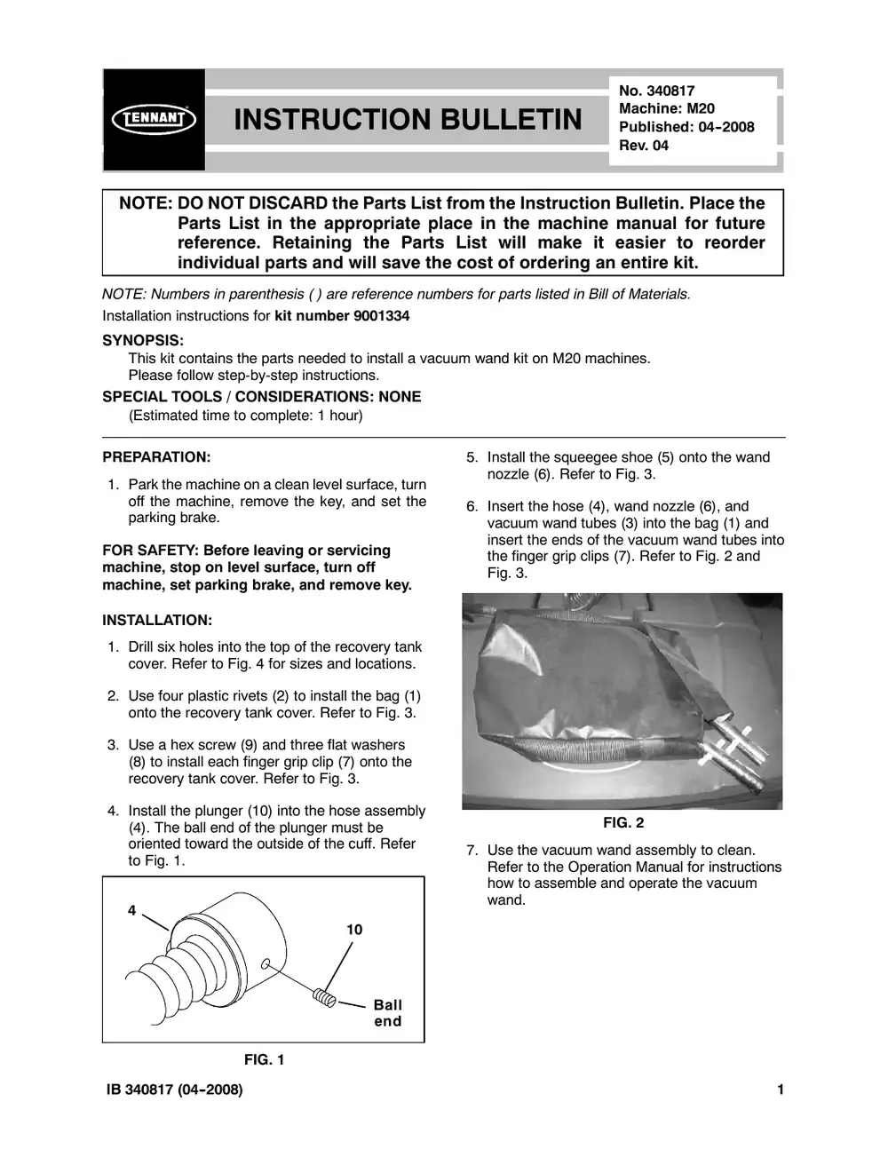
Tennant M20 instruction bulletin 340817, page 1 of 3
Page 1 of 3 SES ref PF-DERJ-HL6Q‌‌​⁠‍‍‌​‌​‍‌⁠‌⁠​⁠‌‌⁠‌‌‍‌‍⁠‍‍​​​‌​‍‌​‌‍⁠‌⁠⁠‌⁠‌​‍⁠⁠‍‍‌​‍​​‌​​⁠
Text of this page
INSTRUCTION B NOTE: DO NOT DISCARD the Parts List Parts List in the appropriate pla reference. Retaining the Parts individual parts and will save the NOTE: Numbers in parenthesis ( ) are reference num Installation instructions for kit number TN4019673 SYNOPSIS: This kit contains the parts needed to install a vacu Please follow step-by-step instructions. SPECIAL TOOLS / CONSIDERATIONS: NONE (Estimated time to complete: 1 hour) PREPARATION: 1. Park the machine on a clean level surface, turn off the machine, remove the key, and set the parking brake. FOR SAFETY: Before leaving or servicing machine, stop on level surface, turn off machine, set parking brake, and remove key. INSTALLATION: 1. Drill six holes into the top of the recovery tank cover. Refer to Fig. 4 for sizes and locations. 2. Use four plastic rivets (2) to install the bag (1) onto the recovery tank cover. Refer to Fig. 3. 3. Use a hex screw (9) and three flat washers (8) to install each finger grip clip (7) onto the recovery tank cover. Refer to Fig. 3. 4. Install the plunger (10) into the hose assembly (4). The ball end of the plunger must be oriented toward the outside of the cuff. Refer to Fig. 1. 4 10 Ball end FIG. 1 IB 340817 (04--2008) No. 340817 Machine: M20 BULLETIN Published: 04--2008 Rev. 04 from the Instruction Bulletin. Place the ace in the machine manual for future s List will make it easier to reorder e cost of ordering an entire kit. mbers for parts listed in Bill of Materials. uum wand kit on M20 machines. 5. Install the squeegee shoe (5) onto the wand nozzle (6). Refer to Fig. 3. 6. Insert the hose (4), wand nozzle (6), and vacuum wand tubes (3) into the bag (1) and insert the ends of the vacuum wand tubes into the finger grip clips (7). Refer to Fig. 2 and Fig. 3. FIG. 2 7. Use the vacuum wand assembly to clean. Refer to the Operation Manual for instructions how to assemble and operate the vacuum wand. 1
Tennant M20 instruction bulletin 340817, page 2 of 3
Page 2 of 3
Text of this page
5 6 10 3 4 1 9 2 7 8 FIG. 3 2 IB 340817 (04--2008)
Tennant M20 instruction bulletin 340817, page 3 of 3
Page 3 of 3
Text of this page
FIG. 4 Bill of Materials for Wand Kit, Vacuum, CI [M20]--TN4019673 Tennant Ref. Part No. Description Qty. o TN4019673 Wand Kit, Vacuum, CI [M20] 1 Y 1 TN4017746 Bag, Power 1 Y 2 TN4016302 Rivet, Plstc, .250 X 0.898 4 Y 3 TN4017057 Tube, Wand, Vacuum, Metal [1pick=1box] 1 Y 4 TN4018319 Hose Assy, W/2cuff, 1.5d 84l [Vacwand] 1 Y 5 TN4017055 Shoe, Plstc, Sqge, 14.0 1 Y 6 TN4017060 Nozzle, Wand, Plstc, 14.0lg 1 Y 7 TN4017922 Clip, Grip, Finger, 1.00--1.88d White,Vyl 2 Y 8 TN4042242 Washer, Flat, #06 6 Y 9 TN4029085 Screw, Hex, M5 X 0.8 X 16, Fmg 2 Y 10 TN4018360 Plunger 1 TENNANT COMPANY P. O. Box 1452 Minneapolis, MN 55440-1452 IB 340817 (04--2008) 3

Panel Kit, Instmt, Repair [M20]

Tennant instruction bulletin 340807 rev. 02Published 02-2007Kit 9002434

What it’s for: Replace the control panel assembly on M20 machines.

  • Machines: M20
  • M20: all
  • Power: gasoline, LPG and diesel
  • Applies to: detergent

Time: 1 hour · Special tools: NONE

Safety warnings (from the bulletin, word for word)

  • FOR SAFETY: Before leaving or servicing machine, stop on level surface, set parking brake, turn off machine, and remove key.
  • WARNING: Always disconnect battery cables from machine before working on electrical components.

Parts

Parts for Tennant instruction bulletin 340807
ItemPart numberQtyDescriptionPrice
TN9002434Old # 90024341Panel Kit, Instmt, Repair [M20]KitCall for availability 800-440-6723
1TN1018410Old # 10184101Circuitboard Assy [M20/T20]Call for availability 800-440-6723
2TN1018410Old # 10184104Nut, Hex, Lock, M4 X 0.70, NL, SSCall for availability 800-440-6723
3TN4031353Old # 10293624Washer, Shld, Nyl [8--32]$0.15/EA

Bulletin PDF: Sign in to view or downloadSign in to download

Installation instructions (3 pages)
Tennant M20 instruction bulletin 340807, page 1 of 3
Page 1 of 3 SES ref PF-5MTQ-LEPZ‌‌​⁠‍‍‌​‌​‍‌⁠‌⁠​⁠‌‌⁠‌‍‍​⁠⁠‍⁠​​​‌​‍‌​‌⁠​‍⁠⁠​​​‍​⁠‌⁠‌​‍‌​⁠‌​‍​
Text of this page
INSTRUCTION NOTE: DO NOT DISCARD the Parts List Parts List in the appropriate pla reference. Retaining the Parts individual parts and will save the NOTE: Numbers in parenthesis ( ) are reference num Installation instructions for kit number TN9002434 SYNOPSIS: This kit contains the parts needed to replace the c Please follow step-by-step instructions. SPECIAL TOOLS / CONSIDERATIONS: NONE (Estimated time to complete: 1 hour) NOTE: Record hours from the hour meter before rem new control panel (1) is set to zero hours. Tennant Se Administrative Associate (NOT Warranty). NOTE: If custom settings are used (ask operator/cust board from the machine. Machine defaults back to fac pressure, solution delivery, and detergent delivery set custom settings are used. Consult the Tennant Techn read, and reset custom settings. PREPARATION: 1. Park machine on a clean level surface, turn off machine, remove key, and set parking brake. FOR SAFETY: Before leaving or servicing machine, stop on level surface, set parking brake, turn off machine, and remove key. 2. First disconnect the negative terminal and then the positive terminal from the battery. Remove the battery from the machine. WARNING: Always disconnect battery cables from machine before working on electrical components. 3. Disconnect the two main wire harness connectors from the circuit board. 4. Remove the two hex nuts holding the battery flap and retaining bar to the back of the dash panel. Set the battery flap and retaining bar aside. Mounting hardware has changed, discard existing hex nuts. Refer to Fig. 2. IB 340807 (02--2007) No. 340807 Machine: M20 N BULLETIN Published: 02--2007 Rev. 02 from the Instruction Bulletin. Place the ace in the machine manual for future s List will make it easier to reorder e cost of ordering an entire kit. mbers for parts listed in Bill of Materials. control panel assembly on M20 machines. moving the old control panel from the machine. The ervice Representatives please call Business tomer), record settings before removing the control ctory settings after circuit board is replaced. Down ttings must be changed back to custom settings if nical Support Group for instructions how to access, 5. Remove the two hex nuts holding the bottom of the control panel to the back of the dash panel. Mounting hardware has changed, discard existing hex nuts. Refer to Fig. 2. 6. Remove the control panel from the dash panel. Send the control panel back to Tennant Warranty Department. Refer to Fig. 2. INSTALLATION: 1. Use four hex nuts (2) and four nylon bushings (3) to install the new control panel (1), battery cover, and retaining bar onto the dash panel. Refer to Fig. 2. NOTE: The nylon bushings (3) must be installed as shown in Fig. 2 to prevent static electricity from damaging the control panel (1). 2. Reconnect the main wire harness to the control panel (1). 3. Set the battery into the battery compartment. Reconnect the positive terminal first and then the negative terminal. 1
Tennant M20 instruction bulletin 340807, page 2 of 3
Page 2 of 3
Text of this page
NOTE: Refer to Steps 4 through 6 to reconfigure the control panel (1) so it matches the machine. 4. To enter configuration mode: Simultaneously press and hold the 4/5 button (A) and Side Brush button (B) and turn the ignition switch to the on position (without starting machine). Refer to Fig. 1. D 0/1 C 2/3 A B 4/5 6/7 8/9 FIG. 1 Control Panel Labe 1 3 2 Battery F FIG 2 5. To select configuration: Use the 2/3 button (C) to scroll to the proper mode (ES, FaST, or No ES, No FaST option from the menu) and use the 0/1 (D) button to select the applicable mode. Refer to Fig. 1. 6. If machine is equipped with the Side Brush Sweep Only option reenter the configuration mode and select Side Brush Sweep Only from the configuration menu. Refer to Fig. 1. NOTE: If custom settings are used (ask operator/customer), record settings before removing the control board from the machine. Machine defaults back to factory settings after circuit board is replaced. Down pressure, solutiondelivery,anddetergent deliverysettings must be changed back to custom settings if custom settings are used. Consult the Tennant Technical Support Group for instructions how to read and reset custom settings. 7. Start and test the machine. Verify the machine operates properly. el Nylon bushings (3) must be installed as shown Dash Panel 3 Retaining Bar 2 Flap G. 2 IB 340807 (02--2007)
Tennant M20 instruction bulletin 340807, page 3 of 3
Page 3 of 3
Text of this page
Bill of Materials for Panel Kit, Instmt, Repair [M20]--TN9002434 Tennant Ref. Part No. Description Qty. o TN9002434 ) Panel Kit, Instmt, Repair [M20] 1 Y 1 TN1018410 Circuitboard Assy [M20/T20] 1 Y 2 TN1018410 Nut, Hex, Lock, M4 X 0.70, NL, SS 4 Y 3 TN4031353 Washer, Shld, Nyl [8--32] 4 TENNANT COMPANY P. O. Box 1452 Minneapolis, MN 55440-1452 IB 340807 (02--2007) 3

Light Kit, Revl, CI [M20 & T20]

Tennant instruction bulletin 340816 rev. 01Published 03-2007Kit 9001331

What it’s for: Install a revolving light kit on M20/T20 machines.

  • Machines: M20, T20
  • M20: all
  • Power: gasoline, LPG and diesel
  • Applies to: lights

Time: 1 hour · Special tools: NONE

Safety warnings (from the bulletin, word for word)

  • FOR SAFETY: Before leaving or servicing machine, stop on level surface, set parking brake, turn off machine, and remove key.
  • WARNING: Always disconnect battery cables from machine before working on electrical components.

Parts

Parts for Tennant instruction bulletin 340816
ItemPart numberQtyDescriptionPrice
TN4019671Old # 90013311Light Kit, Revl, CI [M20 & T20]Kit$767.90/EA
2TN4035367Old # 241962Screw, Pan, M5 X 0.8 X 20, SS$3.20/EA
3TN4042244Old # 190662Washer, Flat, #10$2.50/EA
4TN4041991Old # 097392Nut, Hex, Lock, M5 X 0.8, NL, SS$3.30/EA
5TN4035919Old # 10194451Bracket, Sppt, Revl Light$55.20/EA
6TN4041992Old # 097404Screw, Hex, M8 X 1.25 X 20, SS$3.30/EA
7TN4035242Old # 10172184Washer, Flat, 0.32B 1.00D .12, SS$3.40/EA
8TN4036226Old # 10199711Harness, Warning / Backup [M20 & T20]$27.50/EA
9TN4013452Old # 462362Clamp, Cable, Stl, 0.25D X 0.56W, 1Hole$3.60/EA

Bulletin PDF: Sign in to view or downloadSign in to download

Installation instructions (4 pages)
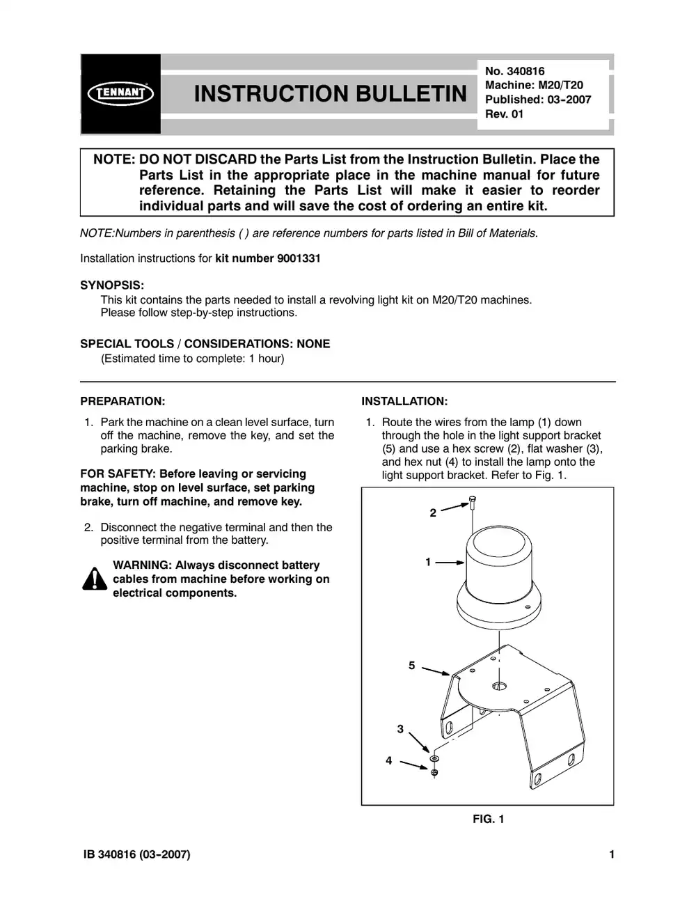
Tennant M20 instruction bulletin 340816, page 1 of 4
Page 1 of 4 SES ref PF-UHNF-UVDF‌‌​⁠‍‍‌​‌​‍‌⁠‌⁠​⁠‌‌⁠‌‍‍‌​‍⁠​​​​‌​‍‌​⁠‍⁠​‍‌‌‌‌​‌​‍⁠⁠‍​​​‌​‌‌​
Text of this page
INSTRUCTION NOTE: DO NOT DISCARD the Parts List Parts List in the appropriate pla reference. Retaining the Parts individual parts and will save the NOTE:Numbers in parenthesis ( ) are reference numb Installation instructions for kit number TN4019671 SYNOPSIS: This kit contains the parts needed to install a revo Please follow step-by-step instructions. SPECIAL TOOLS / CONSIDERATIONS: NONE (Estimated time to complete: 1 hour) PREPARATION: 1. Park the machine on a clean level surface, turn off the machine, remove the key, and set the parking brake. FOR SAFETY: Before leaving or servicing machine, stop on level surface, set parking brake, turn off machine, and remove key. 2. Disconnect the negative terminal and then the positive terminal from the battery. WARNING: Always disconnect battery cables from machine before working on electrical components. IB 340816 (03--2007) No. 340816 Machine: M20/T20 N BULLETIN Published: 03--2007 Rev. 01 from the Instruction Bulletin. Place the ace in the machine manual for future s List will make it easier to reorder e cost of ordering an entire kit. bers for parts listed in Bill of Materials. olving light kit on M20/T20 machines. INSTALLATION: 1. Route the wires from the lamp (1) down through the hole in the light support bracket (5) and use a hex screw (2), flat washer (3), and hex nut (4) to install the lamp onto the light support bracket. Refer to Fig. 1. 2 1 5 3 4 FIG. 1 1
Tennant M20 instruction bulletin 340816, page 2 of 4
Page 2 of 4
Text of this page
2. Route the wires from the lamp (1) through one cable clamp (9) and use a hex screw (2), two flat washers (3), and hex screw (4) to install the cable clamp underneath the lamp support bracket (5) and completely secure the lamp to the light support bracket. Refer to Fig. 2. 2 1 3 5 3 9 4 FIG. 2 3. Open the recovery tank cover and pull the main wire harness backup alarm and revolving light connector from between the recovery and solution tank. Connect the warning/backup harness (8) to the main wire harness. Refer to Fig. 3 or Fig. 4, and Fig. 9. FIG. 3 -- M20 Harness Location FIG. 4 -- T20 Harness Location 2 4. Route the warning/backup harness (8) through the notch in the solution tank and install a cable clamp (9) onto the warning/ backup harness. Refer to Fig. 6. 5. Use three hex screws (6) and three flat washers (7) to install the light support bracket (5) onto the solution tank. Refer to Fig. 5. 5 7 6 FIG. 5 6. Use a hex screw (6) and flat washer (7) to install the cable clamp (9) on the warning/ backup harness (8) onto light support bracket (5) and solution tank. Refer to Fig. 6. 5 Cable routing 6 7 9 FIG. 6 IB 340816 (03--2007)
Tennant M20 instruction bulletin 340816, page 3 of 4
Page 3 of 4
Text of this page
7. Connect the warning/backup harness (8) to the light (1). Refer to Fig. 8 and Fig. 9. 8. Neatly bundle the remaining length of the warning/backup harness (8) and use a cable tie or electrical tape to hold the bundled wire together. Refer to Fig. 7. FIG. 7 2 3 4 6 7 9 FIG IB 340816 (03--2007) 9. Slide the main wire harness backup alarm and revolving light connector and attached connector from the warning/backup harness (8) back down between the recovery and solution tank and close the recovery tank cover. Refer to Fig. 3 or Fig. 4. 10. Reconnect the positive terminal and then the negative terminal to the battery. 11. Start the machine and test the light. 1 5 3 9 3 4 8 Connect to main wire harness G. 8 3
Tennant M20 instruction bulletin 340816, page 4 of 4
Page 4 of 4
Text of this page
FIG. 9 Bill of Materials for Light Kit, Revl, CI [M20 & T20]--TN4019671 Tennant Ref. Part No. Description Qty. o TN4019671 ) Light Kit, Revl, Ci [M20 & T20] 1 Yo 1 1017250 Lamp, Strobe, Amb [12--48 VDC] 1 YY 9000879 Lens, Lamp, Amb, Strobe/Flasher 1 YY 9000846 Lamp, Bulb, Lamp, Strobe 1 YY 55272 Terminal, Bullet, Mal, .157D, 12Ga 2 Y 2 TN4035367 ) Screw, Pan, M5 X 0.8 X 20, SS 2 Y 3 TN4042244 Washer, Flat, #10 2 Y 4 TN4041991 Nut, Hex, Lock, M5 X 0.8, NL, SS 2 Y 5 TN4035919 Bracket, Sppt, Revl Light 1 Y 6 TN4041992 Screw, Hex, M8 X 1.25 X 20, SS 4 Y 7 TN4035242 ) Washer, Flat, 0.32B 1.00D .12, SS 4 Y 8 TN4036226 Harness, Warning / Backup [M20 & T20] 1 Y 9 TN4013452 Clamp, Cable, Stl, 0.25D X 0.56W, 1Hole 2 TENNANT COMPANY P. O. Box 1452 Minneapolis, MN 55440-1452 4 IB 340816 (03--2007)

Guard Kit, Sqge, CI [M20]

Tennant instruction bulletin 340818 rev. 01Published 04-2012Kit 9001338

What it’s for: Install a rear squeegee protector on M20 machines.

  • Machines: M20
  • M20: all
  • Power: gasoline, LPG and diesel

Time: 3/4 hour · Special tools: NONE

Safety warnings (from the bulletin, word for word)

  • FOR SAFETY: Before leaving or servicing machine, stop on level surface, set parking brake, turn off machine, and remove key.

Parts

Parts for Tennant instruction bulletin 340818
ItemPart numberQtyDescriptionPrice
TN4019675Old # 90013381Guard Kit, Sqge, CI [M20]Kit$687.93/EA
1TN4030640Old # 10275602Bracket Wldt, Guard, Sqge$92.00/EA
2TN4019759Old # 392844Screw, Hex, M10 X 1.5 X 35, 8.8$4.00/EA
3TN4034138Old # 3249210Washer, Flat, 0.38, Std$2.50/EA
4TN4033860Old # 10249772Bumper, Ure, 1.50D 1.25L$35.00/EA
5TN4039391Old # 211962Screw, Hex, .38--16 X 0.88, G5$2.50/EA
6TN4038473Old # 10561951Guard Wldt, Pntd, [M20 / T20]Call for availability 800-440-6723
7TN4041290Old # 069652Screw, Hex, M10 X 1.5 X 80, 8.8$6.80/EA
8TN4016826Old # 414302Nut, Hex, Lock, M10 X 1.5, NL$4.00/EA
9TN4031918Old # 3693591Pin, Hitch, .375D X 3.12L, PL$7.50/EA
10TN4029376Old # 577021Cable, Glv, .06D 012.0L .26Eye/.26Eye$9.50/EA
11TN4029085Old # 558451Screw, Hex, M5 X 0.8 X 16, Fmg$4.00/EA
12TN4042888Old # 016831Washer, Flat, #10, SS$2.60/EA
13TN4042522Old # 10454442Guard Wldt, Sqge$171.70/EA
14TN4019761Old # 392854Screw, Hex, M10 X 1.5 X 40, 8.8$3.20/EA
15TN4194632Old # 10295432Plate, MtgCall for availability 800-440-6723
16TN4016797Old # 411874Washer, Flat, Belleville, .38$4.10/EA

Bulletin PDF: Sign in to view or downloadSign in to download

Installation instructions (4 pages)
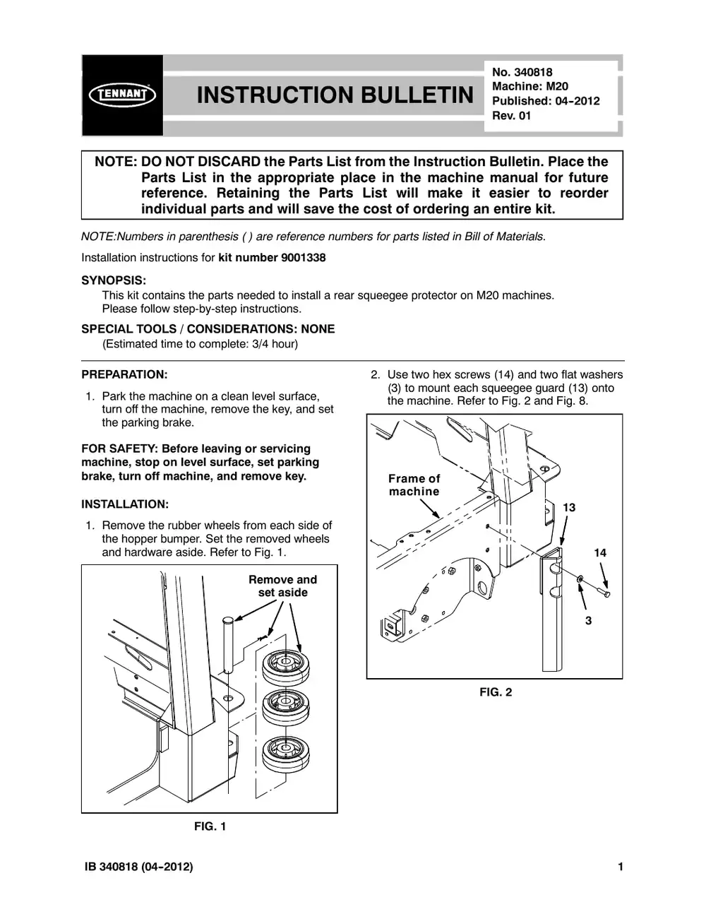
Tennant M20 instruction bulletin 340818, page 1 of 4
Page 1 of 4 SES ref PF-BCQC-5CMK‌‌​⁠‍‍‌​‌​‍‌⁠‌⁠​⁠‌‌⁠‌​‌​​‍‍⁠​​​‌​‍‌​‍‍​‍‌‌​‌⁠‌​‍‌​⁠‍‍‌⁠​‍‍‌‍
Text of this page
INSTRUCTION NOTE: DO NOT DISCARD the Parts List Parts List in the appropriate pla reference. Retaining the Parts individual parts and will save the NOTE:Numbers in parenthesis ( ) are reference numb Installation instructions for kit number TN4019675 SYNOPSIS: This kit contains the parts needed to install a rear Please follow step-by-step instructions. SPECIAL TOOLS / CONSIDERATIONS: NONE (Estimated time to complete: 3/4 hour) PREPARATION: 1. Park the machine on a clean level surface, turn off the machine, remove the key, and set the parking brake. FOR SAFETY: Before leaving or servicing machine, stop on level surface, set parking brake, turn off machine, and remove key. INSTALLATION: 1. Remove the rubber wheels from each side of the hopper bumper. Set the removed wheels and hardware aside. Refer to Fig. 1. Remove and set aside FIG. 1 IB 340818 (04--2012) No. 340818 Machine: M20 N BULLETIN Published: 04--2012 Rev. 01 from the Instruction Bulletin. Place the ace in the machine manual for future s List will make it easier to reorder e cost of ordering an entire kit. bers for parts listed in Bill of Materials. r squeegee protector on M20 machines. 2. Use two hex screws (14) and two flat washers (3) to mount each squeegee guard (13) onto the machine. Refer to Fig. 2 and Fig. 8. Frame of machine 13 14 3 FIG. 2 1
Tennant M20 instruction bulletin 340818, page 2 of 4
Page 2 of 4
Text of this page
3. Use a hex screw (5) and a flat washer (3) to install a bumper (4) onto each squeegee guard bracket (1). Refer to Fig. 3 and Fig. 8. 4 1 3 5 FIG. 3 4. Slide the mounting plate (15) into the hole in the hopper bumper where the rubber wheels were located, align the mounting plate with the mounting holes in the hopper bumper, and use two hex screws (2), two flat washers (3), and a mounting plate to install squeegee guard bracket (1) to the frame of the machine. Repeat this step to install the other squeegee guard bracket onto the machine. Refer to Fig. 4 and Fig. 8. 1 2 3 15 FIG. 4 5. Reinstall all parts removed from the hopper bumper at the beginning of the procedure. Refer to Fig. 1. 2 6. Use two hex screws (7), four flat washers (3), and two hex nuts (8) to install the rear squeegee guard (6) onto the squeegee guard brackets (1). Refer to Fig. 5 and Fig. 8. 3 6 8 3 7 3 8 1 FIG. 5 7. Install the hitch pin (9) ring onto the 12” cable (10). 8. Use a forming hex screw (11) and a flat washer (12) to install the 12” cable (10) onto the hopper. Refer to Fig. 6, Fig. 7, and Fig. 8. 12 11 10 FIG. 6 IB 340818 (04--2012)
Tennant M20 instruction bulletin 340818, page 3 of 4
Page 3 of 4
Text of this page
9. Engage the rear squeegee protector: Pull the pin (9) from the squeegee guard bracket (1) and rear squeegee guard (6), lower the rear squeegee guard, and reinsert the pin into the squeegee guard bracket. Refer to Fig. 7. FIG. 7 15 14 3 8 1 13 FIG IB 340818 (04--2012) 10. Disengage the rear squeegee protector: Pull the pin from the squeegee guard bracket (1), lift the rear squeegee guard (6), and reinsert the pin into the squeegee guard bracket and the rear squeegee guard. Refer to Fig. 7. 3 3 6 3 2 3 1 2 9 10 7 11 3 12 7 4 3 5 3 1 8 5 4 3 15 3 13 14 G. 8 3
Tennant M20 instruction bulletin 340818, page 4 of 4
Page 4 of 4
Text of this page
Bill of Materials for Guard Kit, Sqge, CI [M20]--TN4019675 Tennant Ref. Part No. Description Qty. o TN4019675 ) Guard Kit, Sqge, CI [M20] 1 Y 1 TN4030640 Bracket Wldt, Guard, Sqge 2 Y 2 TN4019759 Screw, Hex, M10 X 1.5 X 35, 8.8 4 Y 3 TN4034138 Washer, Flat, 0.38, Std 10 Y 4 TN4033860 ) Bumper, Ure, 1.50D 1.25L 2 Y 5 TN4039391 Screw, Hex, .38--16 X 0.88, G5 2 Y 6 TN4038473 Guard Wldt, Pntd, [M20 / T20] 1 Y 7 TN4041290 Screw, Hex, M10 X 1.5 X 80, 8.8 2 Y 8 TN4016826 Nut, Hex, Lock, M10 X 1.5, NL 2 Y 9 TN4031918 ) Pin, Hitch, .375D X 3.12L, PL 1 Y 10 TN4029376 Cable, Glv, .06D 012.0L .26Eye/.26Eye 1 Y 11 TN4029085 Screw, Hex, M5 X 0.8 X 16, Fmg 1 Y 12 TN4042888 Washer, Flat, #10, SS 1 Y 13 TN4042522 Guard Wldt, Sqge 2 Y 14 TN4019761 ) Screw, Hex, M10 X 1.5 X 40, 8.8 4 Y 15 TN4194632 Plate, Mtg 2 Y 16 TN4016797 Washer, Flat, Belleville, .38 4 TENNANT COMPANY P. O. Box 1452 Minneapolis, MN 55440-1452 4 IB 340818 (04--2012)

OHG Harness (5) FIG. 11 Bill of Materials for Light Kit, Revl, W/OHG, CI [M20 and T20]

Tennant instruction bulletin 340819 rev. 02Published 03-2007Kit 9001717

What it’s for: Install an OHG revolving light kit on M20/T20 machines.

  • Machines: M20, T20
  • M20: all
  • Power: gasoline, LPG and diesel
  • Applies to: overhead guard, lights

Time: 1 hour · Special tools: NONE

Safety warnings (from the bulletin, word for word)

  • FOR SAFETY: Before leaving or servicing machine, stop on level surface, set parking brake, turn off machine, and remove key.
  • WARNING: Always disconnect battery cables from machine before working on electrical components.

Parts

Parts for Tennant instruction bulletin 340819
ItemPart numberQtyDescriptionPrice
TN4019723Old # 90017171OHG Harness (5) FIG. 11 Bill of Materials for Light Kit, Revl, W/OHG, CI [M20 and T20]Kit$164.46/EA
1TN4035245Old # 10172501Light, Strobe, Amb, 12--48VDCCall for availability 800-440-6723
2TN4035367Old # 241962Screw, Pan, M5 X 0.8 X 20, SS$3.20/EA
3TN4042244Old # 190662Washer, Flat, #10$2.50/EA
4TN4041991Old # 097392Nut, Hex, Lock, M5 X 0.80, NL, SS$3.30/EA
5TN4036203Old # 10196471Harness, Warning / OHG [M20]$23.56/EA
7TN4011909Old # 7631154Tie, Cable, 6.0L, 1.25D Max$2.30/EA
8TN4014138Old # 492662Tie, Cable, Nyl, 07.3L .19W 1.8 Max D$2.50/EA

Bulletin PDF: Sign in to view or downloadSign in to download

Installation instructions (5 pages)
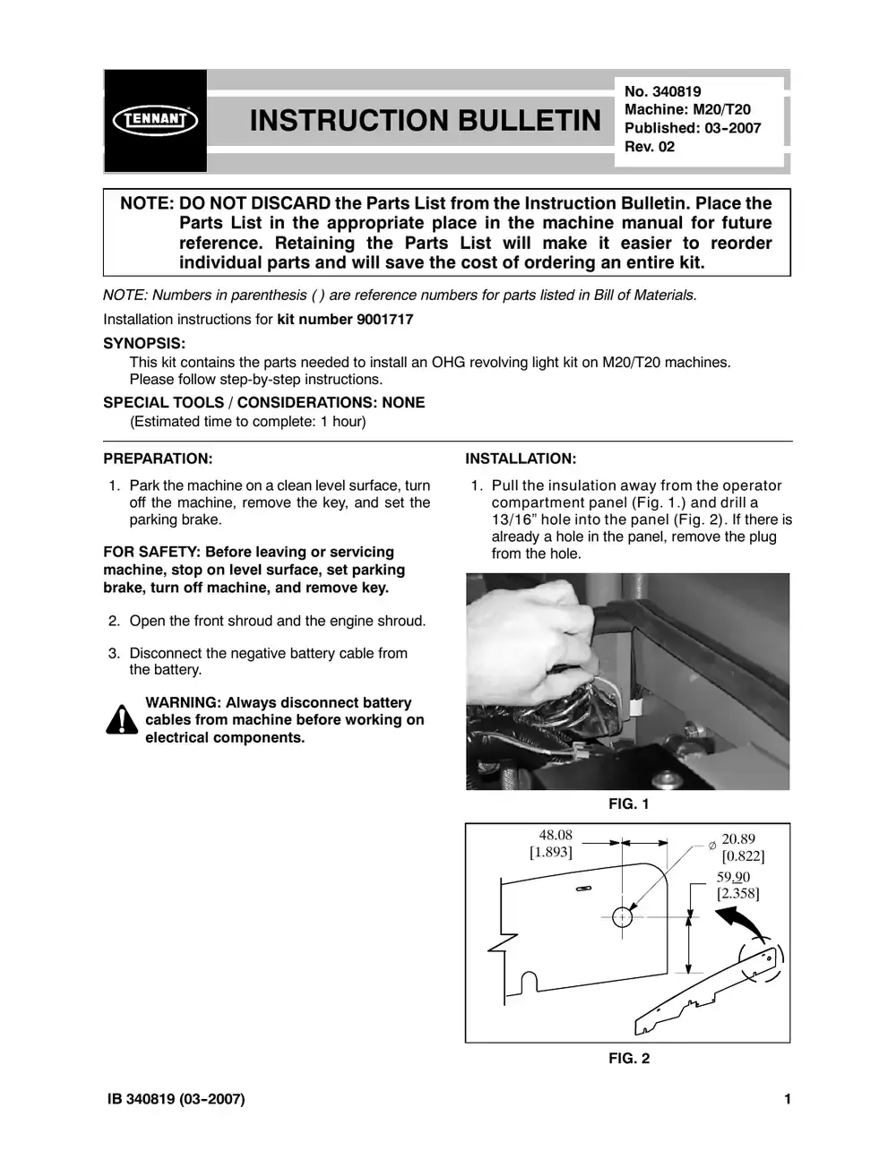
Tennant M20 instruction bulletin 340819, page 1 of 5
Page 1 of 5 SES ref PF-DZNT-C4UZ‌‌​⁠‍‍‌​‌​‍‌⁠‌⁠​⁠‌‌⁠‌⁠‌​‍⁠⁠‌​​​‌​‍‌​‌⁠​‍​​‌‌‌⁠​​‍⁠‍⁠​‌‍‍​⁠‌‌
Text of this page
INSTRUCTION NOTE: DO NOT DISCARD the Parts List Parts List in the appropriate pla reference. Retaining the Parts individual parts and will save the NOTE: Numbers in parenthesis ( ) are reference num Installation instructions for kit number TN4019723 SYNOPSIS: This kit contains the parts needed to install an OH Please follow step-by-step instructions. SPECIAL TOOLS / CONSIDERATIONS: NONE (Estimated time to complete: 1 hour) PREPARATION: 1. Park the machine on a clean level surface, turn off the machine, remove the key, and set the parking brake. FOR SAFETY: Before leaving or servicing machine, stop on level surface, set parking brake, turn off machine, and remove key. 2. Open the front shroud and the engine shroud. 3. Disconnect the negative battery cable from the battery. WARNING: Always disconnect battery cables from machine before working on electrical components. IB 340819 (03--2007) No. 340819 Machine: M20/T20 N BULLETIN Published: 03--2007 Rev. 02 from the Instruction Bulletin. Place the ace in the machine manual for future s List will make it easier to reorder e cost of ordering an entire kit. mbers for parts listed in Bill of Materials. HG revolving light kit on M20/T20 machines. INSTALLATION: 1. Pull the insulation away from the operator compartment panel (Fig. 1.) and drill a 13/16” hole into the panel (Fig. 2). If there is already a hole in the panel, remove the plug from the hole. FIG. 1 48.08 20.89 [1.893] [0.822] 59.90 [2.358] FIG. 2 1
Tennant M20 instruction bulletin 340819, page 2 of 5
Page 2 of 5
Text of this page
2. Insert a grommet (6) into the hole in the operator compartment panel (Fig. 3) and the hole on top the overhead guard (Fig. 4). FIG. 3 6 FIG. 4 2 3. Route the wires from the light (1) down through the grommet (6) installed in the overhead guard and use two hex screws (2), flat washers (3), and hex nuts (4) to install the light onto the overhead guard. (Fig. 5) 4 3 1 6 2 FIG. 5 4. Connect the warning/overhead harness (5) to the main wire harness, route the warning/ overhead harness through the grommet installed in the operator compartment panel, up along leg of the overhead guard, and to the rear cross member of the overhead guard. (Fig. 10 and Fig. 11) IB 340819 (03--2007)
Tennant M20 instruction bulletin 340819, page 3 of 5
Page 3 of 5
Text of this page
5. Insert a grommet (6) into the rear hole in the rear cross member of the overhead guard and route the warning/overhead harness (5) through the grommet and the front hole in the rear cross member. (Fig. 6) Install first before routing warning/ overheadharness (5) through cross member 6 Install after routing warning/overhead harness (5) through cross member FIG. 6 6. Slide the remaining grommet (6) onto the warning/overhead harness (5) and insert the grommet into the front hole in the rear cross member of the overhead guard. (Fig. 6) 7. Route the warning/OHG harness (5) through the notch in the overhead guard insulation and connect the warning/OHG harness to the light (1). (Fig. 7 and Fig. 11) FIG. 7 IB 340819 (03--2007) 8. Use four cable ties (7) to secure the warning/ overhead harness (5) to the leg of the overhead guard. (Fig. 8 and Fig. 9) FIG. 8 FIG. 9 9. Use two cable ties (8) to secure the warning/ overhead harness (5) to the top of the overhead guard. (Fig. 10) 10. Reconnect the negative battery cable to the battery. 11. Start and test the machine to ensure the overhead guard light operates. 3
Tennant M20 instruction bulletin 340819, page 4 of 5
Page 4 of 5
Text of this page
1 6 2 Connect to wires from revolving light (1) FRONT Locations for cable ties (8) securing warning/overhead harness (5) to top of overhead guard REAR FIG 4 4 3 REAR 7 Refer to Fig. 8 and Fig. 9 for locations of wire ties (7) on overhead guard 5 6 Connect to main wire harness G. 10 IB 340819 (03--2007)
Tennant M20 instruction bulletin 340819, page 5 of 5
Page 5 of 5
Text of this page
Main Wire Harness Warning/OHG Harness (5) FIG. 11 Bill of Materials for Light Kit, Revl, W/OHG, CI [M20 and T20]--TN4019723 Tennant Ref. Part No. Description Qty. o TN4019723 ) Light Kit, Revl, W/OHG, CI [M20 and T20] 1 Y 1 TN4035245 Light, Strobe, Amb, 12--48VDC 1 Y 2 TN4035367 Screw, Pan, M5 X 0.8 X 20, SS 2 Y 3 TN4042244 Washer, Flat, #10 2 Y 4 TN4041991 Nut, Hex, Lock, M5 X 0.80, NL, SS 2 Y 5 TN4036203 ) Harness, Warning / OHG [M20] 1 Y 6 10632--17 Grommet, Rbr, 0.50ID, F/0.8H, .12 Matl 4 Y 7 TN4011909 Tie, Cable, 6.0L, 1.25D Max 4 Y 8 TN4014138 Tie, Cable, Nyl, 07.3L .19W 1.8 Max D 2 TENNANT COMPANY P. O. Box 1452 Minneapolis, MN 55440-1452 IB 340819 (03--2007) 5

Rad W/Screen Kit, Replmt [M20/T20 G/LP]

Tennant instruction bulletin 9012828 rev. 00Published 10-2014Kit 9012811

What it’s for: Install a radiator screen kit on M20 / T20 machines. (Gas / LPG machines only). Tennant NA: M20 (Serial Numbers 000000- 003038), T20 (Serial Numbers 000000- 002092) Tennant CE: M20 (Serial Numbers 0000- 0195), T20 (Serial Numbers 0000- 0188)

  • Machines: M20, T20
  • M20 SN 000000–003038
  • Power: Gasoline, LPG

Time: 8 hours · Special tools: NONE

Safety warnings (from the bulletin, word for word)

  • FOR SAFETY: Before leaving or servicing machine, stop on level surface, turn off machine, set parking brake, and remove key.
  • FOR SAFETY: When servicing machine, avoid contact with hot engine coolant, do not remove cap from radiator when engine is hot, and allow engine to cool.

Parts

Parts for Tennant instruction bulletin 9012828
ItemPart numberQtyDescriptionPrice
TN9012811Old # 90128111Rad W/Screen Kit, Replmt [M20/T20 G/LP]KitCall for availability 800-440-6723
1TN4042691Old # 10459401Radiator, W/ Hyd Cooler [Side X Side]Call for availability 800-440-6723
2TN4042665Old # 10457641Cap, Radiator, 14PSI [Stant]$10.90/EACall for availability
3TN4190181Old # 10469621Bracket, Mtg, Radiator$26.70/EA
4TN4041287Old # 069622Screw, Hex, M10 X 1.50 X 45, 8.8$4.00/EA
5TN4015364Old # 542744Isolator, Vib, Bshg, 1.1d 0.6l .4b 0.78h$14.70/EA
6TN4037922Old # 101456316Washer, Flat, 0.40b 1.12d .12, SS$5.80/EA
7TN4016826Old # 414304Nut, Hex, Lock, M10 X 1.5, Nl$4.00/EA
8TN4156940Old # 392772Screw, Hex, M8 X 1.25 X 25, 8.8$3.20/EA
9TN4034137Old # 324912Washer, Flat, 0.31, Std$2.50/EA
10TN4189416Old # 10438971Bracket, Skirt, Rbr$30.10/EA
11TN4188116Old # 10521701Skirt, Eng Fan, Gas / Lp$83.33/EA
12TN4029864Old # 3613392Screw, Hex, M6 X 1.00 X 16, Fmg$4.00/EA
13TN4045641Old # 10373552Screw, Hex, M8 X 1.25 X , 9.8, SEMS$2.50/EA
14TN4016794Old # 411783Washer, Flat, 0.25, Fendr$2.50/EA
15TN4045568Old # 10368923Screw, Hex, M6 X 1.00 X 25, 9.8 SEMS$2.50/EA
16TN4014138Old # 492661Tie, Cable, Nyl, 07.3l .19w 1.8 Max D$2.50/EA
17TN4044400Old # 10404672Screw, Hex, M6 X 1.00 X 20, 9.8, SEMS$3.30/EA
18TN1071041Old # 10710411Bracket Wldt, Radiator, Fan, Gas/LPGCall for availability 800-440-6723
19TN1071033Old # 10710331Frame Wldt, Screen, RadCall for availability 800-440-6723
20TN1071047Old # 10710471Plate, Cover, ScreenCall for availability 800-440-6723
21TN4038497Old # 10544281Shroud, Fan$126.20/EA
22TN4032038Old # 10315661Fan, Cooling, 14.1d, 6 Blade, 0.5b Taper$174.80/EA
23TN4180322Old # 10725051Sheave, Mach [Gm1.6l 2615rpm Fan]Call for availability 800-440-6723
24TN1051534Old # 10515341Concept, LatchCall for availability 800-440-6723
25TN4186796Old # 10587771Bracket, Shrd, Fan, Upper, Sppt, Gas/Lpg$36.56/EA
26TN4036767Old # 10587531Bracket, Shrd, Fan, Lower, Gas/Lpg$10.20/EA
27TN4185825Old # 10644431Bracket, Shrd, Radiator, Gas/Lpg, CE$29.80/EA
28TN4036249Old # 10202342Screw, Hex, M4 X 0.70 X 10, SS$3.30/EA
29TN4043235Old # 028502Nut, Hex, Lock, M4 X 0.70, Nl$2.50/EA
30TN4029376Old # 577021Cable, Glv .06d 012.0l .26eye /.26eye$9.50/EA
31TN4029864Old # 3613392Screw, Hex, M6 X 1.00 X 16, Fmg$4.00/EA
32TN4034133Old # 324834Washer, Flat, 0.25, SAE$2.50/EA
33TN4045568Old # 10368924Screw, Hex, M6 X 1.00 X 25, 9.8, SEMS$2.50/EA
34TN4041925Old # 087084Nut, Hex, Lock, M6 X 1.00, Nl$2.50/EA
35TN4045637Old # 10373462Screw, Hex, M8 X 1.25 X 25, 9.8, SEMS$2.50/EA
36TN4034137Old # 324912Washer, Flat, 0.31, Std$2.50/EA
37TN4041926Old # 087092Nut, Hex, Lock, M8 X 1.25, Nl$2.50/EA
38TN4045640Old # 10373543Screw, Hex, M8 X 1.25 X 30, 9.8, SEMS$2.50/EA
39TN4045641Old # 10373551Screw, Hex, M8 X 1.25 X 35, 9.8, SEMS$2.50/EA
40TN4038766Old # 10553772Bearing, Ball, 20mm B 42mm D 12mm W$12.60/EA
41TN4037938Old # 10147471Hose, Coolant, Mold, 1.25id To 1.62id$69.40/EA
42TN4189301Old # 10433221Tube, Coolant, 1.3d, Lower$74.20/EA
43TN4014543Old # 513051Fitting, Draincock, E90, .25npt$15.10/EA
44TN4016344Old # 734711Hose, PVC, Clr, 0.38id 0.56od 022.0l$7.60/EA
45TN4017396Old # 438441Clamp, Hose, Wormdrive, 0.25- 0.62d, .31w$4.20/EA
46TN4041066Old # 10427721Fitting, Brs, Str, Pf06/Pm04$7.00/EA
47TN4038308Old # 10155471Fitting, Adapter, Orifice, Pf06/Pm06$58.87/EA
48TN4035717Old # 277671Fitting, Brs, Str, Em10/Pm06$10.50/EA
49TN4034918Old # 10621161Fitting, Plstc, Tee, Bm10/Bm10/Bm10, Nyl$6.20/EA
50TN4017089Old # 638104Clamp, Hose, Wormdrive, 0.56- 1.06d, .56w$6.80/EA
51TN4035153Old # 10165611Hose, Afmkt, Rbr, Heater, 0.62id, 08ft$50.20/EA
52TN4189945Old # 10460221Bracket Wldt, Mtg, Eng$190.88/EA
53TN4041297Old # 069722Screw, Hex, M12 X 1.75 X 60, 8.8$4.00/EA
54TN4040927Old # 044144Washer, Flat, 0.53b 1.88d .12, Stl, Pl$4.10/EA
55TN4014538Old # 511762Isolator, Vib, .50d$37.60/EA
56TN4034139Old # 324936Washer, Flat, 0.50, Std$3.50/EA
57TN4041927Old # 087112Nut, Hex, Lock, M12 X 1.75, Nl$3.30/EA
58TN4040692Old # 10504361Hose, Hyd, Med12, Jf12e90/Jf12str, 029.0$257.10/EA
59TN4188135Old # 10528351Hose, Hyd, Med12, Jf12str/Jf12str, 046.0Call for availability 800-440-6723
60TN4038767Old # 10553811Plate Wldt, Fan, Hub [GM 1.6L]$87.00/EACall for availability
61TN4037922Old # 10145631Washer, Flat, 0.40b 1.12d .12, SS$5.80/EA
62TN4039390Old # 211951Screw, Hex, .38- 16 X 0.75, G5$3.40/EA
63TN4039684Old # 10481661Seal, Afmkt, Bulb, Str, 0.58d 08 ft$53.10/EA
64TN4013458Old # 464811Fitting, Hyd, E90, Jm12/Om12$18.60/EA
65TN4020261Old # 624711Fitting, Hyd, E90, Jm12/Om12, Long$47.40/EA

Bulletin PDF: Sign in to view or downloadSign in to download

Installation instructions (14 pages)
Tennant M20 instruction bulletin 9012828, page 1 of 14
Page 1 of 14 SES ref PF-QWV2-JJU4‌‌​⁠‍‍‌​‌​‍‌⁠‌⁠​⁠‌‌⁠‍​‌⁠‍‌⁠‍​​​‌​‍‌​‌‍‍‍‍‌‍‌⁠‌​‌‍‍⁠‍⁠‍‍​‍​‌‍
Text of this page
No. 9012828 Machine: M20 / T20 INSTRUCTION BULLETIN (Gas / LPG only) Published: 10- 2014 Rev. 00 NOTE: DO NOT DISCARD the Parts List from the Instruction Bulletin. Place the Parts List in the appropriate place in the machine manual for future reference. Retaining the Parts List will make it easier to reorder individual parts and will save the cost of ordering an entire kit. NOTE: Numbers in parenthesis ( ) are reference numbers for parts listed in Bill of Materials. Installation instructions for kit number TN9012811 SYNOPSIS: This kit contains the parts needed to install a radiator screen kit on M20 / T20 machines. (Gas / LPG machines only). Tennant NA: M20 (Serial Numbers 000000- 003038), T20 (Serial Numbers 000000- 002092) Tennant CE: M20 (Serial Numbers 0000- 0195), T20 (Serial Numbers 0000- 0188) SPECIAL TOOLS / CONSIDERATIONS: NONE (Estimated time to complete: 8 hours) When assembling / disassembling hydraulic components: 1. Thoroughly clean outside of hydraulic components before disconnecting hydraulic hoses or fittings and flush hoses and fittings with air, solvent, or hydraulic fluid and cap disconnected hoses or open ports to prevent contaminants from entering system. 2. Mark hydraulic hoses with locations of where they are attached. Markings make it easier to reconnect hoses to proper locations. 3. Discard all hydraulic fluid drained from the system. Use only new approved hydraulic fluid to replenish hydraulic reservoir. Hydraulic fluid is potentially dangerous to the environment. Obey all federal, state, and local laws/regulations governing the disposal of environmentally hazardous materials when disposing hydraulic fluid. PROTECT THE ENVIRONMENT Please dispose of packaging materials, used machine components such as batteries and fluids in an environmentally safe way according to local waste disposal regulations. Always remember to recycle. IB 9012828 (10- 2014) 1
Tennant M20 instruction bulletin 9012828, page 2 of 14
Page 2 of 14
Text of this page
PREPARATION: 1. Park the machine on a clean level surface, turn off the machine, set the parking brake, and remove the key. FOR SAFETY: Before leaving or servicing machine, stop on level surface, turn off machine, set parking brake, and remove key. 2. Open the engine cover and remove the front shroud from the machine. Set the front shroud and all hardware aside. 3. Remove the engine access panel from the operator compartment. Set the access panel and hardware aside. Refer to Fig. 1. FIG. 1 4. Remove the radiator cap from the radiator. Discard the radiator cap. FOR SAFETY: When servicing machine, avoid contact with hot engine coolant, do not remove cap from radiator when engine is hot, and allow engine to cool. 5. Position a 3 gal (11.3 L) or larger container beneath the machine and drain the antifreeze from the engine coolant system into the container. Discard the drained antifreeze. 2 IB 9012828 (10- 2014)
Tennant M20 instruction bulletin 9012828, page 3 of 14
Page 3 of 14
Text of this page
Remove and discard hose to main hydraulic return tube and hydraulic E90 fitting Remove and discard hydraulic cooler bracket Remove and discard all hardware securing hydraulic cooler assembly / hydraulic cooler bracket to machine FIG 6. Disconnect the hydraulic reservoir hose and the main hydraulic return tube hose from the hydraulic cooler. (Fig. 2) 7. Remove the hydraulic cooler assembly from the machine. Discard the hydraulic cooler assembly. (Fig. 2) 8. Remove both hydraulic hoses disconnected from the hydraulic cooler from the machine. Discard both removed hydraulic hoses. (Fig. 2) 9. Disconnect all hoses from the radiator. (Fig. 3) 10. Remove the radiator and all hoses, hose clamps, fittings, and hardware connected to the radiator from the machine. Discard the radiator. (Fig. 3) IB 9012828 (10- 2014) Remove and discard hydraulic cooler assembly Remove and discard hydraulic hose to hydraulic reservoir and hydraulic E90 fitting G. 2 3
Tennant M20 instruction bulletin 9012828, page 4 of 14
Page 4 of 14
Text of this page
Leave radiator bracket, with hose clamp, attached to machine. Loosen hardware securing Leave hose radiator bracket to machine connected to coolant tank Remove and set aside Leave hose connected to engine Remove and set aside Remove and set aside FIG. 3 4 IB 9012828 (10- 2014)
Tennant M20 instruction bulletin 9012828, page 5 of 14
Page 5 of 14
Text of this page
INSTALLATION: 52 53 54 Remove and discard all hardware removed with old engine mounting bracket. Replace with new hardware Frame of machine 55 FIG 1. Loosen necessary engine mounting hardware to make it possible to lift the front of the engine enough to remove the engine mounting bracket. (Fig. 4) 2. Lift the engine from the engine mounting bracket. (Fig. 4) IB 9012828 (10- 2014) Remove and discard all old engine mounting bracket and all hardware. Replace with new engines mounting bracket. Radiator support bracket is cut from frame of machine (Fig. 5) 54 56 57 G. 4 3. Remove the old engine mounting bracket from the machine. Discard the removed engine mounting bracket and all hardware. (Fig. 4) 5
Tennant M20 instruction bulletin 9012828, page 6 of 14
Page 6 of 14
Text of this page
4. Cut the radiator support bracket from the frame of the machine. (Fig. 5) 5. Use two M12 hex screws (53), four flat washers (54), two vibration isolators (55), two flat washers (56), and two M12 hex nuts to install the new engine mounting bracket (52) onto the frame of the machine. (Fig. 4) FIG 6 6. Lower the engine onto the new engine mounting bracket and the frame of the machine and install / tighten hardware to secure the engine to the engine mounting bracket / frame of the machine. (Fig. 4) Cut radiator support bracket from frame of machine. Cut / grind remnants of radiator support bracket flush to frame G. 5 IB 9012828 (10- 2014)
Tennant M20 instruction bulletin 9012828, page 7 of 14
Page 7 of 14
Text of this page
* Note: Do Not lose / discard key when removing cooling fan from fan spacer. Key is needed to cooling fan from fan spacer. Key is needed to install new cooling fan (22) onto fan spacer. * Save key Replace existing sheave / bearings with Replaceexisting new sheave (23) / fan hub plate bearings (40) with new fan hub plate (60) 61 Sa sc fla FIG 7. Loosen the belt tension at the alternator and remove the fan belt from the machine. Set the fan belt aside. (Fig. 6) 8. Remove the cooling fan from the machine. Set the M8 hex nut, key, and flat washer aside. Discard the cooling fan. (Fig. 6) NOTE: Do Not lose / discard the key when removing the cooling fan from the fan spacer. The key is needed to install the new cooling fan (22) onto the fan spacer. 9. Remove the fan spacer from the machine. Set the fan spacer and socket screws aside. (Fig. 6) 10. Remove the sheave from the machine. Discard the sheave / bearings and hardware. (Fig. 6) IB 9012828 (10- 2014) 37 36 Replace existing cooling fan with new cooling fan (22) 62 Save fan spacer and 1 socket screws Save fan belt ave M8 hex rews and at washers Loosen fan belt tension at alternator G. 6 11. Remove the existing fan hub plate from the engine. Discard the removed fan hub plate. (Fig. 6) 12. Use two M8 hex screws and two flat washers to install the new fan hub plate (60) onto the engine. (Fig. 6) 13. Use the hex screw (62) and flat washer (61) to install the new sheave (23) onto the engine. (Fig. 6) 14. Use the saved socket screws to install the fan spacer onto the sheave (6). (Fig. 6) 15. Reinstall the cooling fan belt onto the engine and tighten to the proper tension. (Fig. 6) 16. Insert the saved key into the notch in the fan spacer and use the saved M8 hex screw and flat washer to install the new cooling fan (22) onto the fan spacer. (Fig. 6) 7
Tennant M20 instruction bulletin 9012828, page 8 of 14
Page 8 of 14
Text of this page
1 18 29 35 28 8 9 25 33 37 36 9 32 34 38 33 21 34 26 32 52 61 39 FIG 8 31 30 31 20 9 24 19 8 35 27 39 G. 7 IB 9012828 (10- 2014)
Tennant M20 instruction bulletin 9012828, page 9 of 14
Page 9 of 14
Text of this page
NOTE: Do not completely tighten hardware used to install parts in Step 17 through Step 20 until after ensuring the cooling fan (22) blades do not touch the fan shroud (21). 17. Use two M8 hex screws (8) and two flat washers (9) to instal the upper fan shroud bracket (25) onto the engine. (Fig. 7) 18. Use one SEMS M8 hex screw (38) to install the lower fan shroud bracket (26) onto the engine mounting bracket (52). (Fig. 7) NOTE:The fan shroud (4) must be positioned on the machine as shown in Fig. 7. 19. Use two SEMS M6 hex screws (33), two flat washers (32), and two M6 hex nuts (34) to install the fan shroud (21) onto the upper fan shroud bracket (25). (Fig. 7) 20. Use two SEMS M6 hex screws (33), two flat washers (32), and two M6 hex nuts (34) to install the fan shroud (21) onto the lower fan shroud bracket (26). (Fig. 7) 21. Check the spacing of the cooling fan (22) blades to the fan shroud (21). The cooling fan blades must not touch the fan shroud. Adjust the positioning of the fan shroud as necessary so fan blades are not toucing the shroud (Fig. 8) Cooling fan (22) blades must not 21 touch fan shroud (23) 22 FIG. 8 22. Tighten the hardware installed in Step 18 through Step 21. (Fig. 7) 23. Reinstall the engine access panel into the operator compartment. 24. Use two SEMS M8 hex screws (35), two flat washers (36), and two M8 hex nuts (37) to install the radiator shroud bracket (27) onto the upper fan shroud bracket (25). (Fig. 7) IB 9012828 (10- 2014) 25. Use one SEMS M8 hex screw (39) to install the radiator shroud bracket (27) onto the lower fan shroud bracket (26) / engine mounting bracket (52). (Fig. 7) 26. Use two M4 hex screws (28) and two M4 hex nuts (29) to install the latch (24) onto the radiator fan bracket (18). (Fig. 7) 27. Use three M8 hex screws (35) to install the radiator fan bracket (18) onto the radiator (1). (Fig. 7) 28. Install the seal (63) onto the radiator fan bracket (18). (Fig. 9) FIG. 9 29. Use one M6 hex screw (31) to install the cable (30) onto the radiator fan bracket (18). (Fig. 7) 30. Use another M6 hex screw (31) to install the cable (30) onto the screen cover plate (20). (Fig. 7) 31. Install the screen cover plate (20) onto the radiator fan bracket (18). (Fig. 7) 32. Apply a light coat of oil onto the seal (63). (Fig. 10) FIG. 10 9
Tennant M20 instruction bulletin 9012828, page 10 of 14
Page 10 of 14
Text of this page
33. Install hydraulic fitting (65) and hydraulic fitting (66) onto the radiator (1). (Fig. 11) 34. Use four SEMS M8 hex screws (13), four flat washers (6), eight flat washers, four vibration isolators (5), and eight flat washers to install the radiator (1) onto the radiator mounting bracket (3). (Fig. 11) Radiator bracket loosely attached to machine 2 35 1 4 5 3 6 7 6 13 14 15 FIG 10 35. Use two SEMS M8 hex screws (13) and two flat washers (6) to install the radiator assembly onto the machine. (Fig. 11) 36. Install the skirt bracket (10) and fan skirt (11) onto the machine. (Fig. 11) 37. Use a SEMS M8 hex screw (35) to install the loose radiator bracket onto the radiator assembly. Secure the radiator bracket to the machine. (Fig. 11) 1 65 64 52 5 10 12 17 16 11 G. 11 IB 9012828 (10- 2014)
Tennant M20 instruction bulletin 9012828, page 11 of 14
Page 11 of 14
Text of this page
1 45 44 45 43 From regulator FIG IB 9012828 (10- 2014) 45 To coolant recovery tank 41 42 1 46 50 47 49 48 51 50 G. 12 11
Tennant M20 instruction bulletin 9012828, page 12 of 14
Page 12 of 14
Text of this page
38. Remove the screen cover plate (20) from the radiator assembly and install the radiator screen (19) into the radiator assembly. (Fig. 13 / Fig. 7) FIG. 13 39. Reinstall the screen cover plate (20) onto the radiator assembly. (Fig. 5) 40. Connect the 46 in. hydraulic hose (59) to the hydraulic reservoir. (Fig. 14) Hydraulic reservoir 65 59 Main Radiator hydraulic 58 return tube 64 FIG. 14 12 41. Route the 46 in. hydraulic hose (59) to the radiator (1) and connect the 46 in. hydraulic hose to the hydraulic fitting located on the bottom of the radiator. (Fig. 14) 42. Connect the 29 in. hydraulic hose (58) to the main hydraulic return tube. (Fig. 14). 43. Route the 26 in. hydraulic hose (58) to the radiator (1) and connect the 29 in. hydraulic hose to the hydraulic fitting located near the top of the radiator. (Fig. 14) 44. Connect all coolant hoses to the radiator (1). 45. Install the radiator cap (2) onto the radiator. 46. If necessary, add hydraulic fluid to the hydraulic system. Refer to Maintenance Section of Operator Manual for additional information. 47. Refill the engine coolant system with fresh antifreeze. 48. Observe the radiator / engine coolant system hoses and the hydraulic hoses / fittings for leaks. 49. Start machine and allow it to run for approximately 1 minute. Check the coolant level in reservoir. Add antifreeze as necessary. 50. Reinstall the front shroud onto the machine. 51. Check the radiator screen (20) daily for damage and obstructions. Clear all dirt and obstructions from the screen. Replace the screen if it is damaged. IB 9012828 (10- 2014)
Tennant M20 instruction bulletin 9012828, page 13 of 14
Page 13 of 14
Text of this page
Bill Of Materials For Rad W/Screen Kit, Replmt [M20/T20 G/LP] - TN9012811 Tennant Ref. Part No. Description Qty. 1 TN4042691 Radiator, W/ Hyd Cooler [Side X Side] 1 2 TN4042665 Cap, Radiator, 14PSI [Stant] 1 3 TN4190181 Bracket, Mtg, Radiator 1 4 TN4041287 Screw, Hex, M10 X 1.50 X 45, 8.8 2 5 TN4015364 Isolator, Vib, Bshg, 1.1d 0.6l .4b 0.78h 4 6 TN4037922 Washer, Flat, 0.40b 1.12d .12, SS 16 7 TN4016826 Nut, Hex, Lock, M10 X 1.5, Nl 4 8 TN4156940 Screw, Hex, M8 X 1.25 X 25, 8.8 2 9 TN4034137 Washer, Flat, 0.31, Std 2 10 TN4189416 Bracket, Skirt, Rbr 1 11 TN4188116 Skirt, Eng Fan, Gas / Lp 1 12 TN4029864 Screw, Hex, M6 X 1.00 X 16, Fmg 2 13 TN4045641 Screw, Hex, M8 X 1.25 X , 9.8, SEMS 2 14 TN4016794 Washer, Flat, 0.25, Fendr 3 15 TN4045568 Screw, Hex, M6 X 1.00 X 25, 9.8 SEMS 3 16 TN4014138 Tie, Cable, Nyl, 07.3l .19w 1.8 Max D 1 17 TN4044400 Screw, Hex, M6 X 1.00 X 20, 9.8, SEMS 2 18 TN1071041 Bracket Wldt, Radiator, Fan, Gas/LPG 1 19 TN1071033 Frame Wldt, Screen, Rad 1 20 TN1071047 Plate, Cover, Screen 1 21 TN4038497 Shroud, Fan 1 22 TN4032038 Fan, Cooling, 14.1d, 6 Blade, 0.5b Taper 1 23 TN4180322 Sheave, Mach [Gm1.6l 2615rpm Fan] 1 24 TN1051534 Concept, Latch 1 25 TN4186796 Bracket, Shrd, Fan, Upper, Sppt, Gas/Lpg 1 26 TN4036767 Bracket, Shrd, Fan, Lower, Gas/Lpg 1 27 TN4185825 Bracket, Shrd, Radiator, Gas/Lpg, CE 1 28 TN4036249 Screw, Hex, M4 X 0.70 X 10, SS 2 29 TN4043235 Nut, Hex, Lock, M4 X 0.70, Nl 2 30 TN4029376 Cable, Glv .06d 012.0l .26eye /.26eye 1 31 TN4029864 Screw, Hex, M6 X 1.00 X 16, Fmg 2 32 TN4034133 Washer, Flat, 0.25, SAE 4 33 TN4045568 Screw, Hex, M6 X 1.00 X 25, 9.8, SEMS 4 34 TN4041925 Nut, Hex, Lock, M6 X 1.00, Nl 4 35 TN4045637 Screw, Hex, M8 X 1.25 X 25, 9.8, SEMS 2 36 TN4034137 Washer, Flat, 0.31, Std 2 37 TN4041926 Nut, Hex, Lock, M8 X 1.25, Nl 2 38 TN4045640 Screw, Hex, M8 X 1.25 X 30, 9.8, SEMS 3 39 TN4045641 Screw, Hex, M8 X 1.25 X 35, 9.8, SEMS 1 40 TN4038766 Bearing, Ball, 20mm B 42mm D 12mm W 2 41 TN4037938 Hose, Coolant, Mold, 1.25id To 1.62id 1 42 TN4189301 Tube, Coolant, 1.3d, Lower 1 43 TN4014543 Fitting, Draincock, E90, .25npt 1 44 TN4016344 Hose, PVC, Clr, 0.38id 0.56od 022.0l 1 45 TN4017396 Clamp, Hose, Wormdrive, 0.25- 0.62d, .31w 1 IB 9012828 (10- 2014) 13
Tennant M20 instruction bulletin 9012828, page 14 of 14
Page 14 of 14
Text of this page
Tennant Ref. Part No. Description Qty. 46 TN4041066 Fitting, Brs, Str, Pf06/Pm04 1 47 TN4038308 Fitting, Adapter, Orifice, Pf06/Pm06 1 48 TN4035717 Fitting, Brs, Str, Em10/Pm06 1 49 TN4034918 Fitting, Plstc, Tee, Bm10/Bm10/Bm10, Nyl 1 50 TN4017089 Clamp, Hose, Wormdrive, 0.56- 1.06d, .56w 4 51 TN4035153 Hose, Afmkt, Rbr, Heater, 0.62id, 08ft 1 52 TN4189945 Bracket Wldt, Mtg, Eng 1 53 TN4041297 Screw, Hex, M12 X 1.75 X 60, 8.8 2 54 TN4040927 Washer, Flat, 0.53b 1.88d .12, Stl, Pl 4 55 TN4014538 Isolator, Vib, .50d 2 56 TN4034139 Washer, Flat, 0.50, Std 6 57 TN4041927 Nut, Hex, Lock, M12 X 1.75, Nl 2 58 TN4040692 Hose, Hyd, Med12, Jf12e90/Jf12str, 029.0 1 59 TN4188135 Hose, Hyd, Med12, Jf12str/Jf12str, 046.0 1 60 TN4038767 Plate Wldt, Fan, Hub [GM 1.6L] 1 61 TN4037922 Washer, Flat, 0.40b 1.12d .12, SS 1 62 TN4039390 Screw, Hex, .38- 16 X 0.75, G5 1 63 TN4039684 Seal, Afmkt, Bulb, Str, 0.58d 08 ft 1 64 TN4013458 Fitting, Hyd, E90, Jm12/Om12 1 65 TN4020261 Fitting, Hyd, E90, Jm12/Om12, Long 1 TENNANT COMPANY P. O. Box 1452 Minneapolis, MN 55440-1452 14 IB 9012828 (10- 2014)

mounting bracket (4) to the muffler. (Fig. 4) exhaust leaks. Bill Of Materials For Pipe Kit, Exhaust, Replmt [M20,T20,M30]

Tennant instruction bulletin 9012598 rev. 00Published 02-2015Kit 9012597

What it’s for: Replace the exhaust tube and heat shield on M20 / M30 / T20 Gas / LPG machines equipped with GM engines.

  • Machines: M10, M20, M30, T20
  • M20: SN 000000–007999
  • Power: Gasoline, LPG
  • Engine: GM 1.6L
  • Applies to: GM engine

Time: 2 hours · Special tools: NONE

Safety warnings (from the bulletin, word for word)

  • FOR SAFETY: Before leaving or servicing machine, stop on level surface, turn off machine, set parking brake, and remove key.
  • WARNING: Burn hazard. Hot surface. Do NOT touch.
  • FOR SAFETY: When servicing machine, allow engine to cool.
  • FOR SAFETY: When servicing machine, block machine tires before jacking machine up. Use a hoist or jack that will support the weight of the machine. Jack machine up at designated locations only. Support machine with jack stands.

Parts

Parts for Tennant instruction bulletin 9012598
ItemPart numberQtyDescriptionPrice
TN4024992Old # 90125971mounting bracket (4) to the muffler. (Fig. 4) exhaust leaks. Bill Of Materials For Pipe Kit, Exhaust, Replmt [M20,T20,M30]Kit$764.70/EA
1TN4044741Old # 10737311Tube Wldt, Exhaust, 1.6D, 2 Hole FlngCall for availability 800-440-6723
2TN4036679Old # 10112162Gasket, Exhaust, .07, 1.63ID, 2/3.4BC$8.10/EA
3TN4044492Old # 10731801Shield, HeatCall for availability 800-440-6723
4TN4044612Old # 10736571Bracket, Mtg, Muffler [M20/T20 2007]Call for availability 800-440-6723
5TN4037292Old # 10130311Isolator, Rbr$18.30/EA
6TN4037297Old # 10131171Rod, Hanger, Isolator$57.90/EA
7TN4040603Old # 2224961Sleeve, P/M, 0.32B 0.50D 0.9L [430SS]$3.40/EA
8TN4211062Old # 769041Angle, Mtg, Stl, .19 1.3 1.3 01.0L 1HoleCall for availability 800-440-6723
9TN4041828Old # 167351Screw, Hex, M8 X 1.25 X 16, 8.8$3.40/EA
10TN4034136Old # 324901Washer, Flat, 0.25, Std$2.50/EA
11TN4035729Old # 279802Nut, Hex, Flng, .38- 16Call for availability 800-440-6723
12TN4041992Old # 097401Screw, Hex, M8 X 1.25 X 20, SS$3.30/EA
13TN4042902Old # 016854Washer, Flat, 0.38B 0.88D .08, SS$2.60/EA
14TN4041929Old # 087132Nut, Hex, Lock, M8 X 1.25, NL, SS$3.30/EA
15TN4040607Old # 2225051Screw, Hex, M8 X 1.25 X 45, SS$4.00/EA
16TN4019761Old # 392852Screw, Hex, M10 X 1.50 X 40, 8.8$3.20/EA
17TN4041626Old # 081662Nut, Hex, Stover, M10 X 1.50$2.50/EA

Bulletin PDF: Sign in to view or downloadSign in to download

Installation instructions (5 pages)
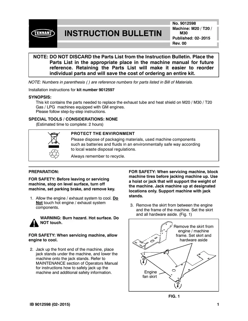
Tennant M20 instruction bulletin 9012598, page 1 of 5
Page 1 of 5 SES ref PF-R5DA-J7WD‌‌​⁠‍‍‌​‌​‍‌⁠‌⁠​⁠‌‌⁠⁠​⁠‌​​‌‍​​​‌​‍‌​​​⁠‍‌​‍‍⁠‌‌‍​⁠⁠‌‍‍⁠⁠‍⁠​‍
Text of this page
INSTRUCTION B NOTE: DO NOT DISCARD the Parts List Parts List in the appropriate pla reference. Retaining the Parts individual parts and will save the NOTE: Numbers in parenthesis ( ) are reference num Installation instructions for kit number TN4024992 SYNOPSIS: This kit contains the parts needed to replace the e Gas / LPG machines equipped with GM engines. Please follow step-by-step instructions. SPECIAL TOOLS / CONSIDERATIONS: NONE (Estimated time to complete: 2 hours) PROTECT THE ENVIRONM Please dispose of packaging such as batteries and fluids i to local waste disposal regula Always remember to recycle. PREPARATION: FOR SAFETY: Before leaving or servicing machine, stop on level surface, turn off machine, set parking brake, and remove key. 1. Allow the engine / exhaust system to cool. Do Not touch hot engine / exhaust system components. WARNING: Burn hazard. Hot surface. Do NOT touch. FOR SAFETY: When servicing machine, allow engine to cool. 2. Jack up the front end of the machine, place jack stands under the machine, and lower the machine onto the jack stands. Refer to MAINTENANCE section of Operators Manual for instructions how to safely jack up the machine and additional safety information. IB 9012598 (02- 2015) No. 9012598 Machine: M20 / T20 / BULLETIN M30 Published: 02- 2015 Rev. 00 from the Instruction Bulletin. Place the ace in the machine manual for future s List will make it easier to reorder e cost of ordering an entire kit. mbers for parts listed in Bill of Materials. exhaust tube and heat shield on M20 / M30 / T20 . MENT g materials, used machine components in an environmentally safe way according ations. . FOR SAFETY: When servicing machine, block machine tires before jacking machine up. Use a hoist or jack that will support the weight of the machine. Jack machine up at designated locations only. Support machine with jack stands. 3. Remove the skirt from between the engine and the frame of the machine. Set the skirt and all hardware aside. (Fig. 1) Remove the skirt from engine / machine frame. Set skirt and hardware aside Engine fan skirt FIG. 1 1
Tennant M20 instruction bulletin 9012598, page 2 of 5
Page 2 of 5
Text of this page
INSTALLATION: 1. Disconnect the oxygen sensor from the exhaust pipe. (Fig. 2) 2. Remove the existing exhaust pipe and heat shield from the machine. (Fig. 2) Disconnect oxygen sensor from exhaust pipe Set both M10 hex Discard gasket screws and flat washers aside Do Not remove M10 studs from engine. Leave both installed Set both M10 hex screws and Belleville washers aside Muffler Remove heat shield from exhaust system. Discard heat shield, muffler clamp, and hardware Disconnect exhaust pipe from engine and muffler. Discard exhaust pipe, gasket, and hardware FIG. 2 2 IB 9012598 (02- 2015)
Tennant M20 instruction bulletin 9012598, page 3 of 5
Page 3 of 5
Text of this page
3. Drill a 11/32 in. (222.25 mm) hole into the frame of the machine. (Fig. 3) IB 9012598 (02- 2015) .ni57.8 Front o 11/32 in. dia. (8.7312 mm) FIG 3 .ni57.8 )mm52.222( of machine Front of machine G. 3
Tennant M20 instruction bulletin 9012598, page 4 of 5
Page 4 of 5
Text of this page
13 14 8 8 13 14 13 7 12 5 6 4 Muffler FIG 4. Place one gasket (2) onto the new exhaust tube (1) and use saved hardware to connect the exhaust tube to the engine. (Fig. 4) 4 2 Oxygen sensor 15 3 2 10 1 11 16 11 3 9 2 17 FRONT G. 4 5. Use two flange nuts (11) to install the hanger (6) onto the muffler mounting bracket (4). Do not completely tighten the flange nuts. The flange nuts are tightened during final adjustment. (Fig. 4) IB 9012598 (02- 2015)
Tennant M20 instruction bulletin 9012598, page 5 of 5
Page 5 of 5
Text of this page
6. Use one M8 hex screw (12), two flat washers (13), and one M8 hex lock hex nut (14) to install the mounting angle (8) onto the frame of the machine. (Fig. 4) 7. Use one M8 hex screw (15), two flat washers (13), one sleeve (7), and one M8 hex lock hex nut (14) to install the rubber isolator (5) onto the mounting angle (8). (Fig. 4) 8. Install the hanger (6) into the rubber isolator (5). (Fig. 4) 9. Adjust the hanger (6) in the muffler mounting bracket (4) for the height where the exhaust tube (1) will be installed onto the muffler. (Fig. 4) 10. Place the remaining gasket (2) between the exhaust tube (1) and muffler and use two M10 hex screws (16) and two M10 hex nuts (17) to connect the exhaust tube and muffler mounting bracket (4) to the muffler. (Fig. 4) Bill Of Materials For Pipe Kit, Exhau Tennant Ref. Part No. Description o TN4024992 ) Pipe Kit, Exhaust, Replm Y 1 TN4044741 Tube Wldt, Exhaust, 1.6D Y 2 TN4036679 Gasket, Exhaust, .07, 1.6 Y 3 TN4044492 Shield, Heat Y 4 TN4044612 Bracket, Mtg, Muffler [M2 Y 5 TN4037292 ) Isolator, Rbr Y 6 TN4037297 Rod, Hanger, Isolator Y 7 TN4040603 Sleeve, P/M, 0.32B 0.50D Y 8 TN4211062 Angle, Mtg, Stl, .19 1.3 1 Y 9 TN4041828 Screw, Hex, M8 X 1.25 X Y 10 TN4034136 ) Washer, Flat, 0.25, Std Y 11 TN4035729 Nut, Hex, Flng, .38- 16 Y 12 TN4041992 Screw, Hex, M8 X 1.25 X Y 13 TN4042902 Washer, Flat, 0.38B 0.88 Y 14 TN4041929 Nut, Hex, Lock, M8 X 1.2 Y 15 TN4040607 ) Screw, Hex, M8 X 1.25 X Y 16 TN4019761 Screw, Hex, M10 X 1.50 Y 17 TN4041626 Nut, Hex, Stover, M10 X TENNANT P. O. Bo Minneapolis, M IB 9012598 (02- 2015) 11. Check adjustment of hanger (6) in the muffler mounting bracket (4) and make necessary adjustments. Tighten the flange nuts (11). (Fig. 4) 12. Connect the oxygen sensor to the exhaust tube (1). (Fig. 4) 13. Use saved hardware and one M8 hex screw and one flat washer (10) to install the heat shield (3) over the exhaust tube (1) and onto the engine. (Fig. 4) 14. Reinstall the skirt between the engine and the frame of the machine. 15. Lift the machine from the jack stands, remove the jack stands from under the machine, and lower the machine to the floor. 16. Start and test the machine. Observe the area around the exhaust tube and muffler for exhaust leaks. ust, Replmt [M20,T20,M30] - TN4024992 Qty. mt [M20,T20,M30] 1 D, 2 Hole Flng 1 63ID, 2/3.4BC 2 1 20/T20 2007] 1 1 1 D 0.9L [430SS] 1 1.3 01.0L 1Hole 1 X 16, 8.8 1 1 2 X 20, SS 1 8D .08, SS 4 25, NL, SS 2 X 45, SS 1 X 40, 8.8 2 1.50 2 COMPANY ox 1452 MN 55440-1452 5

Hose Kit, Coolant, Replmt [Mitsubishi]

Tennant instruction bulletin 9010906 rev. 00Published 12-2014Kit 9010904

What it’s for: Replace the lower coolant hose on M20 / M30 / T20 machines equipped with Mitsubishi engines.

  • Machines: M20, M30, T20
  • M20: all
  • Power: Gasoline, LPG
  • Engine: Mitsubishi
  • Applies to: Mitsubishi engine

Time: 2 hours · Special tools: NONE

Safety warnings (from the bulletin, word for word)

  • FOR SAFETY: Before leaving or servicing machine, stop on level surface, turn off machine, set parking brake, and remove key.

Parts

Parts for Tennant instruction bulletin 9010906
ItemPart numberQtyDescriptionPrice
TN4027830Old # 90109041Hose Kit, Coolant, Replmt [Mitsubishi]Kit$41.60/EA
1TN4182525Old # 10707311Hose, Coolant, Lower, Mold [MIT2013]Call for availability 800-440-6723

Bulletin PDF: Sign in to view or downloadSign in to download

Installation instructions (3 pages)
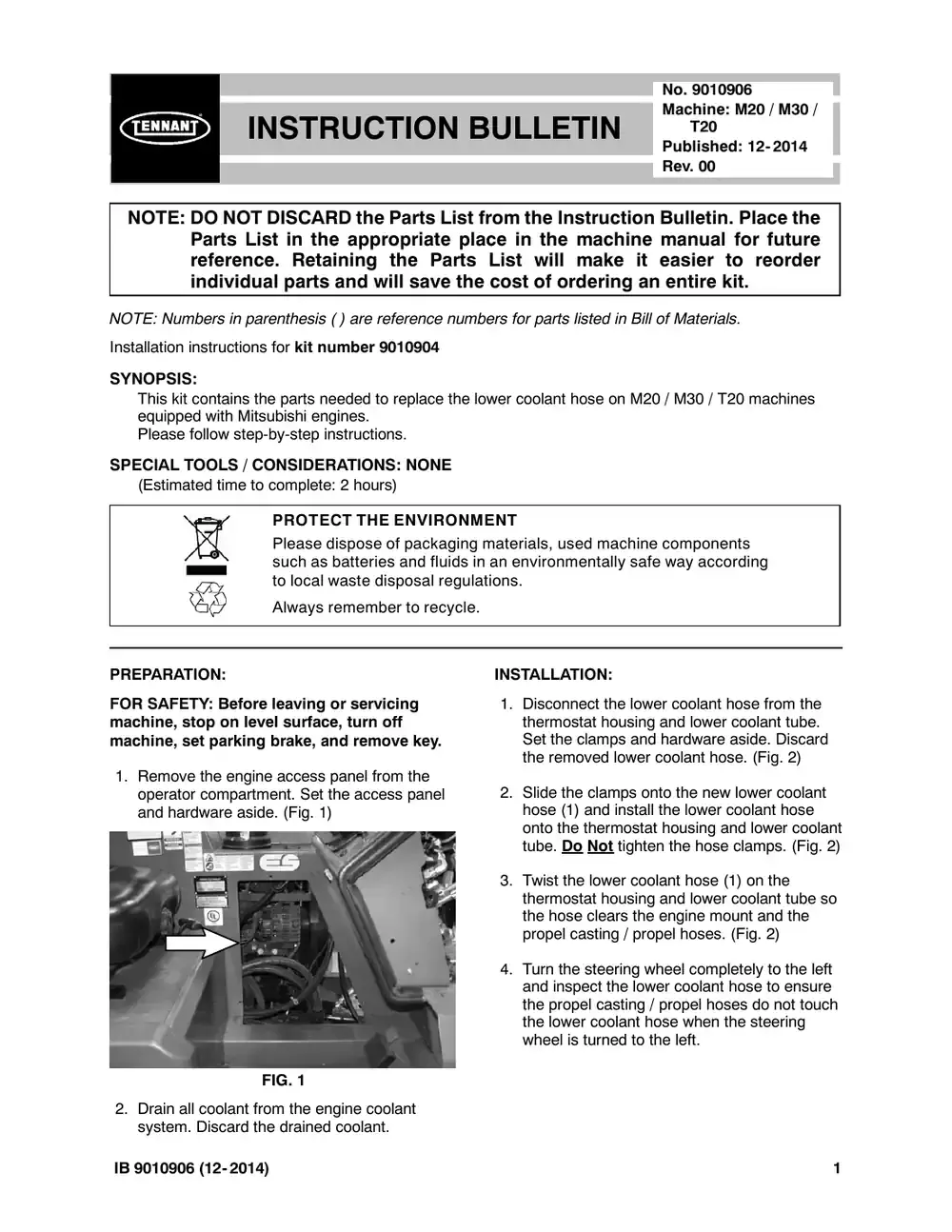
Tennant M20 instruction bulletin 9010906, page 1 of 3
Page 1 of 3 SES ref PF-W55S-G2HO‌‌​⁠‍‍‌​‌​‍‌⁠‌⁠​⁠‌‌⁠‌‍‍‍‍‍‌⁠​​​‌​‍‌​‌‌‌‌​‍​‌‌​‌⁠‍⁠⁠‍⁠⁠⁠​‍‌‌​
Text of this page
INSTRUCTION B NOTE: DO NOT DISCARD the Parts List Parts List in the appropriate pla reference. Retaining the Parts individual parts and will save the NOTE: Numbers in parenthesis ( ) are reference num Installation instructions for kit number TN4027830 SYNOPSIS: This kit contains the parts needed to replace the l equipped with Mitsubishi engines. Please follow step-by-step instructions. SPECIAL TOOLS / CONSIDERATIONS: NONE (Estimated time to complete: 2 hours) PROTECT THE ENVIRONM Please dispose of packaging such as batteries and fluids i to local waste disposal regula Always remember to recycle. PREPARATION: FOR SAFETY: Before leaving or servicing machine, stop on level surface, turn off machine, set parking brake, and remove key. 1. Remove the engine access panel from the operator compartment. Set the access panel and hardware aside. (Fig. 1) FIG. 1 2. Drain all coolant from the engine coolant system. Discard the drained coolant. IB 9010906 (12- 2014) No. 9010906 Machine: M20 / M30 / BULLETIN T20 Published: 12- 2014 Rev. 00 from the Instruction Bulletin. Place the ace in the machine manual for future s List will make it easier to reorder e cost of ordering an entire kit. mbers for parts listed in Bill of Materials. lower coolant hose on M20 / M30 / T20 machines MENT g materials, used machine components in an environmentally safe way according ations. . INSTALLATION: 1. Disconnect the lower coolant hose from the thermostat housing and lower coolant tube. Set the clamps and hardware aside. Discard the removed lower coolant hose. (Fig. 2) 2. Slide the clamps onto the new lower coolant hose (1) and install the lower coolant hose onto the thermostat housing and lower coolant tube. Do Not tighten the hose clamps. (Fig. 2) 3. Twist the lower coolant hose (1) on the thermostat housing and lower coolant tube so the hose clears the engine mount and the propel casting / propel hoses. (Fig. 2) 4. Turn the steering wheel completely to the left and inspect the lower coolant hose to ensure the propel casting / propel hoses do not touch the lower coolant hose when the steering wheel is turned to the left. 1
Tennant M20 instruction bulletin 9010906, page 2 of 3
Page 2 of 3
Text of this page
5. If necessary, adjust the position of the lower coolant hose so the propel casting / propel hoses do not touch the lower coolant hose (1) when the steering wheel is turned to the left. 6. Tighten both hose clamps to secure the lower coolant hose (1) to the thermostat housing and the lower coolant tube. (Fig. 2) 7. Reinstall the clamp onto the engine mounting bracket to secure the lower coolant hose (1) into place. (Fig. 2) Thermostat housing Set hose clamp aside Set clamp and hardware aside Lower coolant tube S cla FIG 2 8. Refill the coolant system with fresh coolant. 9. Start the machine and recheck the coolant level. Add coolant as necessary. 10. Inspect the lower coolant hose connections for leaks. Tighten clamps as necessary to eliminate leaks. 11. Reinstall the access panel into the operator compartment. Replace existing lower coolant hose with new lower coolant hose (1). Twist lower coolant hose so it clears engine mount / propel casting / propel hoses. Engine mounting bracket Set hose amp aside G. 2 IB 9010906 (12- 2014)
Tennant M20 instruction bulletin 9010906, page 3 of 3
Page 3 of 3
Text of this page
Bill Of Materials For Hose Kit, Coolant, Replmt [Mitsubishi] - TN4027830 Tennant Ref. Part No. Description Qty. o TN4027830 ) Hose Kit, Coolant, Replmt [Mitsubishi] 1 Y 1 TN4182525 Hose, Coolant, Lower, Mold [MIT2013] 1 TENNANT COMPANY P. O. Box 1452 Minneapolis, MN 55440-1452 IB 9010906 (12- 2014) 3

Tube Wldt Kit, OHG, LH, Replmt

Tennant instruction bulletin 9009517 rev. 00Published 07-2015Kit 9009516

What it’s for: Replace the left overhead guard tube on M20 / T20 / M30 machines.

  • Machines: M10, M20, M30, T20
  • M20: all
  • Power: gasoline, LPG and diesel
  • Applies to: overhead guard

Time: 1 hour · Special tools: NONE

Safety warnings (from the bulletin, word for word)

  • FOR SAFETY: Before leaving or servicing machine, stop on level surface, set parking brake, turn off machine, and remove key.

Parts

Parts for Tennant instruction bulletin 9009517
ItemPart numberQtyDescriptionPrice
TN4199593Old # 90095161Tube Wldt Kit, OHG, LH, ReplmtKitCall for availability 800-440-6723
1TN4030100Old # 10692411Tube Wldt, Leg, OHG, LH$299.68/EA
2TN4019758Old # 392831Screw, Hex, M10 X 1.50 X 25, 8.8$3.30/EA
3TN4034138Old # 324922Washer, Flat, 0.38, Std$2.50/EA
4TN4041606Old # 077921Nut, Hex, Flng, M10 X 1.50Call for availability 800-440-6723

Bulletin PDF: Sign in to view or downloadSign in to download

Installation instructions (4 pages)
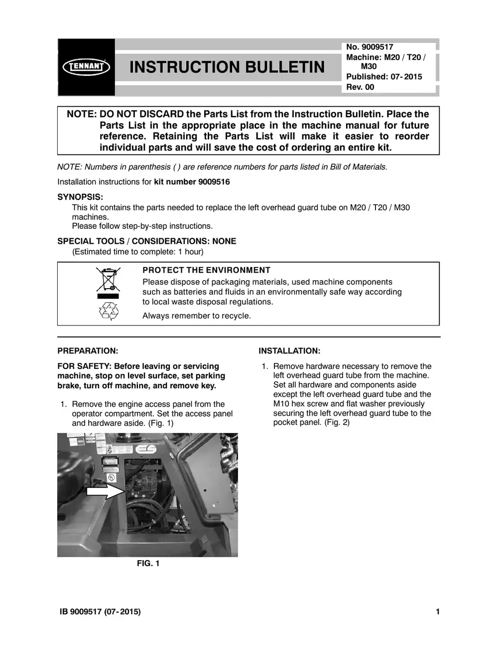
Tennant M20 instruction bulletin 9009517, page 1 of 4
Page 1 of 4 SES ref PF-6ESK-PFTL‌‌​⁠‍‍‌​‌​‍‌⁠‌⁠​⁠‌‌⁠⁠⁠‌​​‍⁠‍​​​‌​‍‌​​‌‍​⁠‌‍‍‍‍​⁠‍​‍​‍​‍​⁠‌⁠‍
Text of this page
INSTRUCTION B NOTE: DO NOT DISCARD the Parts List Parts List in the appropriate pla reference. Retaining the Parts individual parts and will save the NOTE: Numbers in parenthesis ( ) are reference num Installation instructions for kit number TN4199593 SYNOPSIS: This kit contains the parts needed to replace the l machines. Please follow step-by-step instructions. SPECIAL TOOLS / CONSIDERATIONS: NONE (Estimated time to complete: 1 hour) PROTECT THE ENVIRONM Please dispose of packaging such as batteries and fluids i to local waste disposal regula Always remember to recycle. PREPARATION: FOR SAFETY: Before leaving or servicing machine, stop on level surface, set parking brake, turn off machine, and remove key. 1. Remove the engine access panel from the operator compartment. Set the access panel and hardware aside. (Fig. 1) FIG. 1 IB 9009517 (07- 2015) No. 9009517 Machine: M20 / T20 / BULLETIN M30 Published: 07- 2015 Rev. 00 from the Instruction Bulletin. Place the ace in the machine manual for future s List will make it easier to reorder e cost of ordering an entire kit. mbers for parts listed in Bill of Materials. left overhead guard tube on M20 / T20 / M30 MENT g materials, used machine components in an environmentally safe way according ations. . INSTALLATION: 1. Remove hardware necessary to remove the left overhead guard tube from the machine. Set all hardware and components aside except the left overhead guard tube and the M10 hex screw and flat washer previously securing the left overhead guard tube to the pocket panel. (Fig. 2) 1
Tennant M20 instruction bulletin 9009517, page 2 of 4
Page 2 of 4
Text of this page
Overhead guard top Remove and set components and hardware aside Remove and discard left overhead guard tube FIG 2 Remove and set hardware aside Remove and set hardware aside Remove and discard M10 hex screw and flat washer G. 2 IB 9009517 (07- 2015)
Tennant M20 instruction bulletin 9009517, page 3 of 4
Page 3 of 4
Text of this page
1 2 3 3 4 FIG. 3 IB 9009517 (07- 2015) 3
Tennant M20 instruction bulletin 9009517, page 4 of 4
Page 4 of 4
Text of this page
FIG 2. Drill a 0.547 in. (13.90 mm) hole into the pocket panel. (Fig. 4) 3. Use saved hardware and the M10 hex screw (2), two flat washers (3), and the M10 hex nut (4) to install the left overhead guard tube (1) onto the machine. (Fig. 3) 4. Reinstall the engine access panel into the operator compartment. (Fig. 1) Bill Of Materials For Tube Wldt K Tennant Ref. Part No. Description 1 TN4030100 ) Tube Wldt, Leg, OHG, LH 2 TN4019758 Screw, Hex, M10 X 1.50 3 TN4034138 Washer, Flat, 0.38, Std 4 TN4041606 Nut, Hex, Flng, M10 X 1. TENNANT P. O. Bo Minneapolis, M 4 G. 4 Kit, OHG, LH, Replmt - TN4199593 Qty. H 1 X 25, 8.8 1 2 .50 1 COMPANY ox 1452 MN 55440-1452 IB 9009517 (07- 2015)

Pump Kit, Mtg, Aux, CI [M20 & T20]

Tennant instruction bulletin 9007144 rev. 01Published 08-2015Kit 9007142, 9007143

What it’s for: Replace the auxiliary hydraulic pump on M20 (serial numbers 000000- 003297), T20 (serial numbers 000000- 002282), and M30 (serial numbers 000000- 001462) machines.

  • Machines: M20, M30, T20
  • M20 SN 000000–003297
  • Power: gasoline, LPG and diesel
  • Applies to: lights

Time: 2 hours · Special tools: NONE

Safety warnings (from the bulletin, word for word)

  • FOR SAFETY: Before leaving or servicing machine, stop on level surface, turn off machine, and remove key.

Parts

Parts for Tennant instruction bulletin 9007144
ItemPart numberQtyDescriptionPrice
TN4011841Old # 90071421Pump Kit, Mtg, Aux, CI [M20 & T20]Kit$1,593.60/EA
TN4011842Old # 90071431OM10 1 Y 3 65245- 1 Seal, Org, .069 X 3.06ID 1 Bill Of Materials For Pump Kit, Mtg, Aux, CI [M30]KitCall for availability 800-440-6723
1TN4186836Old # 10591951Pump, Hyd, Gear, Ext, 3, 00.97 2500, CWCall for availability 800-440-6723
2TN4013874Old # 475131Fitting, Hyd, E45, JM08 / OM10$34.20/EA
1TN4186837Old # 10591961Pump, Hyd, Gear, Ext, 3, 00.85 2500, CWCall for availability 800-440-6723
2TN4013874Old # 475131Fitting, Hyd, E45, JM08 / OM10$34.20/EA

Bulletin PDF: Sign in to view or downloadSign in to download

Installation instructions (4 pages)
Tennant M20 instruction bulletin 9007144, page 1 of 4
Page 1 of 4 SES ref PF-2UAF-IQBG‌‌​⁠‍‍‌​‌​‍‌⁠‌⁠​⁠‌‌⁠‍​⁠‍​⁠⁠‍​​​‌​‍‌​‌⁠‌‍⁠‌⁠‍‍⁠​​‌​​‌⁠‍‍‍‍⁠⁠‌
Text of this page
INSTRUCTION NOTE: DO NOT DISCARD the Parts List Parts List in the appropriate pla reference. Retaining the Parts individual parts and will save the NOTE: Numbers in parenthesis ( ) are reference num Installation instructions for kit number TN4011841 (M20 SYNOPSIS: This kit contains the parts needed to replace the a 000000- 003297), T20 (serial numbers 000000- 00 machines. Please follow step-by-step instructions. SPECIAL TOOLS / CONSIDERATIONS: NONE (Estimated time to complete: 2 hours) When assembling/disassembling hydraulic comp 1. Thoroughly clean outside of hydraulic component and flush hoses and fittings with air, solvent, or hy ports to prevent contaminants from entering syste 2. Mark hydraulic hoses with locations of where they reconnect hoses to proper locations. 3. Discard all hydraulic fluid drained from the system hydraulic reservoir. Hydraulic fluid is potentially da and local laws/regulations governing the disposal disposing hydraulic fluid. PROTECT THE ENVIRONM Please dispose of packaging such as batteries and fluids i to local waste disposal regula Always remember to recycle. PREPARATION: 1. Park the machine on a clean level surface, turn off the machine, remove the key, and set the parking brake. FOR SAFETY: Before leaving or servicing machine, stop on level surface, turn off machine, and remove key. IB 9007144 (08- 2015) No. 9007144 Machine: M20, T20, N BULLETIN M30 Published: 08- 2015 Rev. 01 from the Instruction Bulletin. Place the ace in the machine manual for future s List will make it easier to reorder e cost of ordering an entire kit. mbers for parts listed in Bill of Materials. 0 & T20) / TN4011842 (M30) auxiliary hydraulic pump on M20 (serial numbers 02282), and M30 (serial numbers 000000- 001462) ponents: ts before disconnecting hydraulic hoses or fittings ydraulic fluid and cap disconnected hoses or open em. y are connected. Markings make it easier to m. Use only new approved hydraulic fluid to replenish angerous to the environment. Obey all federal, state, of environmentally hazardous materials when MENT g materials, used machine components in an environmentally safe way according ations. . 2. Open or remove the engine cover. 3. Remove any components / rearrange hoses necessary to make access to the hydraulic gear pump easier. 1
Tennant M20 instruction bulletin 9007144, page 2 of 4
Page 2 of 4
Text of this page
INSTALLATION: From steering valve From t- fitting on vacuum fan motor From port P2 on scrub valve Auxiliary hydraulic pump O- ring F Hydraulic hy propel res pump FIG 1. Disconnect all the hydraulic hoses from the auxiliary hydraulic pump on the hydraulic propel pump. (Fig. 1) 2. Remove the auxiliary hydraulic pump from the hydraulic propel pump. Discard the auxiliary hydraulic pump and o- ring. (Fig. 1) 3. Disconnect the 90_ fitting from the hose connected to the t- fitting on the vacuum fan motor. Discard the 90_ fitting. (Fig. 1) 4. Install the 45_ fitting (2) onto the hose from the t- fitting on the vacuum fan motor. (Fig. 1) 5. Apply a light coat of grease onto the o- ring (3). 6. Install the new o- ring (3) into the new auxiliary hydraulic pump (3). Refer to Fig. 1. 7. Install the new auxiliary hydraulic pump (2) onto the hydraulic propel pump. Take care to not damage the o- ring (3) when installing the auxiliary hydraulic pump onto the hydraulic propel pump. (Fig. 1) 2 If equipped with 90_ hydraulic fitting, remove and discard 90_ hydraulic fitting. Replace with 45_ hydraulic fitting (2) Remove and discard auxiliary hydraulic pump and o- ring. Replace with new auxiliary hydraulic pump (1) and o- ring (3) From ydraulic servoir G. 1 8. Install the hose connected to the t- fitting on the vacuum fan motor to the first stage on the auxiliary hydraulic pump (1). (Fig.1 / Fig. 2) 9. Connect the hose from port P2 on the scrub valve to the second stage on the auxiliary hydraulic pump (1). (Fig.1 / Fig. 2) 10. Connect the hoses from the hydraulic reservoir and front wheel drive motor to the auxiliary hydraulic pump (1). (Fig. 1 / Fig. 2) 11. Reinstall any components removed to make installing the new auxiliary hydraulic pump (1) easier. (Fig. 1) 12. Replenish the hydraulic system with fresh hydraulic fluid. 13. Start and test the machine. Observe for hydraulic leaks around areas where hydraulic connections were broken, moved, or components replaced. IB 9007144 (08- 2015)
Tennant M20 instruction bulletin 9007144, page 3 of 4
Page 3 of 4
Text of this page
P Vacuum fan motor (scrub) 2 First stage FIG IB 9007144 (08- 2015) P1 Scrub valve P2 From steering valve 1 Second stage From hydraulic reservoir G. 2 3
Tennant M20 instruction bulletin 9007144, page 4 of 4
Page 4 of 4
Text of this page
Bill Of Materials For Pump Kit, Mt Tennant Ref. Part No. Description o TN4011841 ) Pump Kit, Mtg, Aux, CI [M Y 1 TN4186836 Pump, Hyd, Gear, Ext, 3, Y 2 TN4013874 Fitting, Hyd, E45, JM08 / Y 3 65245- 1 Seal, Org, .069 X 3.06ID Bill Of Materials For Pump Kit, Tennant Ref. Part No. Description o TN4011842 ) Pump Kit, Mtg, Aux, CI [M Y 1 TN4186837 Pump, Hyd, Gear, Ext, 3, Y 2 TN4013874 Fitting, Hyd, E45, JM08 / Y 3 65245- 1 Seal, Org, .069 X 3.06ID TENNANT P. O. Bo Minneapolis, M 4 tg, Aux, CI [M20 & T20] - TN4011841 Qty. M20 & T20] 1 , 00.97 2500, CW 1 / OM10 1 1 , Mtg, Aux, CI [M30] - TN4011842 Qty. M30] 1 , 00.85 2500, CW 1 / OM10 1 1 COMPANY ox 1452 MN 55440-1452 IB 9007144 (08- 2015)

Motor Kit, Replmt [M20 & T20]

Tennant instruction bulletin 340854 rev. 02Published 12-2015Kit 9003461

What it’s for: Replace scrub vacuum fan motor on M20 (Serial Numbers 000000- 006877) and T20 (Serial Numbers 000000- 005892) machines.

  • Machines: M20, T20
  • M20 SN 000000–006877
  • Power: gasoline, LPG and diesel

Time: 5- 7 hours (5 hours if hydraulic system is vacuumed down, 7 hours if hydraulic fluid is removed · Special tools: (Estimated time to complete: 5- 7 hours (5 hours i hydraulic fluid is removed)) 1. Thoroughly clean outside of hydraulic component and flush hoses and fittings with air, solvent, or hy ports to prevent contaminants from entering syste 2. Mark hydraulic hoses with locations of where they hoses to proper locations. 3. Discard all hydraulic fluid drained from the system hydraulic reservoir. Hydraulic fluid is potentially da and local laws/regulations governing the disposal disposing hydraulic fluid. PROTECT THE ENVIRONM Please dispose of packaging such as batteries and fluids i to local waste disposal regula Always remember to recycle.

Safety warnings (from the bulletin, word for word)

  • FOR SAFETY: Before leaving or servicing machine, stop on level surface, turn off machine, and remove key.
  • WARNING: Always disconnect battery cables from machine before working on electrical components. NOTE: Do not discard removed parts unless instructed to do so. Most parts are reinstalled after the scrub vacuum fan is replaced.

Parts

Parts for Tennant instruction bulletin 340854
ItemPart numberQtyDescriptionPrice
TN4016739Old # 90034611Motor Kit, Replmt [M20 & T20]Kit$658.80/EA
1TN4030527Old # 10712521Motor, Hyd, Gear, Ext 0.13 LH 3000Call for availability 800-440-6723
2TN4041602Old # 077881Nut, Hex, Std, M12 x 1.75, SS$3.40/EA
3TN4028682Old # 548614Screw, Flt, .38- 16 X 1.50 Al$0.55/EA
4TN4037922Old # 10145634Washer, Flat, 0.40B 1.12D .12, SS$5.80/EA
5TN4028758Old # 366434Nut, Hex. Lock, .38- 16, NL, Thin$2.50/EA
6TN4015802Old # 395344Screw, Flat, .25- 20 X 1.00, Alm$3.20/EA
7TN4034654Old # 329814Nut, Hex, Lock, .25- 20, Nl$2.50/EA
8TN4015364Old # 542744Isolator, Vib, Bshg, 1.1D 0.6L .4B 0.78H$14.70/EA
9TN4000354Old # 10385732Block, Fan, Scrub, Field KitCall for availability 800-440-6723
10TN4011921Old # 763151Fitting, Hyd, Tee, JF08/JM08/JM08, Br$15.10/EA
11TN4013874Old # 475131Fitting, Hyd, E45, JM08/OM10$34.20/EA
12TN4025261Old # 770981Fitting, Hyd, E90, JM06/OM04$15.50/EA
13TN4029146Old # 566921Fitting, Hyd, Str, JM08/OM10$10.60/EA
14TN4030456Old # 363281Washer, Flat, Belleville, .50$4.10/EA

Bulletin PDF: Sign in to view or downloadSign in to download

Installation instructions (11 pages)
Tennant M20 instruction bulletin 340854, page 1 of 11
Page 1 of 11 SES ref PF-ZXOS-TVQB‌‌​⁠‍‍‌​‌​‍‌⁠‌⁠​⁠‌‌⁠⁠​⁠‌​​‌​​​​‌​‍‌​‌‌‍‍⁠‍‌‌‍‍‍‌‌​​​‍​‌‌‍⁠‍‍
Text of this page
INSTRUCTION NOTE: DO NOT DISCARD the Parts List Parts List in the appropriate pla reference. Retaining the Parts individual parts and will save the NOTE: Numbers in parenthesis ( ) are reference num Installation instructions for kit number TN4016739 SYNOPSIS: This kit contains the parts needed to replace scru 000000- 006877) and T20 (Serial Numbers 00000 Please follow step-by-step instructions. SPECIAL TOOLS / CONSIDERATIONS: (Estimated time to complete: 5- 7 hours (5 hours i hydraulic fluid is removed)) 1. Thoroughly clean outside of hydraulic component and flush hoses and fittings with air, solvent, or hy ports to prevent contaminants from entering syste 2. Mark hydraulic hoses with locations of where they hoses to proper locations. 3. Discard all hydraulic fluid drained from the system hydraulic reservoir. Hydraulic fluid is potentially da and local laws/regulations governing the disposal disposing hydraulic fluid. PROTECT THE ENVIRONM Please dispose of packaging such as batteries and fluids i to local waste disposal regula Always remember to recycle. PREPARATION: 1. Park the machine on a clean level surface , turn off the machine, engage the parking brake, and remove the key. FOR SAFETY: Before leaving or servicing machine, stop on level surface, turn off machine, and remove key. IB 340854 (12- 2015) No. 340854 Machine: M20 / T20 N BULLETIN Published: 12- 2015 Rev. 02 from the Instruction Bulletin. Place the ace in the machine manual for future s List will make it easier to reorder e cost of ordering an entire kit. mbers for parts listed in Bill of Materials. ub vacuum fan motor on M20 (Serial Numbers 00- 005892) machines. if hydraulic system is vacuumed down, 7 hours if ts before disconnecting hydraulic hoses or fittings ydraulic fluid and cap disconnected hoses or open em. y are attached. Markings make it easier to reconnect m. Use only new approved hydraulic fluid to replenish angerous to the environment. Obey all federal, state, of environmentally hazardous materials when MENT g materials, used machine components in an environmentally safe way according ations. . 2. Disconnect the battery cables from the battery. WARNING: Always disconnect battery cables from machine before working on electrical components. NOTE: Do not discard removed parts unless instructed to do so. Most parts are reinstalled after the scrub vacuum fan is replaced. 3. Remove the engine cover from the machine. Set the engine cover aside. 1
Tennant M20 instruction bulletin 340854, page 2 of 11
Page 2 of 11
Text of this page
4. Remove the coolant reservoir from the bracket and move the reservoir away from the scrub vacuum fan. (Fig. 1) NOTE: If necessary, unplug spark plug cables before moving the coolant reservoir. FIG. 1 5. Remove the hardware holding the air cleaner bracket to the machine and move the air cleaner/air cleaner bracket away from the scrub vacuum fan. (Fig. 2) FIG. 2 6. Drain hydraulic fluid from the system. NOTE: It is not necessary to drain hydraulic fluid if a hydraulic vacuum is used to vacuum down the hydraulic system. 2 INSTALLATION: 1. M20 machines serial numbers 000000 - 002699 only: Disconnect both steel tubes from the lower valve. (Fig. 3) FIG. 3 2. Disconnect the hose attached to location P1 on the scrub valve. (Fig. 4) FIG. 4 3. Disconnect all main wire harness leads from the scrub valve. 4. Remove the support bracket. Set the support bracket and hardware aside. (Fig. 5) FIG. 5 IB 340854 (12- 2015)
Tennant M20 instruction bulletin 340854, page 3 of 11
Page 3 of 11
Text of this page
5. Loosen the hardware holding the scrub valve bracket to the solution tank. (Fig. 6) FIG. 6 6. Lift the scrub valve assembly up from the hardware and away from the solution tank. (Fig. 7) FIG. 7 7. Disconnect the intake hose from the sweep fan. Move the intake hose away from the scrub vacuum fan. Set the hose clamp aside. (Fig. 8) FIG. 8 IB 340854 (12- 2015) 8. Disconnect the four hydraulic hoses (A), (B), (C), and (D) from the fittings on the scrub fan motor. (Fig. 9) A B D C Scrub Fan Motor FIG. 9 NOTE: If working on an LP machine, the fuel tank can be removed to make access to scrub vacuum fan easier. Refer to Operators Manual for instructions how to remove LP tank. NOTE: If working on a diesel or gasoline machine without FaST, ES, or spray hose options, the operator station removable panel can be removed to make access to scrub fan easier. Set the panel and hardware aside. (Fig. 10) FIG. 10 3
Tennant M20 instruction bulletin 340854, page 4 of 11
Page 4 of 11
Text of this page
9. Remove the hardware holding the scrub vacuum fan to the solution tank. Set the hardware aside. (Fig. 11) Solution Tank Set aside Set aside FIG. 11 10. Disconnect the hose from the scrub vacuum fan. Set the hose clamp aside. (Fig. 12) FIG. 12 11. Remove the scrub vacuum fan from the machine. (Fig. 12) 12. Cut the silicone sealant from around the scrub vacuum fan. (Fig. 13) FIG. 13 4 13. Use a marker to mark the positions of the vacuum fan opening and brackets onto the scrub vacuum fan housing. (Fig. 14) FIG. 14 14. Remove the hardware holding the brackets onto the scrubber vacuum fan and the hardware holding the front housing to the scrubber vacuum fan housing. Set all hardware and brackets aside. (Fig. 15) FIG. 15 15. Remove the front housing from the scrubber vacuum fan housing. Set the front housing aside. (Fig. 16) FIG. 16 IB 340854 (12- 2015)
Tennant M20 instruction bulletin 340854, page 5 of 11
Page 5 of 11
Text of this page
16. Remove the crown nut holding the impeller onto the hydraulic motor. Discard the crown nut. (Fig. 17) FIG. 17 17. Pry the impeller from the scrubber vacuum fan and set the impeller aside. Discard the motor key. (Fig. 18 / Fig. 23) FIG. 18 18. Remove six shims (three thin and three thick) from the scrubber vacuum fan. Set shims aside. (Fig. 19 / Fig. 23) FIG. 19 IB 340854 (12- 2015) 19. Use a marker to mark the positions of the hydraulic motor fittings onto the scrub vacuum fan housing. (Fig. 20) FIG. 20 20. Remove and discard the four flat screws, isolator bushings, washers, and hex nuts holding the hydraulic motor assembly to the scrubber vacuum fan housing. (Fig. 21 / Fig. 23) FIG. 21 21. Remove the hydraulic motor from the motor mounting bracket. Set the bracket aside. Discard motor and hardware. (Fig. 22) FIG. 22 5
Tennant M20 instruction bulletin 340854, page 6 of 11
Page 6 of 11
Text of this page
Save scrub Save scrub vacuum fan housing Save motor mounting bracket 10* 6* 1* 12* 8* 7* 4* 5* 11* * All nu existin FIG 22. Remove the plugs from the new hydraulic motor (1). (Fig. 23 / Fig. 24) 23. Install the straight fitting (13) into the hydraulic motor (1). (Fig. 23 / Fig. 24) 24. Install the t- fitting (10) into the straight fitting (13) installed into hydraulic motor (1) in the previous step. Do not completely tighten t- fitting. The t- fitting is tightened during later adjustment. (Fig. 23 / Fig. 24) 25. Install the 90_ fitting (12) and 45_ fitting (11) into the hydraulic motor (1). Note orientation of both fittings on the hydraulic motor. (Fig. 23 / Fig. 24) 26. Use four flat screws (6) and hex nuts (7) to install the hydraulic motor (1) onto the motor mounting bracket. Torque hardware 7.6- 9.9 Nm (5.6- 7.3 ft. lbs). (Fig. 23 / Fig. 24) NOTE: Do not lose the key to the new hydraulic motor (1). Set the key aside in a safe place. 6 Save shims (Qty 6) 2* Save 3* impeller * umbered parts are included with this kit. Discard ng parts numbered parts are replacing. G. 23 27. Use four flat screws (3), isolator bushings (8), washers (4), and hex nuts (5) to install the hydraulic motor assembly from the previous step onto the scrubber vacuum fan housing. Be sure fittings on the hydraulic motor are aligned with markings on the scrub vacuum fan housing. (Fig. 23 / Fig. 24) 28. Apply a light coat of anti- seize lubricant onto the shaft of the hydraulic motor (1). 29. Install the six shims onto the hydraulic motor (1) shaft. (Fig. 23 / Fig. 24) 30. Place the impeller onto the hydraulic motor (1) shaft. (Fig. 23 / Fig. 24) 31. Insert the key to the hydraulic motor key into the slot in the shaft of the hydraulic motor (1). 32. Apply a light coat of Loctite® 242 onto the hex nut (2) threads and use the nut and belleville washer (14) to secure the impeller onto the hydraulic motor (1). (Fig. 24) Loctite® is a registered trademark of the Henkel Corporation. IB 340854 (12- 2015)
Tennant M20 instruction bulletin 340854, page 7 of 11
Page 7 of 11
Text of this page
Note: Scrub fan blocks (9) are not Shims shown in this drawing shown in this drawing (S 10 6 13 12 8 4 5 1 7 11 FIG 33. Set the scrubber vacuum fan onto the scrub fan blocks blocks (9). (Fig. 25) 9 9 FIG. 25 IB 340854 (12- 2015) S(Qhtiym6s) 2 14 Impeller 3 G. 24 7
Tennant M20 instruction bulletin 340854, page 8 of 11
Page 8 of 11
Text of this page
34. Place the vacuum fan front housing onto the scrubber vacuum fan housing and align the opening in the vacuum fan front housing and bracket locations with markings on the scrubber vacuum fan housing. (Fig. 26) FIG. 26 35. Reinstall the brackets and hardware onto the scrub vacuum fan. Be sure the vacuum fan front housing, the bottom edge of the scrubber vacuum fan housing, and the bottom edges of the brackets are aligned. (Fig. 27) FIG. 27 36. Turn the scrub vacuum fan over and clean all old silicone sealant from the scrubber vacuum fan housing and the vacuum fan front housing. 8 37. Apply the silicone sealant to the scrubber vacuum fan housing and the front vacuum fan housing. (Fig. 28) FIG. 28 38. Smooth the sealant into the groove where the scrubber vacuum fan housing and the front vacuum fan housing meet. Clean excess sealant from the scrub vacuum fan. Allow the sealant to dry for 2- 3 hours. (Fig. 29) FIG. 29 39. Clamp the sweep vacuum hose back onto the scrub vacuum fan. (Fig. 30) FIG. 30 IB 340854 (12- 2015)
Tennant M20 instruction bulletin 340854, page 9 of 11
Page 9 of 11
Text of this page
40. Reinstall the scrub vacuum fan onto the solution tank. (Fig. 31) Solution Tank FIG. 31 41. Hold hydraulic hoses (A) and (B) to the t- fitting (10) installed on the hydraulic motor (1) and note distance t- fitting must be adjusted for hose installation. (Fig. 32) 10 A B D 1 C FIG. 32 42. Adjust the t- fitting (10) as necessary to connect hydraulic hoses (A) and (B). (Fig. 32) 43. Connect hydraulic hoses (A), (B), (C), and (D) to the scrub fan motor (1). (Fig. 32) IB 340854 (12- 2015) 44. Reconnect the intake hose to the sweep fan. (Fig. 33) FIG. 33 45. Reinstall the scrub valve assembly onto the solution tank. (Fig. 34) FIG. 34 46. Reconnect the hose removed from location P1 on the scrub valve. (Fig. 35) FIG. 35 9
Tennant M20 instruction bulletin 340854, page 10 of 11
Page 10 of 11
Text of this page
47. Reconnect both steel tubes to the lower valve. (Fig. 36) FIG. 36 48. Reconnect the main wire harness leads to the scrub valve. 49. Reinstall the support bracket. (Fig. 37) FIG. 37 50. Reinstall the air cleaner assembly/air cleaner assembly bracket onto the machine. (Fig. 38) FIG. 38 10 51. Reinstall the coolant reservoir onto the bracket. (Fig. 39) FIG. 39 52. If hydraulic fluid was drained to install this kit, replenish the hydraulic system with Tennant approved hydraulic fluid. Refer to the Operators Manual for additional information. 53. Reinstall the LP tank, operator station removable panel, and other parts/ components removed to install the new vacuum fan motor kit onto the machine. 54. Reconnect the battery cables to the battery. 55. Start and test the machine. Observe the scrub vacuum fan and other hydraulic components that had fittings / hoses removed / replaced for leaks. Run the scrub vacuum fan to ensure it operates. IB 340854 (12- 2015)
Tennant M20 instruction bulletin 340854, page 11 of 11
Page 11 of 11
Text of this page
Bill of Materials for Motor Kit, Replmt [M20 & T20] - TN4016739 Tennant Ref. Part No. Description Qty. o TN4016739 ) Motor Kit, Replmt [M20 & T20] 1 Y 1 TN4030527 Motor, Hyd, Gear, Ext 0.13 LH 3000 1 Y 2 TN4041602 Nut, Hex, Std, M12 x 1.75, SS 1 Y 3 TN4028682 Screw, Flt, .38- 16 X 1.50 Al 4 Y 4 TN4037922 Washer, Flat, 0.40B 1.12D .12, SS 4 Y 5 TN4028758 Nut, Hex. Lock, .38- 16, NL, Thin 4 Y 6 TN4015802 Screw, Flat, .25- 20 X 1.00, Alm 4 Y 7 TN4034654 Nut, Hex, Lock, .25- 20, Nl 4 Y 8 TN4015364 Isolator, Vib, Bshg, 1.1D 0.6L .4B 0.78H 4 Y 9 TN4000354 Block, Fan, Scrub, Field Kit 2 Y 10 TN4011921 Fitting, Hyd, Tee, JF08/JM08/JM08, Br 1 Y 11 TN4013874 Fitting, Hyd, E45, JM08/OM10 1 Y 12 TN4025261 Fitting, Hyd, E90, JM06/OM04 1 Y 13 TN4029146 Fitting, Hyd, Str, JM08/OM10 1 Y 14 TN4030456 Washer, Flat, Belleville, .50 1 TENNANT COMPANY P. O. Box 1452 Minneapolis, MN 55440-1452 IB 340854 (12- 2015) 11

leaks. Run the scrub vacuum fan to ensure FIG. 21 it operates. Bill of Materials for Fan Kit, Scrub, Replmt [M20 & T20]

Tennant instruction bulletin 340853 rev. 03Published 12-2015Kit 9003455

What it’s for: Replace scrub vacuum fan assembly on M20 (Serial Numbers 000000- 006877) and T20 (Serial Numbers 000000- 005892) machines.

  • Machines: M20, T20
  • M20 SN 000000–006877
  • Power: gasoline, LPG and diesel

Time: 3.5 hours · Special tools: (Estimated time to complete: 3.5 hours) 1. Thoroughly clean outside of hydraulic component and flush hoses and fittings with air, solvent, or hy ports to prevent contaminants from entering syste 2. Mark hydraulic hoses with locations of where they hoses to proper locations. 3. Discard all hydraulic fluid drained from the system hydraulic reservoir. Hydraulic fluid is potentially da and local laws/regulations governing the disposal disposing hydraulic fluid. PROTECT THE ENVIRONM Please dispose of packaging such as batteries and fluids i to local waste disposal regula Always remember to recycle.

Safety warnings (from the bulletin, word for word)

  • FOR SAFETY: Before leaving or servicing machine, stop on level surface, turn off machine, and remove key.
  • WARNING: Always disconnect battery cables from machine before working on electrical components. NOTE: Do not discard removed parts unless instructed to do so. Most parts are reinstalled after the scrub vacuum fan is replaced.

Parts

Parts for Tennant instruction bulletin 340853
ItemPart numberQtyDescriptionPrice
TN4016733Old # 90034551leaks. Run the scrub vacuum fan to ensure FIG. 21 it operates. Bill of Materials for Fan Kit, Scrub, Replmt [M20 & T20]Kit$1,750.60/EA
1TN4195871Old # 10225591Housing Wldt, VacFan, RearCall for availability 800-440-6723
2TN4011921Old # 763151Fitting, Hyd, Tee, JF08/JM08/JM08, Br$15.10/EA
3TN4013874Old # 475131Fitting, Hyd, E45, JM08/OM10$34.20/EA
4TN4025261Old # 770981Fitting, Hyd, E90, JM06/OM04$15.50/EA
5TN4029146Old # 566921Fitting, Hyd, Str, JM08/OM10$10.60/EA

Bulletin PDF: Sign in to view or downloadSign in to download

Installation instructions (7 pages)
Tennant M20 instruction bulletin 340853, page 1 of 7
Page 1 of 7 SES ref PF-PGQD-JQJF‌‌​⁠‍‍‌​‌​‍‌⁠‌⁠​⁠‌‌⁠‌‌‍​‍‍‌⁠​​​‌​‍‌​‍‍‍‌​​‌‍‍⁠‍‍​‌‌​‍⁠‍​⁠‍‌‍
Text of this page
INSTRUCTION NOTE: DO NOT DISCARD the Parts List Parts List in the appropriate pla reference. Retaining the Parts individual parts and will save the NOTE: Numbers in parenthesis ( ) are reference num Installation instructions for kit number TN4016733 SYNOPSIS: This kit contains the parts needed to replace scru 000000- 006877) and T20 (Serial Numbers 00000 Please follow step-by-step instructions. SPECIAL TOOLS / CONSIDERATIONS: (Estimated time to complete: 3.5 hours) 1. Thoroughly clean outside of hydraulic component and flush hoses and fittings with air, solvent, or hy ports to prevent contaminants from entering syste 2. Mark hydraulic hoses with locations of where they hoses to proper locations. 3. Discard all hydraulic fluid drained from the system hydraulic reservoir. Hydraulic fluid is potentially da and local laws/regulations governing the disposal disposing hydraulic fluid. PROTECT THE ENVIRONM Please dispose of packaging such as batteries and fluids i to local waste disposal regula Always remember to recycle. PREPARATION: 1. Park the machine on a clean level surface and engage the parking brake. FOR SAFETY: Before leaving or servicing machine, stop on level surface, turn off machine, and remove key. IB 340853 (12- 2015) No. 340853 Machine: M20 / T20 N BULLETIN Published: 12- 2015 Rev. 03 from the Instruction Bulletin. Place the ace in the machine manual for future s List will make it easier to reorder e cost of ordering an entire kit. mbers for parts listed in Bill of Materials. ub vacuum fan assembly on M20 (Serial Numbers 00- 005892) machines. ts before disconnecting hydraulic hoses or fittings ydraulic fluid and cap disconnected hoses or open em. y are attached. Markings make it easier to reconnect m. Use only new approved hydraulic fluid to replenish angerous to the environment. Obey all federal, state, of environmentally hazardous materials when MENT g materials, used machine components in an environmentally safe way according ations. . 2. Disconnect the battery cables from the batteries. WARNING: Always disconnect battery cables from machine before working on electrical components. NOTE: Do not discard removed parts unless instructed to do so. Most parts are reinstalled after the scrub vacuum fan is replaced. 3. Remove the engine cover from the machine. Set the engine cover aside. 1
Tennant M20 instruction bulletin 340853, page 2 of 7
Page 2 of 7
Text of this page
4. Remove the coolant reservoir from the bracket and move the reservoir away from the scrub vacuum fan. (Fig. 1) NOTE: If necessary, unplug spark plug cables before moving the coolant reservoir. FIG. 1 5. Remove the hardware holding the air cleaner bracket to the machine and move the air cleaner/air cleaner bracket away from the scrub vacuum fan. (Fig. 2) FIG. 2 6. Drain hydraulic fluid from the system. NOTE: It is not necessary to drain hydraulic fluid if a hydraulic vacuum is used to vacuum down the hydraulic system. 2 INSTALLATION: 1. M20 machines serial numbers 000000 - 002699 only: Disconnect both steel tubes from the lower valve. (Fig. 3) FIG. 3 2. Disconnect the hose attached to location P1 on the scrub valve. (Fig. 4) FIG. 4 3. Disconnect all main wire harness leads from the scrub valve. 4. Remove the support bracket. Set the support bracket and hardware aside. (Fig. 5) FIG. 5 IB 340853 (12- 2015)
Tennant M20 instruction bulletin 340853, page 3 of 7
Page 3 of 7
Text of this page
5. Loosen the hardware holding the scrub valve bracket to the solution tank. (Fig. 6) FIG. 6 6. Lift the scrub valve assembly up from the hardware and away from the solution tank. (Fig. 7) FIG. 7 7. Disconnect the intake hose from the sweep fan. Move the intake hose away from the scrub vacuum fan. Set the hose clamp aside. (Fig. 8) FIG. 8 IB 340853 (12- 2015) 8. Disconnect the four hydraulic hoses (A), (B), (C), and (D) from the fittings on the scrub fan motor. (Fig. 9) A B D C Scrub Fan Motor FIG. 9 NOTE: If working on an LP machine, the fuel tank can be removed to make access to scrub vacuum fan easier. Refer to Operators Manual for instructions how to remove LP tank. NOTE: If working on a diesel or gasoline machine without FaST, ES, or spray hose options, the operator station removable panel can be removed to make access to scrub fan easier. Set the panel and hardware aside. (Fig. 10) FIG. 10 3
Tennant M20 instruction bulletin 340853, page 4 of 7
Page 4 of 7
Text of this page
9. Remove the hardware holding the scrub vacuum fan to the solution tank. Set the hardware aside. (Fig. 11) Solution Tank Set aside Set aside FIG. 11 10. Disconnect the hose from the scrub vacuum fan. Set the hose clamp aside. (Fig. 12) FIG. 12 11. Remove the scrub vacuum fan from the machine. (Fig. 12) 4 IB 340853 (12- 2015)
Tennant M20 instruction bulletin 340853, page 5 of 7
Page 5 of 7
Text of this page
NOTE: Do No 2 fan. Hydraulic fan to show or 5 4 3 Saved hardware 1 FIG 12. Remove the plugs from the new scrub vacuum fan (1) motor. (Fig. 13) 13. Install the straight fitting (5) into the vacuum fan (1) motor. (Fig. 13) 14. Install the t- fitting (2) into the straight fitting (5) installed into the scrub vacuum fan (1) motor. Do not completely tighten t- fitting. The t- fitting is tightened during later adjustment. (Fig. 13) 15. Install the 90_ fitting (4) and 45_ fitting (3) into the scrub vacuum fan (1) motor. Note orientation of both fittings on the hydraulic motor. (Fig. 13) 16. Place the new scrub vacuum fan (1) where the old scrub vacuum fan was previously installed. (Fig. 12 / Fig. 13) 17. Clamp the vacuum hose onto the scrub vacuum fan (1). (Fig. 12 / Fig. 13) 18. Use the saved hardware to install the scrub vacuum fan (1) onto the solution tank. (Fig. 13) IB 340853 (12- 2015) ot remove hydraulic motor from scrub vacuum c motor is enlarged / shown off scrub vacuum rientation / locations of hydraulic fittings Saved clamp Solution Tank G. 13 19. Hold hydraulic hoses (A) and (B) to the t- fitting (10) installed on the hydraulic motor (1) and note distance t- fitting must be adjusted for hose installation. (Fig. 14) 2 B A D 1 C FIG. 14 20. Adjust the t- fitting (10) as necessary to connect hydraulic hoses (A) and (B). (Fig. 14) 21. Connect hydraulic hoses (A), (B), (C), and (D) to the scrub fan motor (1). (Fig. 14) 5
Tennant M20 instruction bulletin 340853, page 6 of 7
Page 6 of 7
Text of this page
22. Reconnect the intake hose to the sweep fan. (Fig. 15) FIG. 15 23. Reinstall the scrub valve assembly onto the solution tank. (Fig. 16) FIG. 16 24. Reconnect the hose removed from location P1 on the scrub valve. (Fig. 17) FIG. 17 6 25. Reconnect both steel tubes to the lower valve. (Fig. 18) FIG. 18 26. Reconnect the main wire harness leads to the scrub valve. 27. Reinstall the support bracket. (Fig. 19) FIG. 19 28. Reinstall the air cleaner assembly/air cleaner assembly bracket onto the machine. (Fig. 20) FIG. 20 IB 340853 (12- 2015)
Tennant M20 instruction bulletin 340853, page 7 of 7
Page 7 of 7
Text of this page
29. Reinstall the coolant reservoir onto the 30. If hydraulic fluid was drained to install this kit, bracket. (Fig. 21) replenish the hydraulic system with Tennant approved hydraulic fluid. Refer to the Operators Manual for additional information. 31. Reinstall the LP tank, operator station removable panel, and other parts/ components removed to install the new vacuum fan assembly onto the machine. 32. Reconnect the battery cables to the battery. 33. Start and test the machine. Observe the scrub vacuum fan and other hydraulic components that had fittings / hoses removed / replaced for leaks. Run the scrub vacuum fan to ensure FIG. 21 it operates. Bill of Materials for Fan Kit, Scrub, Replmt [M20 & T20] - TN4016733 Tennant Ref. Part No. Description Qty. o TN4016733 ) Fan Kit, Scrub, Replmt [M20 & T20] 1 Y 1 TN4195871 Housing Wldt, VacFan, Rear 1 Y 2 TN4011921 Fitting, Hyd, Tee, JF08/JM08/JM08, Br 1 Y 3 TN4013874 Fitting, Hyd, E45, JM08/OM10 1 Y 4 TN4025261 Fitting, Hyd, E90, JM06/OM04 1 Y 5 TN4029146 Fitting, Hyd, Str, JM08/OM10 1 TENNANT COMPANY P. O. Box 1452 Minneapolis, MN 55440-1452 IB 340853 (12- 2015) 7

OHG Kit, CI [M20 and T20]

Tennant instruction bulletin 340812 rev. 01Published 03-2015Kit 9001314

What it’s for: Install an overhead guard on M20/T20 machines.

  • Machines: M20, T20
  • M20: all
  • Power: gasoline, LPG and diesel
  • Applies to: overhead guard

Time: 1 hour · Special tools: NONE

Safety warnings (from the bulletin, word for word)

  • FOR SAFETY: Before leaving or servicing machine, stop on level surface, set parking brake, turn off machine, and remove key.

Parts

Parts for Tennant instruction bulletin 340812
ItemPart numberQtyDescriptionPrice
TN4019662Old # 90013141OHG Kit, CI [M20 and T20]Kit$3,559.40/EA
1TN4032916Old # 10222761Guard Wldt, Top, OHG$480.30/EA
2TN1022265Old # 10222651Tube Wldt, Leg, OHG, LH, PntdCall for availability 800-440-6723
3TN1022266Old # 10222661Tube Wldt, Leg, OHG, RH, PntdCall for availability 800-440-6723
4TN4043258Old # 0319212Screw, Hex, M10 X 1.5 X 30, 8.8$4.00/EA
5TN4034138Old # 3249217Washer, Flat, 0.38 Std$2.50/EA
6TN4016826Old # 414308Nut, Hex, Lock, M10 X 1.5, Nl$4.00/EA
7TN4033561Old # 10238791Bracket, Mtg, Mirror, Rearview$16.40/EA
8TN369787Old # 3697871Mirror, Flat, 5.1dCall for availability 800-440-6723
9TN4034137Old # 324911Washer, Flat, 0.31, Std$2.50/EA
10TN4042533Old # 193131Nut, Hex, Std, .31- 18$2.50/EA
11TN4037922Old # 10145633Washer, Flat, 0.40B 1.12D .12,SS$5.80/EA

Bulletin PDF: Sign in to view or downloadSign in to download

Installation instructions (5 pages)
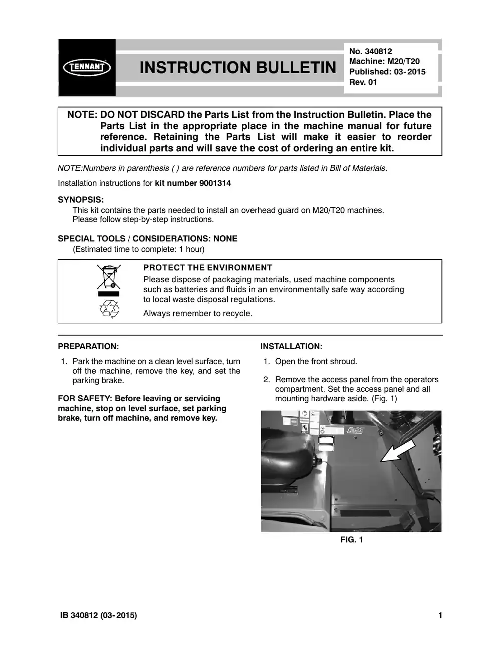
Tennant M20 instruction bulletin 340812, page 1 of 5
Page 1 of 5 SES ref PF-JYLV-BA7H‌‌​⁠‍‍‌​‌​‍‌⁠‌⁠​⁠‌‌⁠‍‍⁠‌​⁠‌‌​​​‌​‍‌​‍‌‍‍‌‍‌⁠​​​​⁠‍‍‌​​‍‍⁠‌‌​
Text of this page
INSTRUCTION NOTE: DO NOT DISCARD the Parts List Parts List in the appropriate pla reference. Retaining the Parts individual parts and will save the NOTE:Numbers in parenthesis ( ) are reference numb Installation instructions for kit number TN4019662 SYNOPSIS: This kit contains the parts needed to install an ove Please follow step-by-step instructions. SPECIAL TOOLS / CONSIDERATIONS: NONE (Estimated time to complete: 1 hour) PROTECT THE ENVIRONM Please dispose of packaging such as batteries and fluids i to local waste disposal regula Always remember to recycle. PREPARATION: 1. Park the machine on a clean level surface, turn off the machine, remove the key, and set the parking brake. FOR SAFETY: Before leaving or servicing machine, stop on level surface, set parking brake, turn off machine, and remove key. IB 340812 (03- 2015) No. 340812 Machine: M20/T20 N BULLETIN Published: 03- 2015 Rev. 01 from the Instruction Bulletin. Place the ace in the machine manual for future s List will make it easier to reorder e cost of ordering an entire kit. bers for parts listed in Bill of Materials. erhead guard on M20/T20 machines. MENT g materials, used machine components in an environmentally safe way according ations. . INSTALLATION: 1. Open the front shroud. 2. Remove the access panel from the operators compartment. Set the access panel and all mounting hardware aside. (Fig. 1) FIG. 1 1
Tennant M20 instruction bulletin 340812, page 2 of 5
Page 2 of 5
Text of this page
3. Remove the plastic plug from the control panel located next to the operators seat. Discard the plastic plug. (Fig. 2) FIG. 2 4. For machines equipped with spray wand option only: Remove the spray wand bracket from the machine. Set the spray wand bracket aside. (Fig. 3) Spray wand bracket FIG. 3 2 5. Use two hex screws (4) and two flat washers (12) to install the left overhead guard tube (2) onto the machine. Reinstall the spray wand bracket over the foot on the left overhead guard tube if the bracket was removed in the previous step. Do not completely tighten the hex screws since it may be necessary to move the left tube when installing the rest of the kit. (Fig. 4 / Fig. 5) 4 11 2 11 4 Install front hex screw first FIG. 4 FIG. 5 IB 340812 (03- 2015)
Tennant M20 instruction bulletin 340812, page 3 of 5
Page 3 of 5
Text of this page
6. Use two hex screws (4) and two flat washers (5) and (12) to install the right overhead guard tube (3) onto the machine. Do not completely tighten the hex screws since it may be necessary to move the right tube when installing the rest of the kit. (Fig. 6 / Fig. 7) 3 4 5 4 11 FIG. 6 FIG. 7 IB 340812 (03- 2015) 3
Tennant M20 instruction bulletin 340812, page 4 of 5
Page 4 of 5
Text of this page
7. Use seven hex screws (4), fourteen flat washers (5), and seven hex nuts (6) to install the overhead guard top onto the left overhead guard tube (2) and right overhead guard tube (3). Do not completely tighten the hex screws since it may be necessary to move the left overhead guard tube when installing the rest of the kit. (Fig. 8) 8. Use a hex nut (10) and flat washer (9) to the install the mirror (8) onto the mirror bracket (7). (Fig. 8) 3 4 5 8 10 7 9 5 6 FIG 4 9. Use a hex screw (4), two flat washers (5), and a hex nut (6) to install the mirror assembly onto the overhead guard assembly. (Fig. 8) 10. Tighten all loose hardware from the previous steps. 11. Reinstall the access panel into the operators compartment. (Fig. 1) 1 4 5 2 5 6 Install mirror (8), mirror mounting bracket (7), and mounting hardware after overhead guard (1) has been installed onto left (2) and right (3) tubes G. 8 IB 340812 (03- 2015)
Tennant M20 instruction bulletin 340812, page 5 of 5
Page 5 of 5
Text of this page
Bill of Materials for OHG Kit Tennant Ref. Part No. Description o TN4019662 OHG Kit, Ci [M20 And T Y 1 TN4032916 Guard Wldt, Top, OHG Y 2 TN1022265 Tube Wldt, Leg, OHG, L Y 3 TN1022266 Tube Wldt, Leg, OHG, R Y 4 TN4043258 Screw, Hex, M10 X 1.5 Y 5 TN4034138 Washer, Flat, 0.38 Std Y 6 TN4016826 Nut, Hex, Lock, M10 X 1 Y 7 TN4033561 Bracket, Mtg, Mirror, Re Y 8 TN369787 Mirror, Flat, 5.1d Y 9 TN4034137 Washer, Flat, 0.31, Std Y 10 TN4042533 Nut, Hex, Std, .31- 18 Y 11 TN4037922 Washer, Flat, 0.40B 1.1 TENNANT P. O. Bo Minneapolis, M IB 340812 (03- 2015) t, CI [M20 and T20]- TN4019662 Qty. T20] 1 1 LH, Pntd 1 RH, Pntd 1 X 30, 8.8 12 17 1.5, Nl 8 earview 1 1 1 1 12D .12,SS 3 COMPANY ox 1452 MN 55440-1452 5

Switch Kit, Press, Replmt [S30]

Tennant instruction bulletin 9009246 rev. 00Published 06-2015Kit 9009247

What it’s for: Replace the pressure switch on M20, M30, S20, S30, 355, 385, 6500, 6550, 6600, 6650, 6400, 8200, 8210, 8400, and 8410 machines.

  • Machines: M20, M30, S20, S30
  • M20: all
  • Power: gasoline, LPG and diesel
  • Applies to: lights

Time: 30 minutes · Special tools: NONE

Safety warnings (from the bulletin, word for word)

  • FOR SAFETY: Before leaving or servicing machine, stop on level surface, turn off machine, and remove key.
  • WARNING: Always disconnect battery cables from machine before working on electrical components.

Parts

Parts for Tennant instruction bulletin 9009246
ItemPart numberQtyDescriptionPrice
TN4010414Old # 90092471Switch Kit, Press, Replmt [S30]KitCall for availability 800-440-6723
1TN4037765Old # 10528851Switch, Press, Adj [4- 16 In Wtr]$72.10/EA

Bulletin PDF: Sign in to view or downloadSign in to download

Installation instructions (5 pages)
Tennant M20 instruction bulletin 9009246, page 1 of 5
Page 1 of 5 SES ref PF-5MMP-52VU‌‌​⁠‍‍‌​‌​‍‌⁠‌⁠​⁠‌‌⁠​‍‌‍‌⁠‍​​​​‌​‍‌​​⁠⁠​​⁠⁠‍​⁠​‍‍‌⁠‌‍⁠‍‍⁠​⁠‌
Text of this page
INSTRUCTION NOTE: DO NOT DISCARD the Parts List Parts List in the appropriate pla reference. Retaining the Parts individual parts and will save the NOTE: Numbers in parenthesis ( ) are reference num Installation instructions for kit number TN4010414 SYNOPSIS: This kit contains the parts needed to replace the p 6500, 6550, 6600, 6650, 6400, 8200, 8210, 8400, Please follow step-by-step instructions. SPECIAL TOOLS / CONSIDERATIONS: NONE (Estimated time to complete: 30 minutes) PROTECT THE ENVIRON Please dispose of packagin and hazardous fluids in an to local waste disposal regu Always remember to recyc PREPARATION: 1. Park the machine on a clean level surface, turn off the machine, remove the key, and set the parking brake. FOR SAFETY: Before leaving or servicing machine, stop on level surface, turn off machine, and remove key. 2. Disconnect the battery cables from the battery. WARNING: Always disconnect battery cables from machine before working on electrical components. 3. Open covers / shrouds / panels necessary to access the pressure switch. IB 9009246 (06- 2015) No. 9009246 Machine: See Below N BULLETIN Published: 06- 2015 Rev. 00 from the Instruction Bulletin. Place the ace in the machine manual for future s List will make it easier to reorder e cost of ordering an entire kit. mbers for parts listed in Bill of Materials. pressure switch on M20, M30, S20, S30, 355, 385, , and 8410 machines. NMENT ng materials, old machine components, environmentally safe manner according ulations. cle. 1
Tennant M20 instruction bulletin 9009246, page 2 of 5
Page 2 of 5
Text of this page
INSTALLATION: NOTE: Refer to Fig.4 / Fig. 5 for the S30 pressure switch location, Fig. 6 for S20 pressure switch location, and Fig. 7 for the M20 / M30 pressure switch location. Refer to the Parts Manuals for pressure switch locations on out of production machines. 1. Remove parts / components necessary to access the pressure switch. Set all removed components and hardware aside. 2. Disconnect the main wire harness from the pressure switch. 3. Disconnect the vacuum hoses from the pressure switch. Note / mark where hoses were connected before disconnecting the hoses from the pressure switch. 4. Remove the pressure switch from the machine. Set all mounting hardware aside. Discard the pressure switch. 5. Loosen the screw securing the cover to the new pressure switch (1) and remove the cover from the new pressure switch. Set the cover / screw aside. (Fig. 1) FIG. 1 2 6. Set the pressure switch to the appropriate setting for the machine. Refer to instructions included with the pressure switch for additional information. (Fig. 2 / Fig. 3) Machine Model Setting S20 10 inch H2O S30 15 inch H2O M20 8 inch H2O M30 8 inch H2O 6400E 6.5 inch H2O 355E 8 inch H2O 6550E 8 inch H2O 6400 8 inch H2O 8200 8 inch H2O 8210 8 inch H2O 355 11 inch H2O 385 11 inch H2O 6550 11 inch H2O 6600 11 inch H2O 6650 11 inch H2O 8400 11 inch H2O 8410 11 inch H2O 6500 11 inch H2O FIG. 2 FIG. 3 IB 9009246 (06- 2015)
Tennant M20 instruction bulletin 9009246, page 3 of 5
Page 3 of 5
Text of this page
7. Reinstall the cover onto the pressure switch (1). 8. Use saved hardware to install the new pressure switch (1) onto the machine. 9. Connect the vacuum hoses to the pressure switch. 10. Connect the main wire harness to the pressure switch (1). 11. Reinstall all components removed to install the pressure switch (1). S30 - Pressure Switch Location (SN 006501 - ) Filter cover FRONT FIG IB 9009246 (06- 2015) 12. Start and test machine. Observe pressure switch hose connections for leaks. Close the hopper door, turn on the vacuum fan, and set the machine to the highest cleaning / sweeping speed. The clogged filter light should illuminate or there should be a clogged filter alert on the LCD. If there is no clogged filter alert, inspect the hoses / connections to the pressure switch for leaks. Set M4 pan screws (Qty. 2) aside Disconnect both vacuum hoses from pressure switch Pressure switch plate Replace existing pressure switch with new pressure switch (1) Upper pre- filter box G. 4 3
Tennant M20 instruction bulletin 9009246, page 4 of 5
Page 4 of 5
Text of this page
S30 - Pressure Switch Location (SN 000000 - 006500) D Filter housing FIG S20 - Pressure Switch Location Set M4 hex nuts (Qty. 2) aside FIG 4 Set M4 pan screws (Qty. 2) and M4 hex nuts (Qty. 2) aside Set M8 hex screws (Qty. 3) and flat washers (Qty. 3) aside Disconnect both vacuum hoses from pressure switch Replace existing Cover pressure switch plate with new pressure g switch (1) G. 5 Set M4 pan screws (Qty. 2) aside Replace existing pressure switch with new pressure switch (1) Disconnect both vacuum hoses from pressure switch Hopper back plate G. 6 IB 9009246 (06- 2015)
Tennant M20 instruction bulletin 9009246, page 5 of 5
Page 5 of 5
Text of this page
M20 / M30 - Pressure Switch Location Hopper lift weldment Set M4 pan screws (Qty. 2) and lock washers (Qty. 2) aside Disconnect both vacuum hoses from Replace existing Hopper cover pressure switch pressure switch with new pressure switch (1) FIG. 7 Bill Of Materials For Switch Kit, Press, Replmt [S30]- TN4010414 Tennant Ref. Part No. Description Qty. o TN4010414 ) Switch Kit, Press, Replmt [S30] 1 Y 1 TN4037765 Switch, Press, Adj [4- 16 In Wtr] 1 TENNANT COMPANY P. O. Box 1452 Minneapolis, MN 55440-1452 IB 9009246 (06- 2015) 5

Control Box Assy Kit, Replmt, Telem [USA]

Tennant instruction bulletin 9010087 rev. 01Published 09-2015Kit 9010085

What it’s for: Replace telemetry module on 5680, 5700, 6100E, 6200E, M20, T20, M30, 8300, S20E, S20, S30, SS5, T5, T5E, T7, SSR, T12, T16, and T17 machines.

  • Machines: M20, M30, S20, S30, T12, T16, T17, T20
  • M20: all
  • Power: gasoline, LPG and diesel
  • Applies to: telemetry

Time: 45 minutes · Special tools: NONE

Safety warnings (from the bulletin, word for word)

  • FOR SAFETY: Before leaving or servicing machine, stop on level surface, turn off machine, remove key, and set parking brake (if equipped).
  • WARNING: Always disconnect battery cables from machine before working on electrical components. 1

Parts

Parts for Tennant instruction bulletin 9010087
ItemPart numberQtyDescriptionPrice
TN4011098Old # 90100851Control Box Assy Kit, Replmt, Telem [USA]Kit$1,623.00/EA
1TN4184642Old # 10694671Control Box Assy, Telem [USA]Call for availability 800-440-6723

Bulletin PDF: Sign in to view or downloadSign in to download

Installation instructions (3 pages)
Tennant M20 instruction bulletin 9010087, page 1 of 3
Page 1 of 3 SES ref PF-DW3X-JJMW‌‌​⁠‍‍‌​‌​‍‌⁠‌⁠​⁠‌‌⁠⁠‍‍⁠‍⁠‌‍​​​‌​‍‌​‌‌​‌‍‌‌​​‍​‍⁠​⁠‌​‍‌‌‌​​‍
Text of this page
INSTRUCTION B NOTE: DO NOT DISCARD the Parts List Parts List in the appropriate pla reference. Retaining the Parts individual parts and will save the NOTE: Numbers in parenthesis ( ) are reference num Installation instructions for kit number TN4011098 SYNOPSIS: This kit contains the parts needed to replace telem T20, M30, 8300, S20E, S20, S30, SS5, T5, T5E, Please follow step-by-step instructions. SPECIAL TOOLS / CONSIDERATIONS: NONE (Estimated time to complete: 45 minutes) The IRIS (telemetry module) must be activated to function until it is activated. Call for assistance (N CCC) activating the module after all telemetry com serial number and IRIS module SIM number (loca when calling for activation. PROTECT THE ENVIRONM Please dispose of packaging such as batteries and fluids i to local waste disposal regula Always remember to recycle. TROUBLESHOOTING: 1. Prior to replacing the telemetry control box, call Technical Support / CCC to troubleshoot the telemetry control box and confirm it needs to be replaced. 2. Proceed with the instructions in this IB to replace the telemetry module if troubleshooting indicates there is a problem with the telemetry module. IB 9010087 (09- 2015) No. 9010087 Machine: See Below BULLETIN Published: 09- 2015 Rev. 01 from the Instruction Bulletin. Place the ace in the machine manual for future s List will make it easier to reorder e cost of ordering an entire kit. mbers for parts listed in Bill of Materials. metry module on 5680, 5700, 6100E, 6200E, M20, T7, SSR, T12, T16, and T17 machines. complete this installation. The module will not North America - Technical Support / Australia - mponents have been installed. Have machine ated on back of IRIS control box assembly) ready MENT g materials, used machine components in an environmentally safe way according ations. . PREPARATION: 1. Park the machine on a clean level surface, turn off the machine, remove the key, and set the parking brake (if equipped). FOR SAFETY: Before leaving or servicing machine, stop on level surface, turn off machine, remove key, and set parking brake (if equipped). 2. Gas / LP / Diesel Machines: Disconnect the battery cables from the battery. Battery Machines: Disconnect the battery cable from the machine. WARNING: Always disconnect battery cables from machine before working on electrical components. 1
Tennant M20 instruction bulletin 9010087, page 2 of 3
Page 2 of 3
Text of this page
INSTALLATION: 1. Disconnect the telemetry harness and antenna cable from the existing telemetry module. (Fig. 1) FIG. 1 2. Remove the telemetry module from the machine. Set the hardware and telemetry module aside. Refer to applicable installation Instruction Bulletins (IB) and Parts Manuals for telemetry module locations. NOTE: Do not discard the removed telemetry module until after the new telemetry module (1) is installed on the machine and fully operational. 3. Remove the additional SIM label from the back of the control box (1) and set label aside in a safe place. The number on the SIM label will be needed for activating the machine. (Fig. 2) FIG. 2 2 4. Use saved hardware to install the new telemetry module (1) onto the machine. 5. Connect the telemetry harness and antenna cable to the telemetry module (1). (Fig. 1) 6. Reconnect the battery cables to the battery / reconnect the battery cable to the machine. 7. Gas / LP / Diesel Machines: Turn the key to the ON position, but do not start the machine. Battery Machines: Turn the key to the ON position. 8. Complete the repair order. Select Failed to Report - Faulty Module from the Symptom Search pull down menu. Include the machine model number and serial number. (Fig. 3) FIG. 3 9. Follow standard return process to return malfunctioning telemetry unit to Tennant Company. 10. North America Customer Locations: Activate the IRIS (telemetry module): Call Technical Support (between hours of 7:00 am and 5:00 pm CST) for assistance to activate the module. The IRIS telemetry system must be activated to complete this install. Have the machine serial number and IRIS module SIM number ready when calling for activation. IB 9010087 (09- 2015)
Tennant M20 instruction bulletin 9010087, page 3 of 3
Page 3 of 3
Text of this page
11. Australia Customer Locations: Activate the IRIS (telemetry module): Call CCC (between hours of 8:00 am and 5:00 pm AEST) and ask to be routed to the IRIS expert for assistance to activate the module. The IRIS telemetry system must be activated to complete this install. Have the machine serial number and IRIS module SIM number ready when calling for activation. NOTE: The IRIS (telemetry module) must be activated to complete this installation. The module will not function until it is activated. Call for assistance activating the module after all telemetry components have been installed. Bill of Materials for Control Box Assy Tennant Ref. Part No. Description 1 TN4184642 Control Box Assy, Telem TENNANT P. O. Bo Minneapolis, M IB 9010087 (09- 2015) y Kit, Replmt, Telem [USA] - TN4011098 Qty. [USA] 1 COMPANY ox 1452 MN 55440-1452 3

Replace the steering column on M20 / T20 / M30 / S30 machines.

Tennant instruction bulletin 328288 rev. 00Published 05-2011Kit 322305

What it’s for: Replace the steering column on M20 / T20 / M30 / S30 machines.

  • Machines: M20, M30, S30, T20
  • M20: all
  • Power: gasoline, LPG and diesel

Time: S30 -- 1 hour (Pages 1--8 · Special tools: NONE

Safety warnings (from the bulletin, word for word)

  • WARNING: Lift arm pinch point. Stay clear of hopper lift arms.
  • WARNING: Raised hopper may fall. Engage hopper support bar.
  • FOR SAFETY: Before leaving or servicing machine, stop on level surface, turn off machine, remove key, and set parking brake.

Parts

Parts for Tennant instruction bulletin 328288
ItemPart numberQtyDescriptionPrice
TN4033762Old # 3223051KitKitCall for availability 800-440-6723

Bulletin PDF: Sign in to view or downloadSign in to download

Installation instructions (12 pages)
Tennant M20 instruction bulletin 328288, page 1 of 12
Page 1 of 12 SES ref PF-LSSA-6KSN‌‌​⁠‍‍‌​‌​‍‌⁠‌⁠​⁠‌‌⁠‍‍‌⁠⁠⁠‍⁠​​​‌​‍‌​‍⁠⁠​⁠​‍‌‍⁠‌‌‌‌​​​⁠⁠‌‍​‌​
Text of this page
INSTRUCTION NOTE: DO NOT DISCARD the Parts List Parts List in the appropriate pla reference. Retaining the Parts individual parts and will save the NOTE: Numbers in parenthesis ( ) are reference num Installation instructions for kit number TN4033762 SYNOPSIS: This kit contains the parts needed to replace the s Please follow step-by-step instructions. SPECIAL TOOLS / CONSIDERATIONS: NONE (Estimated time to complete: S30 -- 1 hour (Pages PROTECT THE ENVIRON Please dispose of packagin and hazardous fluids in an to local waste disposal regu Always remember to recyc PREPARATION (S30): 1. Park the machine on a clean level surface. 2. Completely raise the hopper and engage the hopper support bar. WARNING: Lift arm pinch point. Stay clear of hopper lift arms. WARNING: Raised hopper may fall. Engage hopper support bar. 3. Turn off the engine, remove the key, and set the parking brake. FOR SAFETY: Before leaving or servicing machine, stop on level surface, turn off machine, remove key, and set parking brake. 4. Use the steering tilt to lower the steering wheel to the lowest position. IB 328288 (05--2011) No. 328288 Machine: M20/T20/M30/ N BULLETIN S30 Published: 05--2011 Rev. 00 from the Instruction Bulletin. Place the ace in the machine manual for future s List will make it easier to reorder e cost of ordering an entire kit. mbers for parts listed in Bill of Materials. steering column on M20 / T20 / M30 / S30 machines. s 1--8), M20 / T20 / M30 -- 45 minutes (Pages 9--12) NMENT ng materials, old machine components, environmentally safe manner according ulations. cle. INSTALLATION (S30): 1. Remove the plastic rivets holding the rubber shroud to the front of the machine. Set the rivets aside. Refer to FIg. 1. FIG. 1 1
Tennant M20 instruction bulletin 328288, page 2 of 12
Page 2 of 12
Text of this page
2. Pull the rubber skirt aside to expose the steering mechanism. Refer to Fig. 2. FIG. 2 3. Cut the cable tie securing the wire harness and hydraulic hoses together. Refer to FIg. 3. FIG. 3 4. Disconnect the main wire harness from the steering assembly. 5. Remove the horn button from the steering wheel and disconnect the wire from the horn button. Set the horn assembly aside. Refer to FIg. 4. FIG. 4 2 6. Remove the M20 jam nut from the steering assembly. Set the M20 jam nut aside. Refer to Fig. 5. FIG. 5 7. Remove the steering wheel from the steering column. Set the steering wheel aside. 8. Remove the rubber boot from the steering column. Set the rubber boot aside. Refer to Fig. 6. FIG. 6 IB 328288 (05--2011)
Tennant M20 instruction bulletin 328288, page 3 of 12
Page 3 of 12
Text of this page
9. Remove the t--knob from the steering tilt assembly. It may be necessary to use towels to avoid marring the surfaces of the knob and the steering lock pin when removing the t--knob. Set the t--knob aside. Refer to Fig. 7. FIG. 7 10. Remove the two M6 SEMS hex screws securing the steering tilt assembly to the machine. Set the M6 SEMS hex screws aside. Refer to Fig. 8. FIG. 8 IB 328288 (05--2011) 11.Remove the steering tilt assembly from the machine. Set the steering tilt assembly aside. Refer to Fig. 9 and Fig. 10. FIG. 9 FIG. 10 12. Remove the four M6 SEMS hex screws securing the steering assembly to the machine. Set the M6 SEMS hex screws aside. Refer to Fig. 11. FIG. 11 3
Tennant M20 instruction bulletin 328288, page 4 of 12
Page 4 of 12
Text of this page
13. Remove the steering assembly from the machine. Refer to Fig. 12. FIG. 12 14. Remove the steering column from the hydraulic steering control. Set the four M10 hex screws aside. Refer to Fig. 13. FIG. 13 4 15. Remove the flange bearings from the tilt steering bracket. Set the flange bearings aside. Refer to Fig. 14. Flange bearings Collars Tilt steering bracket Steering column FIG. 14 16. Remove the tilt steering bracket from the steering column. Set the tilt steering bracket, collars, and hardware aside. Refer to Fig. 14. IB 328288 (05--2011)
Tennant M20 instruction bulletin 328288, page 5 of 12
Page 5 of 12
Text of this page
17. Install the tilt steering bracket onto the new steering column (1). Be sure the tilt steering bracket is aligned on the steering column as shown in Fig. 16 and the white plastic horn contact is touching the lower collar on the tilt steering bracket. Torque the socket screws to 27--35 Ft. Lbs. (37--48 Nm). FIG. 15 18. Apply Blue Loctite onto the threads of the four M10 hex screws. 19. Use the four M10 hex screws to install the steering column onto the hydraulic steering control. Torque the M10 hex screws to 27--35 Ft. Lbs. (37--48 Nm). Refer to Fig. 16. FIG. 16 Loctite is a trademark of the Henkel Corporation, USA IB 328288 (05--2011) 20. Install the flange bearings onto the tilt steering bracket. Refer to Fig. 17. FIG. 17 21. Insert the steering column assembly into the machine. Refer to Fig. 18. FIG. 18 22. Use two M6 SEMS hex screws to secure the steering assembly to the machine. Torque the M6 SEMS hex nuts to 5.6--7.3 Ft. Lbs. (7.6--9.9 Nm). Refer to Fig. 19. FIG. 19 5
Tennant M20 instruction bulletin 328288, page 6 of 12
Page 6 of 12
Text of this page
23. Use a 2 X 4 board to elevate the steering column assembly up into the machine. Refer to Fig. 20. FIG. 20 24. Install two M6 SEMS hex screws to secure the other side of the steering column assembly in the machine. Torque the M6 SEMS hex nuts to 5.6--7.3 Ft. Lbs. (7.6--9.9 Nm). Refer to Fig. 21. FIG. 21 25. Install the steering tilt assembly into the machine. Position the tilt steering locking pin in the top hole in the tilt steering bracket. Refer to Fig. 22. FIG. 22 6 26. Apply Blue Loctite onto the treads of the tilt steering locking pin and install the t--knob onto the steering tilt assembly. Refer to Fig. 23. FIG. 23 27. Hold the t--knob so the tilt steering locking pin is centered in the hole and does not touch any of the the edges and install two M6 SEMS hex screws to secure the steering tilt assembly to the machine. Refer to Fig. 24. FIG. 24 28. Install the rubber boot onto the steering column. Refer to Fig. 25. FIG. 25 29. Apply Blue Loctite onto the threads of the M20 jam nut. IB 328288 (05--2011)
Tennant M20 instruction bulletin 328288, page 7 of 12
Page 7 of 12
Text of this page
30. Install the steering wheel onto the steering column and use the M20 jam nut to secure the steering wheel onto the column. Torque the M20 jam nut to 10--13 Ft. Lbs. (13--18 Nm). Refer to Fig. 26. FIG. 26 31. Reassemble the horn button, reconnect the wire to the horn button, and insert the horn button into the steering wheel. Refer to Fig. 27. FIG. 27 32. Connect the horn lead on the main wire harness to the steering assembly. Refer to Fig. 28 and Fig. 29. FIG. 28 IB 328288 (05--2011) FIG. 29 33. Neatly bundle the main wire harness to the hydraulic hoses and use a wire tie to secure the bundle together. Refer to Fig. 30. FIG. 30 34. Pull the steering tilt knob and move the steering wheel through the various positions to ensure the steering tilt assembly is functioning properly. 35. Reinstall the rubber skirt to the frame of the machine. Use extra rivets included in the kit to replace rivets that may have been broken. 36. Disengage the hopper support bar. 37. Start the machine and lower the hopper. Press the horn button to ensure the horn functions. 7
Tennant M20 instruction bulletin 328288, page 8 of 12
Page 8 of 12
Text of this page
FIG 8 24 G. 31 IB 328288 (05--2011)
Tennant M20 instruction bulletin 328288, page 9 of 12
Page 9 of 12
Text of this page
PREPARATION (M20, M30, T20): 1. Park the machine on a clean level surface. 2. Turn off the engine, remove the key, and set the parking brake. FOR SAFETY: Before leaving or servicing machine, stop on level surface, turn off machine, remove key, and set parking brake. 3. Use the steering tilt to lower the steering wheel to the lowest position. 4. Open the front shroud. INSTALLATION (M20, M30, T20): Refer to Fig. 46 for Illustration. 1. Remove the horn button from the steering wheel and disconnect the wire from the horn button. Set the horn assembly aside. Refer to Fig. 32. FIG. 32 2. Remove the M20 jam nut from the steering assembly. Set the M20 jam nut aside. Refer to Fig. 33. FIG. 33 IB 328288 (05--2011) 3. Remove the steering wheel from the steering column. Set the steering wheel aside. 4. Remove the rubber boot from the steering column. Set the rubber boot aside. Refer to Fig. 34. FIG. 34 5. Use the steering tilt wheel to raise the steering wheel to the highest position 6. Disconnect the horn wire from the machine harness. Refer to Fig. 35. FIG. 35 7. Remove the four socket bolts from the two collars on the tilt steering bracket. Refer to Fig. 36. FIG. 36 9
Tennant M20 instruction bulletin 328288, page 10 of 12
Page 10 of 12
Text of this page
8. Slide the old column down through the steering bellows. 9. Remove the four bolts mounting the column to the hydraulic steering valve and discard the old steering column. Refer to Fig. 37. FIG. 37 10. Apply Blue Loctite onto the threads of the four M10 hex screws. 11. Fasten the new steering column onto the steering valve with the horn wire facing the battery. Torque the M10 hex screws to 27--35 Ft. Lbs. (37--48 Nm). Refer to Fig. 38. FIG. 38 12. Remove the steering column boot from the top of the new steering column, then slide the assembly up through the steering bellows. 10 13. Loosely fasten the two collars over the new steering column. Refer to Fig. 39. FIG. 39 14. Position the steering column so that the top of the white collar (where the horn wire mounts) presses up against the lower collar. Then tighten the four socket bolts on the two collars to secure in position. Torque the socket screws to 27--35 Ft. Lbs. (37--48 Nm). Refer to Fig. 40. FIG. 40 IB 328288 (05--2011)
Tennant M20 instruction bulletin 328288, page 11 of 12
Page 11 of 12
Text of this page
15. Tilt the steering wheel into all the positions and check for clearance. Ensure that when the steering wheel is in the lowest position that the hoses do not contact the switch. If it does, loosen the two collars and reposition. Refer to Fig. 41. FIG. 41 16. Ensure that when the steering wheel is in the highest position that the hoses do not contact the battery. If it does, loosen the two collars and reposition. Refer to Fig. 42. FIG. 42 17. Fasten the rubber boot onto the top of the steering column. . Refer to Fig. 43. FIG. 43 IB 328288 (05--2011) 18. Mount the steering wheel and tighten with the M20 jam nut using Blue Loctite. Torque the M20 jam nut to 10--13 Ft. Lbs. (13--18 Nm). Refer to Fig. 44. FIG. 44 19. Connect the (lower) horn wire harness to the machine harness. Refer to Fig. 45. FIG. 45 20. Connect the horn assembly to the top steering column wire, then snap the horn assembly into the steering wheel. Refer to Fig. 46. FIG. 46 21. Check the horn and steering for proper operation. 11
Tennant M20 instruction bulletin 328288, page 12 of 12
Page 12 of 12
Text of this page
6 FIG 12 G. 47 IB 328288 (05--2011)

Panel Kit, Pod, Afmkt [Std, M20/M30]

Tennant instruction bulletin 9015638 rev. 03Published 06-2021Kit 9015041, 9015634, 9015635

What it’s for: Replace standard pod assembly on M20/M30/T20/M17 machines.

  • Machines: M17, M20, M30, T20
  • M20: all
  • Power: gasoline, LPG and diesel

Time: 45- 90 minutes · Special tools: NONE

Safety warnings (from the bulletin, word for word)

  • FOR SAFETY: Before leaving or servicing machine, stop on level surface, turn off machine, set parking brake, and remove key.
  • WARNING: Always disconnect battery cables from machine before working on electrical components.
  • FOR SAFETY: Before leaving or servicing machine, stop on level surface, turn off machine, and remove key.

Parts

Parts for Tennant instruction bulletin 9015638
ItemPart numberQtyDescriptionPrice
TN4022936Old # 90150411Panel Kit, Pod, Afmkt [M17,Standard LCD]KitCall for availability 800-440-6723
TN4023704Old # 90156341Panel Kit, Pod, Afmkt [Std, M20/M30]Kit$1,198.60/EA
TN4023705Old # 90156351M30] 1 Bill Of Materials For Panel Kit, Pod, Afmkt [Std, T20]KitCall for availability 800-440-6723
1TN4037516Old # 12230061Panel Assy, Console [Std M20/M30]Call for availability 800-440-6723
1TN4226512Old # 12230071Panel Assy, Console [Std T20]Call for availability 800-440-6723
1TN1219319Old # 12193191Panel Assy [M17, UL, Standard LCD]Call for availability 800-440-6723

Bulletin PDF: Sign in to view or downloadSign in to download

Installation instructions (13 pages)
Tennant M20 instruction bulletin 9015638, page 1 of 13
Page 1 of 13 SES ref PF-GJCL-IVZB‌‌​⁠‍‍‌​‌​‍‌⁠‌⁠​⁠‌‌⁠‍‍​⁠‌‍⁠​​​​‌​‍‌​⁠‌⁠​‌‍​‍⁠​‍​​‌⁠⁠‍‌‌⁠‌‍‍⁠
Text of this page
INSTRUCTION B NOTE: DO NOT DISCARD the Parts List Parts List in the appropriate pla reference. Retaining the Parts individual parts and will save the NOTE: Numbers in parenthesis ( ) are reference num Installation instructions for kit number TN4023704/9015 SYNOPSIS: This kit contains the parts needed to replace stan Please follow step-by-step instructions. SPECIAL TOOLS / CONSIDERATIONS: NONE (Estimated time to complete: 45- 90 minutes) PROTECT THE ENVIRONM Please dispose of packaging such as batteries and fluids i to local waste disposal regula Always remember to recycle. PREPARATION (M20/M30/T20 Only): 1. If steering pod assembly on machine is operable, connect service computer to the pod, turn the key to the ON position, but do not start the machine, start the Capture application, and note machine settings. The new steering pod assembly (1) will need to be configured to the same settings. FOR SAFETY: Before leaving or servicing machine, stop on level surface, turn off machine, set parking brake, and remove key. 2. Disconnect the battery cables from the machine. WARNING: Always disconnect battery cables from machine before working on electrical components. 3. Open the front shroud to access the steering mechanism components. IB 9015638 (06- 2021) No. 9015638 Machine: M20/T20/ BULLETIN M30/M17 Published: 06- 2021 Rev. 03 from the Instruction Bulletin. Place the ace in the machine manual for future s List will make it easier to reorder e cost of ordering an entire kit. mbers for parts listed in Bill of Materials. 5635/TN4022936 ndard pod assembly on M20/M30/T20/M17 machines. MENT g materials, used machine components in an environmentally safe way according ations. . INSTALLATION (M20/M30/T20 Only): 1. Disconnect the steering pod cables from the main wire harness. (Fig. 1) FIG. 1 1
Tennant M20 instruction bulletin 9015638, page 2 of 13
Page 2 of 13
Text of this page
2. Loosen the socket screws (Qty. 2) securing the steering pod assembly into the steering tilt bracket. (Fig. 2/Fig. 3) FIG. 2 3. Pull the steering pod assembly out from the steering assembly. (Fig. 3) 1 Thrust washers (Qty. 2) FRONT FIG 2 4. Remove the two thrust washers from the steering pod assembly. Set the thrust washers aside. Discard the removed steering pod assembly. (Fig. 3) 5. Slide the thrust washers onto the new steering pod assembly (1). (Fig. 3) 6. Insert the new steering pod assembly (1) into the steering assembly. (Fig. 3) 7. Orient the steering pod assembly (1) so the display is positioned correctly in the steering wheel and tighten the two socket screws to secure the steering pod assembly into the steering tilt bracket. (Fig. 2/Fig. 3) 8. Connect the steering pod assembly (1) to the main wire harness. 9. Reconnect the battery cables to the machine. Steering wheel Steering tilt bracket G. 3 IB 9015638 (06- 2021)
Tennant M20 instruction bulletin 9015638, page 3 of 13
Page 3 of 13
Text of this page
PREPARATION (M17 ONLY): 1. If the pod assembly on machine is operable, connect service computer to the pod, turn the key to the ON position, start the Capture application, and note machine settings. The new pod assembly (1) must be configured to the same settings. NOTE: If pod assembly is completely inoperable, the machine configuration settings will need to be set to the optional equipment on the machine and /or set to the standard default settings. Contact TAC (Technical Assistance Center) for further assistance/additional information. 2. If pod assembly on machine is operable, record the hours from the hour meter. FOR SAFETY: Before leaving or servicing machine, stop on level surface, turn off machine, and remove key. 3. Disconnect the battery cable from the machine. WARNING: Always disconnect battery cables from machine before working on electrical components. 4. Remove the access panel from the machine. Set the access panel and all hardware aside. INSTALLATION (M17 ONLY): 1. Disconnect the main wire harness from the pod assembly. (Fig. 4) FIG. 4 IB 9015638 (06- 2021) 2. Loosen the socket set screws in the bearing plate securing the pod assembly to the steering column assembly. (Fig. 5/Fig. 6) FIG. 5 3. Pull the pod assembly out from the steering wheel/steering column assembly. (Fig. 6) 4. Remove the thrust washers from the removed pod assembly and slide the thrust washers onto the new pod assembly (1). Discard the removed pod assembly. (Fig. 6) 5. Insert the new pod assembly (1) into the steering assembly. (Fig. 6) 6. Orient the pod assembly (1) so the display is positioned correctly in the steering wheel and tighten the socket screws to secure the pod assembly into the bearing plate. (Fig. 5/Fig. 6) 7. Connect the pod assembly (1) to the main wire harness. (Fig. 4) 8. Reinstall the access panel onto the machine 9. Reconnect the battery cable to the machine. 3
Tennant M20 instruction bulletin 9015638, page 4 of 13
Page 4 of 13
Text of this page
Note: Steering wheel/steering column assembly/bearing plate do not need to be removed from machine when replacing FRONT standard panel assembly. These items are shown disassembled to better show part locations. Thrust washers (Qty. 2) Steeringwheel Steering column assembly Replace existing Bearing plate steering pod assembly Loosen socket set with new steering pod screws (Qty. 2) assembly (1) FIG. 6 4 IB 9015638 (06- 2021)
Tennant M20 instruction bulletin 9015638, page 5 of 13
Page 5 of 13
Text of this page
TENNANT SERVICE APPLICATION SOFTWARE (ALL MACHINES): The service application software can be accessed or downloaded as described below. For Tennant service personnel equipped with ServiceLink computers, the software is already installed on the service computer. The software application is titled “Service Diagnostics”. (Fig. 7) Icon on Desktop From Start menu From Start menu > All Programs > Tennant Company > Tennant Service Diagnostics FIG. 7 IB 9015638 (06- 2021) For other Service Groups, the Service Application Software can be downloaded from the Tennant Public website as described below. NOTE: If the Service Application Software is currently installed on the service computer, confirm or reinstall the software to ensure latest software version is installed. To access the Service Application Software, go to www.tennantco.com. Depending on geographic location, the website may have a “Log in/Sign Up” button at the upper right or a “My Tennant Customer Sign In” tab at the upper right of the Tennant website. (Fig. 8) Proceed with the software download instructions as described on the following pages. Website with “Log In / Sign Up” button (Access to “My Account”) OR Website with “My Tennant Customer Sign In” tab (Access to My Tennant) FIG. 8 5
Tennant M20 instruction bulletin 9015638, page 6 of 13
Page 6 of 13
Text of this page
Website with “Log In / Sign Up” button: (Access to “My Account”) (ALL MACHINES): 1. Log in or Sign Up to create an account. (Fig. 9) FIG. 9 2. Once logged in to the “My Account” website, click on the “INTERNAL RESOURCES” link. (Fig. 10) FIG. 10 3. Click on the “SERVICE APPLICATION SOFTWARE” link. (Fig. 11) FIG. 11 6 4. Within the Service Application Software page, click on the link titled “Service Diagnostics LE version 1.5.12” or later. (Fig. 12) FIG. 12 5. To download the service software continue to click as instructed then click the Save button. (Fig. 13) FIG. 13 6. Open the “Downloads” folder and locate the “LE_Setup_xxxx” zip file. Open the zip file and double click on the “LE_Setup_xxx” file to install the application software on service computer. Follow instructions on screen to install. (Fig. 14) FIG. 14 7. Proceed to PROGRAM THE CONTROL BOARD. IB 9015638 (06- 2021)
Tennant M20 instruction bulletin 9015638, page 7 of 13
Page 7 of 13
Text of this page
PROGRAM THE CONTROL BOARD (ALL MACHINES): If any problems are encountered during the programming process, contact the Technical Service Department for support. 1. Access the software through either the desktop icon or the Start Menu. The software application is titled “Service Diagnostics”. (Fig. 15/Fig. 16/Fig. 17) FIG. 15 From Start menu FIG. 16 Start menu > All Programs > Tennant Company > Tennant Service Diagnostics FIG. 17 IB 9015638 (06- 2021) 2. Start the Service Software Application program. The following screen will appear. (Fig. 18) FIG. 18 3. Turn the key switch to the ON position. 4. Connect the USB cable to the computer and the USB port on machine. 5. The application software will connect to the machine. (Fig. 19) FIG. 19 If the application remains on the “Connecting to Machine...” screen for an extended period, cycle key or close and restart the application software. If it still fails to connect, restart the computer. 7
Tennant M20 instruction bulletin 9015638, page 8 of 13
Page 8 of 13
Text of this page
6. The following screen appears when the application software is connected to machine (Fig. 20). Enter the machine serial number from the label on machine (ex. M17- 12345678). Select the appropriate model from the drop- down menu. Press the arrow button to advance to next screen. FIG. 20 7. Carefully select the correct installed options on the machine (Fig. 21). This may require visually inspecting the machine to confirm all installed options. Press the arrow button to advance to next screen. NOTE: If the machine is configured with an option it does not have, a fault code may appear during machine start up. FIG. 21 8 8. The application will begin configuring the new control board. Allow the configuration process to be completed. (Fig. 22) FIG. 22 9. The Machine Setup Complete screen appears after configuration is complete. (Fig. 23) FIG. 23 10.Disconnect the USB cable from the machine and turn key off. The machine is now ready for operation. 11.Test machine to ensure all installed options are functioning and no fault codes appear. If a fault code appears, proceed to next step. 12.Reconnect the USB cable to the computer and the machine. The Main Menu will appear on the computer screen. IB 9015638 (06- 2021)
Tennant M20 instruction bulletin 9015638, page 9 of 13
Page 9 of 13
Text of this page
13. Check the machine configuration selections for incorrect installed options. Select the Configuration button. (Fig. 24) FIG. 24 14. Correct the installed options. (Fig. 25) FIG. 25 15. Press the down arrow button to program the machine. A green check appears next to the down arrow button when programmed. (Fig. 25) 16. Cycle key to apply the corrected configuration setting. NOTE: The hour meter on Gas/LPG machines does not need to be reset. The newly installed pod will automatically reset to the correct hour meter reading based on the hour setting (engine run time) from the engine. 17. Disconnect the USB cable from the machine. IB 9015638 (06- 2021) RESET THE HOUR METER (ALL MACHINES): NOTE: Displays included in this section of the IB are from the M17. The same displays exist for the M20/M30/T20 machines but may have slightly different nomenclature. 1. Press and hold the right arrow key and turn the key switch to the ON position. (Fig. 26) FIG. 26 2. The pod assembly (1) should boot to the Service Modes menu. Press the right arrow button/left arrow button to scroll to the CONFIG MODE menu from the Service Modes menu. (Fig. 27) FIG. 27 9
Tennant M20 instruction bulletin 9015638, page 10 of 13
Page 10 of 13
Text of this page
3. Press the main scrub brush pressure button to enter the CONFIG MODE. (Fig. 28) FIG. 28 4. Press either the right arrow button or the left arrow button to scroll to C15: PROPEL H. M. Press the main scrub brush pressure button to enter the C15: Propel H.M. Log in screen. (Fig. 29) FIG. 29 10 5. Log in to C15: Propel H.M. (hour meter reset password is 0000): Press the minus (- ) button to enter 0 (zero) at first asterisk. Press the right arrow button to move to next asterisk and again press the minus (- ) button to enter 0 (zero). Repeat for the remaining asterisks. Press the main scrub brush pressure button when finished. (Fig. 30/Fig. 31) FIG. 30 FIG. 31 IB 9015638 (06- 2021)
Tennant M20 instruction bulletin 9015638, page 11 of 13
Page 11 of 13
Text of this page
6. Reset the hour meter at the C16: Chg Prpl Hr screen: Use the minus (- ) button and plus (+) button to set/reset numbers and the right arrow button to move to the next number. If necessary, use left arrow to move back to previous number. (Fig. 32/Fig. 33) FIG. 32 FIG. 33 NOTE: If hour meter was inaccessible due to pod being inoperable contact TAC (Technical Assistance Center) for the hour meter time from the last time the machine was serviced. 7. Press the main scrub brush pressure button when finished entering the time for the hour meter. IB 9015638 (06- 2021) 8. Press either the right arrow button or the left arrow button to scroll to C17: Scrub H. M. Press the main scrub brush pressure button to enter the C17: Scrub H.M. Log in screen. (Fig. 34) FIG. 34 9. Log in to C17: Scrub H.M. (hour meter reset password is 0000): Press the minus (- ) button to enter 0 (zero) at first asterisk. Press the right arrow button to move to next asterisk and again press the minus (- ) button to enter 0 (zero). Repeat for the remaining asterisks. Press the main scrub brush pressure button when finished. (Fig. 35/Fig. 36) FIG. 35 FIG. 36 11
Tennant M20 instruction bulletin 9015638, page 12 of 13
Page 12 of 13
Text of this page
10.Reset the hour meter at the C18: Chg Scrub Hr screen: Use the minus (- ) button and plus (+) button to set/reset numbers and the right arrow button to move to the next number. If necessary, use left arrow to move back to previous number. (Fig. 37/Fig. 38) FIG. 37 FIG. 38 NOTE: If scrub hour meter was inaccessible due to pod being inoperable contact TAC (Technical Assistance Center) for the hour meter time from the last time the machine was serviced. 11.Press the main scrub brush pressure button when finished entering the time for the hour meter. 12 12.Press either the right arrow button or left arrow button to scroll to Exit Config Mode. Yes should appear under the top line of text. Press the main scrub brush pressure button. (Fig. 39) FIG. 39 13.The Exit Config Mode menu should open. <Yes > should appear under the top line of text. Press the main scrub brush pressure button again to exit the Configuration Mode. (Fig. 40) FIG. 40 14.Turn key switch to OFF position to turn off the machine/exit the Config Mode. 15.M17 Sweeper Scrubbers only: Reset the hopper roll out. See PROGRAMMING/ ADJUSTING THE ROLL OUT ACTUATOR in the M17 Service Manual for detailed instructions how to reset the hopper roll out. IB 9015638 (06- 2021)
Tennant M20 instruction bulletin 9015638, page 13 of 13
Page 13 of 13
Text of this page
Bill Of Materials For Panel Kit, Pod, Afmkt [Std, M20/M30] - TN4023704 Tennant Ref. Part No. Description Qty. 1 TN4037516 ) Panel Assy, Console [Std M20/M30] 1 Bill Of Materials For Panel Kit, Pod, Afmkt [Std, T20] - TN4023705 Tennant Ref. Part No. Description Qty. 1 TN4226512 ) Panel Assy, Console [Std T20] 1 Bill Of Materials For Panel Kit, Pod, Afmkt [M17,Standard LCD] - TN4022936 Tennant Ref. Part No. Description Qty. 1 TN1219319 ) Panel Assy [M17, UL, Standard LCD] 1 TENNANT COMPANY 10400 Clean Street Eden Prairie, MN 55344- 2650 IB 9015638 (06- 2021) 13

Telemetry Kit, LPG, CI [M20 / T20, USA] / Telemetry Kit, Dsl, CI [M20/T20, USA]

Tennant instruction bulletin 9014052 rev. 02Published 12-2015Kit 9014028, 9014029

What it’s for: Install the telemetry system on M20 / T20 machines.

  • Machines: M20, T20
  • M20: all
  • Power: gasoline, LPG and diesel
  • Applies to: telemetry

Time: 1 hour · Special tools: NONE

Safety warnings (from the bulletin, word for word)

  • FOR SAFETY: Before leaving or servicing machine, stop on level surface, turn off machine, and remove key.
  • WARNING: Always disconnect battery cables from machine before working on electrical components.

Parts

Parts for Tennant instruction bulletin 9014052
ItemPart numberQtyDescriptionPrice
TN4197336Old # 90140281Telemetry Kit, LPG, CI [M20 / T20, USA] / Telemetry Kit, Dsl, CI [M20/T20, USA]KitCall for availability 800-440-6723
TN4197337Old # 90140291Telemetry Kit, LPG, CI [M20 / T20, USA] / Telemetry Kit, Dsl, CI [M20/T20, USA]KitCall for availability 800-440-6723
1TN4184642Old # 10694671Control Box Assy, Telem [USA, 3G]Call for availability 800-440-6723
2TN4029531Old # 3609438Screw, Pan, Phl, 10- 14 X 0.75, F/ PlstcCall for availability 800-440-6723
3TN4042243Old # 190658Washer, Flat, 0.19B 0.44D .05, PL, 08$3.20/EA
4TN4030708Old # 10716411Harness, Wire, Gas/LPG [MAKO, Telemetry]$125.34/EA
4TN4030280Old # 10698761Harness, Wire, Dsl [M20 / T20, Telemetry]$133.72/EA
5TN4038889Old # 12108074Wire, Tie [W/.25” Fir Tree Clip]$1.90/EA
6TN4043510Old # 13077313Tie, Cable, Nyl, 11.0L, .14W, 3.0 Max. DCall for availability 800-440-6723
7TN4033472Old # 3157241Antenna, Telem, 18.0 IN [GPRS]Call for availability 800-440-6723
8TN4228167Old # 12175421Guard, ModuleCall for availability 800-440-6723
9TN4030121Old # 10695801Label, Opertnl, Telem [FCC/IC]$4.34/EA

Bulletin PDF: Sign in to view or downloadSign in to download

Installation instructions (12 pages)
Tennant M20 instruction bulletin 9014052, page 1 of 12
Page 1 of 12 SES ref PF-3YGE-MHTT‌‌​⁠‍‍‌​‌​‍‌⁠‌⁠​⁠‌‌⁠⁠⁠‌‍​‍​⁠​​​‌​‍‌​⁠‌‍⁠‌‍‍⁠‍⁠‍‌‌‌‌‍‍‌​‌​‌​​
Text of this page
INSTRUCTION B NOTE: DO NOT DISCARD the Parts List Parts List in the appropriate pla reference. Retaining the Parts individual parts and will save the NOTE: Numbers in parenthesis ( ) are reference num Installation instructions for kit number TN4197336 / 901 SYNOPSIS: This kit contains the parts needed to install the te Please follow step-by-step instructions. SPECIAL TOOLS / CONSIDERATIONS: NONE (Estimated time to complete: 1 hour) The IRIS (telemetry module) must be activated not function until it is activated. Call for assis Australia - CCC) activating the module after a Have machine serial number and IRIS module box assembly) ready when calling for activatio PROTECT THE ENVIRONM Please dispose of packaging such as batteries and fluids i to local waste disposal regula Always remember to recycle. PREPARATION: 1. Start machine. Observe the LCD display for fault / diagnostic codes. All fault / diagnostic codes must be corrected before the IRIS system can be installed onto the machine. FOR SAFETY: Before leaving or servicing machine, stop on level surface, turn off machine, and remove key. 2. Disconnect the battery cables from the battery. WARNING: Always disconnect battery cables from machine before working on electrical components. 3. Open the front shroud. IB 9014052 (12- 2015) No. 9014052 Machine: M20 / T20 BULLETIN Published: 12- 2015 Rev. 02 from the Instruction Bulletin. Place the ace in the machine manual for future s List will make it easier to reorder e cost of ordering an entire kit. mbers for parts listed in Bill of Materials. 14029 elemetry system on M20 / T20 machines. d to complete this installation. The module will stance (North America - Technical Support / all telemetry components have been installed. e SIM number (located on back of IRIS control on. MENT g materials, used machine components in an environmentally safe way according ations. . INSTALLATION: 1. Remove the additional SIM label from the back of the control box (1) and set label aside in a safe place. The number on the SIM label will be needed for activating the machine. (Fig. 1) FIG. 1 1
Tennant M20 instruction bulletin 9014052, page 2 of 12
Page 2 of 12
Text of this page
2. Use the measurements in Fig. 2 to position the telemetry module (1) onto the front shroud and drill a 1/8 in. (3.1750 mm) hole through each existing hole in telemetry module and the inner surface of the front shroud. Do Not drill into the front surface of the front shroud. 1.643 in. (41.74 mm) FIG 2 IB 9014052 (12- 2015) .ni303.7 )mm05.561( G. 2
Tennant M20 instruction bulletin 9014052, page 3 of 12
Page 3 of 12
Text of this page
3. Remove the existing harness from the machine. Discard the removed harness. (Fig. 3) FIG. 3 IB 9014052 (12- 2015) 3
Tennant M20 instruction bulletin 9014052, page 4 of 12
Page 4 of 12
Text of this page
4. Connect the telemetry harness (4) to the engine harness / main wire harness where removed harness was previously installed. (Fig. 4 / Fig. 5) FIG. 4 - G 4 Gas / LP IB 9014052 (12- 2015)
Tennant M20 instruction bulletin 9014052, page 5 of 12
Page 5 of 12
Text of this page
FIG. 5 - IB 9014052 (12- 2015) - Diesel 5
Tennant M20 instruction bulletin 9014052, page 6 of 12
Page 6 of 12
Text of this page
5. Route the telemetry harness (4) along the main wire harness and to the front of the machine. Use several cable ties (6) to secure the telemetry harness to the main wire harness. (Fig. 6) FIG. 6 6. Connect the antenna (7) cable and telemetry harness (4) to the telemetry module (1). (Fig. 7) FIG. 7 7. Use four pan screws (2) and four flat washers (3) to install the telemetry module (1) onto the front shroud. (Fig. 8) FIG. 8 6 IB 9014052 (12- 2015)
Tennant M20 instruction bulletin 9014052, page 7 of 12
Page 7 of 12
Text of this page
8. Drill two 0.25 in. (6.35 mm) holes into the inner surface of the front shroud. Do Not drill into the front surface of the front shroud. (Fig. 9 / Fig. 10) FIG. 9 9. Install two wire tie clips (5) for mounting the antenna (7) to the front shroud. (Fig. 9 / Fig. 10) IB 9014052 (12- 2015) .ni623.6 3 (76.2 FIG 7 )mm96.061( 3.00 in. 20 mm) G. 10
Tennant M20 instruction bulletin 9014052, page 8 of 12
Page 8 of 12
Text of this page
10. Insert a cable tie (6) into each of the wire tie clips (5) above the telemetry module (1). (Fig. 11) FIG. 11 11. Use the cable ties (6) to secure the antenna (7) to the front shroud. (Fig. 12) FIG. 12 12. Drill another 0.25 in. (6.35 mm) hole into the inner surface near the bottom of the front shroud, near the hinge. Do Not drill into the front surface of the front shroud. (Fig. 13) FIG. 13 13. Install another wire tie clip (5) onto the front shroud. (Fig. 13) 8 14. If necessary, bundle the antenna (7) cable and secure the bundled cable with a cable tie (6). (Fig. 14) FIG. 14 15. Arrange the antenna (7) cable next to the telemetry module (1) and secure the telemetry harness (4) and antenna cable into the wire tie clip (5). (Fig. 15) FIG. 15 IB 9014052 (12- 2015)
Tennant M20 instruction bulletin 9014052, page 9 of 12
Page 9 of 12
Text of this page
16. Center the telemetry guard (8) over the telemetry module (1) and align the top edge of the telemetry guard with the top edge of the telemetry module. Drill a 1/8 in. (3.1750 mm) hole through each existing hole in telemetry guard and the inner surface of the front shroud. Do Not drill into the front surface of the front shroud. (Fig. 16) FIG. 16 17. Use four pan screws (2) and four flat washers (3) to install the telemetry module guard (8) over the telemetry module (1) and bundled antenna (7) cable. (Fig. 17) FIG. 17 IB 9014052 (12- 2015) 18. Neatly bundle the telemetry harness (4) and secure bundled cable with a cable tie (6). Use two additional cable ties to secure the engine harness telemetry connector cable to the main wire harness. (Fig. 18) FIG. 18 19. Clean the area in the operator compartment where the telemetry label (9) is to be located and install the telemetry label onto the operator compartment. (Fig. 19) FIG. 19 20. Reconnect the battery cables to the battery 21. Start and test the machine. 22. North America Customer Locations: Activate the IRIS (telemetry module): Call Technical Support (between hours of 7:00 am and 5:00 pm CST) for assistance to activate the module. The IRIS telemetry system must be activated to complete this install. Have machine serial number and IRIS module SIM number ready when calling for activation. 9
Tennant M20 instruction bulletin 9014052, page 10 of 12
Page 10 of 12
Text of this page
23. Australia Customer Locations: Activate the IRIS (telemetry module): Call CCC (between hours of 8:00 am and 5:00 pm AEST) and ask to be routed to the IRIS expert for assistance to activate the module. The IRIS telemetry system must be activated to complete this install. Have machine serial number and IRIS module SIM number ready when calling for activation. NOTE: The IRIS (telemetry module) must be activated to complete this installation. The module will not function until it is activated. Call for assistance activating the module after all telemetry components have been installed. 10 IB 9014052 (12- 2015)
Tennant M20 instruction bulletin 9014052, page 11 of 12
Page 11 of 12
Text of this page
FIG IB 9014052 (12- 2015) G. 20 11
Tennant M20 instruction bulletin 9014052, page 12 of 12
Page 12 of 12
Text of this page
Bill Of Materials For Telemetry Kit, LPG, CI [M20 / T20, USA] - TN4197336 / Telemetry Kit, Dsl, CI [M20/T20, USA] - TN4197337 Tennant Ref. Part No. Description Qty. 1 TN4184642 Control Box Assy, Telem [USA, 3G] 1 2 TN4029531 Screw, Pan, Phl, 10- 14 X 0.75, F/ Plstc 8 3 TN4042243 Washer, Flat, 0.19B 0.44D .05, PL, 08 8 4 TN4030708 Harness, Wire, Gas/LPG [MAKO, Telemetry] 1 4 TN4030280 Harness, Wire, Dsl [M20 / T20, Telemetry] 1 5 TN4038889 Wire, Tie [W/.25” Fir Tree Clip] 4 6 TN4043510 Tie, Cable, Nyl, 11.0L, .14W, 3.0 Max. D 13 7 TN4033472 Antenna, Telem, 18.0 IN [GPRS] 1 8 TN4228167 Guard, Module 1 9 TN4030121 Label, Opertnl, Telem [FCC/IC] 1 TENNANT COMPANY P. O. Box 1452 Minneapolis, MN 55440-1452 12 IB 9014052 (12- 2015)

Caster Kit, Rear Squeegee, AM

Tennant instruction bulletin 9014333 rev. 00Published 09-2016Kit 9014285

What it’s for: Replace a rear squeegee caster wheel assembly on T17 / T20 / M17 / M20 / M30 machines.

  • Machines: M17, M20, M30, T17, T20
  • M20: all
  • Power: gasoline, LPG and diesel

Time: 30 minutes · Special tools: NONE

Safety warnings (from the bulletin, word for word)

  • FOR SAFETY: Before leaving or servicing machine, stop on level surface, turn off machine, set parking brake, and remove key.

Parts

Parts for Tennant instruction bulletin 9014333
ItemPart numberQtyDescriptionPrice
TN4026503Old # 90142851Caster Kit, Rear Squeegee, AMKit$77.10/EA
1TN4036984Old # 12197581Wheel Assy, 03.0d 1.38w 0.500bCall for availability 800-440-6723

Bulletin PDF: Sign in to view or downloadSign in to download

Installation instructions (2 pages)
Tennant M20 instruction bulletin 9014333, page 1 of 2
Page 1 of 2 SES ref PF-K3JD-Z23G‌‌​⁠‍‍‌​‌​‍‌⁠‌⁠​⁠‌‌⁠⁠‌⁠⁠‌‍‍‍​​​‌​‍‌​⁠⁠⁠​​‍‍⁠​‌‌‍‌‌‌‌⁠‍‍‍⁠​⁠‍
Text of this page
INSTRUCTION B NOTE: DO NOT DISCARD the Parts List Parts List in the appropriate pla reference. Retaining the Parts individual parts and will save the NOTE: Numbers in parenthesis ( ) are reference num Installation instructions for kit number TN4026503 SYNOPSIS: This kit contains the parts needed to replace a rea M17 / M20 / M30 machines. Please follow step-by-step instructions. SPECIAL TOOLS / CONSIDERATIONS: NONE (Estimated time to complete: 30 minutes) PROTECT THE ENVIRONM Please dispose of packaging such as batteries and fluids i to local waste disposal regula Always remember to recycle. PREPARATION: 1. Turn on the machine, completely raise the rear squeegee from the floor, turn off the machine, set the parking brake, and remove the key. FOR SAFETY: Before leaving or servicing machine, stop on level surface, turn off machine, set parking brake, and remove key. 2. Disconnect the vacuum hose from the squeegee assembly and remove the squeegee assembly from the machine. Set the squeegee assembly and all mounting hardware aside. IB 9014333 (09- 2016) No. 9014333 Machine: M17 / T17 / BULLETIN M20 / T20 / M30 Published: 09- 2016 Rev. 00 from the Instruction Bulletin. Place the ace in the machine manual for future s List will make it easier to reorder e cost of ordering an entire kit. mbers for parts listed in Bill of Materials. ar squeegee caster wheel assembly on T17 / T20 / MENT g materials, used machine components in an environmentally safe way according ations. . INSTALLATION: 1. Remove the existing rear squeegee wheel assembly from the machine. Discard the existing rear squeegee wheel assembly and hardware. (Fig. 1) 2. Use the hardware provided with the new rear squeegee wheel assembly (1) to install the rear squeegee wheel assembly onto the squeegee caster pivot. Be sure there is no side to side movement of the rear squeegee wheel assembly in the squeegee caster pivot. Also be sure the rear squeegee wheel assembly spins freely in the squeegee caster pivot. (Fig. 1) 3. Connect the grease gun to the rear squeegee wheel assembly (1) zerk and pump the grease gun two times to apply grease into the rear squeegee wheel assembly. (Fig. 1). 4. Reinstall the rear squeegee assembly onto the machine and reconnect the vacuum hose to the rear squeegee assembly. 1
Tennant M20 instruction bulletin 9014333, page 2 of 2
Page 2 of 2
Text of this page
F Do not remove squeegee caster pivot to inst wheel assembly (1). Rear squeegee caster removed to better show pa Replace existing wheel assembl squeegee wheel Squeegee lift cross member FRONT Caster pivot Replace existing rear squeegee wheel assembly with new rear squeegee wheel assembly (1) * M20 / T20 / M30 Machines FIG Bill of Materials for Caster Kit, Tennant Ref. Part No. Description 1 TN4036984 Wheel Assy, 03.0d 1.38w TENNANT P. O. Bo Minneapolis, M 2 M17 / T17 Machines Squeegee frontcoupling FRONT tall rear squeegee r assembly shown art part locations. g rear squeegee ly with new rear l assembly (1) * Do not remove squeegee caster pivot to install rear squeegee wheel assembly (1). Rear squeegee caster assembly shown removed to better show part part locations. * Note: Although only one side of the squeegee assembly is shown, this kit can be used to replace the rear squeegee wheel assembly on either side of the squeegee assembly. G. 1 Rear Squeegee, AM - TN4026503 Qty. w 0.500b 1 COMPANY ox 1452 MN 55440-1452 IB 9014333 (09- 2016)

leaks. Make adjustments as necessary. Bill Of Materials For Pipe Kit, Exhaust, Replmt [Mako Mitsu]

Tennant instruction bulletin 9013160 rev. 00Published 04-2015Kit 9013159

What it’s for: Replace the exhaust pipe on M20 / T20 / M30 machines equipped with Mitsubishi engines.

  • Machines: M10, M20, M30, T20
  • M20: all
  • Power: Gasoline, LPG
  • Engine: Mitsubishi
  • Applies to: Mitsubishi engine

Time: 2 hours · Special tools: NONE

Safety warnings (from the bulletin, word for word)

  • FOR SAFETY: Before leaving or servicing machine, stop on level surface, turn off machine, and remove key.
  • WARNING: Always disconnect battery cables from machine before working on electrical components.
  • FOR SAFETY: When servicing machine, block machine tires before jacking machine up. Use a hoist or jack that will support the weight of the machine. Jack machine up at designated locations only. Support machine with jack stands.

Parts

Parts for Tennant instruction bulletin 9013160
ItemPart numberQtyDescriptionPrice
TN4025234Old # 90131591leaks. Make adjustments as necessary. Bill Of Materials For Pipe Kit, Exhaust, Replmt [Mako Mitsu]Kit$415.30/EA
1TN4030482Old # 10710031Pipe, Exhaust, Flex [Mit 2013]Call for availability 800-440-6723
2TN4036679Old # 10112161Gasket, Exhaust, 2hole, 3.4bc$8.10/EA
3TN9019296Old # 90192961VR, Gasket, Manifold, Exh [Mit]Call for availability 800-440-6723
4TN4041625Old # 081653Nut, Hex, Stover, M8$3.40/EA
5TN4041626Old # 081662Nut, Hex, M10 X 1.50 [Stover]$2.50/EA
6TN4015595Old # 393493Washer, Flat, 0.31, SAE$2.50/EA
7TN4019759Old # 392842Screw, Hex, M10 X 1.5 X 35, 8.8$4.00/EA
8TN4030497Old # 10711131Bracket, Muffler$15.60/EA

Bulletin PDF: Sign in to view or downloadSign in to download

Installation instructions (4 pages)
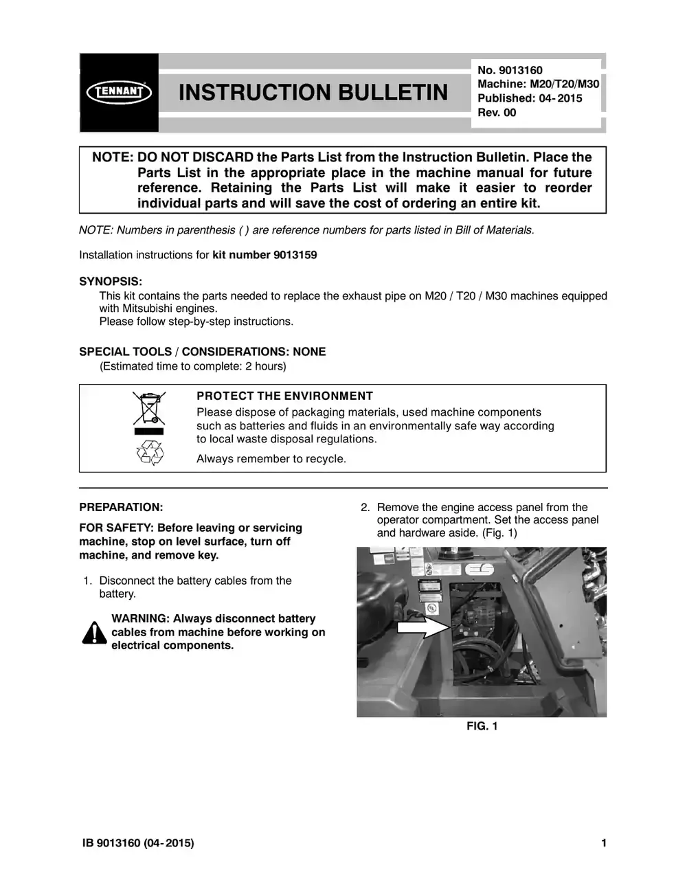
Tennant M20 instruction bulletin 9013160, page 1 of 4
Page 1 of 4 SES ref PF-C3RW-EYDQ‌‌​⁠‍‍‌​‌​‍‌⁠‌⁠​⁠‌‌⁠‍‌‌‍‌​​‍​​​‌​‍‌​⁠‌‌​​⁠​‌‌⁠‌‌‌⁠‍‌​‌‌‍‍​​‌
Text of this page
INSTRUCTION B NOTE: DO NOT DISCARD the Parts List Parts List in the appropriate pla reference. Retaining the Parts individual parts and will save the NOTE: Numbers in parenthesis ( ) are reference num Installation instructions for kit number TN4025234 SYNOPSIS: This kit contains the parts needed to replace the e with Mitsubishi engines. Please follow step-by-step instructions. SPECIAL TOOLS / CONSIDERATIONS: NONE (Estimated time to complete: 2 hours) PROTECT THE ENVIRONM Please dispose of packaging such as batteries and fluids i to local waste disposal regula Always remember to recycle. PREPARATION: FOR SAFETY: Before leaving or servicing machine, stop on level surface, turn off machine, and remove key. 1. Disconnect the battery cables from the battery. WARNING: Always disconnect battery cables from machine before working on electrical components. IB 9013160 (04- 2015) No. 9013160 Machine: M20/T20/M30 BULLETIN Published: 04- 2015 Rev. 00 from the Instruction Bulletin. Place the ace in the machine manual for future s List will make it easier to reorder e cost of ordering an entire kit. mbers for parts listed in Bill of Materials. exhaust pipe on M20 / T20 / M30 machines equipped MENT g materials, used machine components in an environmentally safe way according ations. . 2. Remove the engine access panel from the operator compartment. Set the access panel and hardware aside. (Fig. 1) FIG. 1 1
Tennant M20 instruction bulletin 9013160, page 2 of 4
Page 2 of 4
Text of this page
3. If necessary, jack up the front end of the machine enough to access the exhaust system components. 4. Place a chock behind both rear tires of the machine. 5. Jack up the front end of the machine, place jack stands under the machine, and lower the machine onto the jack stands. Refer to MAINTENANCE section of Operators Manual for instructions how to safely jack up the machine and additional safety information. FOR SAFETY: When servicing machine, block machine tires before jacking machine up. Use a hoist or jack that will support the weight of the machine. Jack machine up at designated locations only. Support machine with jack stands. INSTALLATION: 1. Disconnect the exhaust sensor from the main wire harness. (Fig. 5) 2. Disconnect the existing muffler bracket from the machine. Set the M6 hex screw and flat washer aside. Discard the removed muffler bracket. (Fig. 5) 3. Remove the isolator hanger rod / rubber isolator from the machine. Set the rubber isolator and all mounting hardware aside. Leave the isolator hanger rod installed on the exhaust system and in the rubber isolator. (Fig. 5) 4. Remove the exhaust system from under the machine. 5. Remove any remainder of the old exhaust pipe from the engine. Discard the three M8 hex nuts, three flat washers, and gasket. (Fig. 5) 6. Remove the remainder of the exhaust pipe from the muffler. Discard the exhaust pipe, muffler bracket, gasket, and both M10 hex screws and M10 hex nuts. (Fig. 5) 7. Use two M10 hex screws (5) and two M10 hex nuts (7) to install the new exhaust pipe (1), gasket (2), and muffler bracket (8) onto the muffler. Do not completely tighten the M10 hex screws and M10 hex nuts. (Fig. 5) 2 8. Twist the exhaust pipe (1) counter clockwise as tight as possible on the muffler and completely tighten the lower M10 hex screw (5) and M10 hex nut (7). (Fig. 2 / Fig. 5) FIG. 2 9. Snugly tighten the upper M10 hex screw (5) and M10 hex nut (7) enough to hold the muffler bracket (8) into place, but not so tight that the muffler bracket cannot be moved for later adjustment. (Fig. 3 / Fig. 5) FIG. 3 10. Position the exhaust system under the machine and reinstall the isolator hanger rod / rubber isolator onto the machine. Be sure the isolator hanger rod is installed in the rubber isolator as shown. (Fig. 4 / Fig. 5) FIG. 4 IB 9013160 (04- 2015)
Tennant M20 instruction bulletin 9013160, page 3 of 4
Page 3 of 4
Text of this page
Set M6 hex screw and flat swcareswhearnadsfidlaet Leave studs (Qty. 3) installed on engine 3 8 6 4 5 1 7 2 FIG 11. Use three M8 hex nuts (4) and three flat washers (6) to install the manifold gasket (3) and exhaust pipe (1) onto the engine. (Fig. 5) 12. Use the saved M6 hex screw and flat washer to install the muffler bracket (8) onto the frame of the machine. (Fig. 5) IB 9013160 (04- 2015) Rubber isolator and hardware.Set hardware aside Isolator hanger rod Exhaust sensor Muffler G. 5 13. Adjust the position of the muffler bracket (8) on the muffler / exhaust pipe (1) so there is no excessive stress on the exhaust pipe / muffler bracket and completely tighten the upper M10 hex screw (5) and M10 hex nut (7). (Fig. 5) 14. Reconnect the exhaust sensor to the main wire harness. (Fig. 5) 3
Tennant M20 instruction bulletin 9013160, page 4 of 4
Page 4 of 4
Text of this page
15. If the machine was jacked up to install the exhaust pipe kit, raise machine off the jack stands, remove the jack stands from under the machine, and lower the machine to the floor. 16. Reinstall the engine access panel onto the machine. 17. Reconnect the battery cables to the battery. 18. Start and test the machine. Observe the exhaust system for leaks. Make adjustments as necessary. Bill Of Materials For Pipe Kit, Exhau Tennant Ref. Part No. Description 1 TN4030482 ) Pipe, Exhaust, Flex [Mit 2 2 TN4036679 Gasket, Exhaust, 2hole, 3 3 TN9019296 VR, Gasket, Manifold, Ex 4 TN4041625 Nut, Hex, Stover, M8 5 TN4041626 Nut, Hex, M10 X 1.50 [St 6 TN4015595 ) Washer, Flat, 0.31, SAE 7 TN4019759 Screw, Hex, M10 X 1.5 X 8 TN4030497 Bracket, Muffler TENNANT P. O. Bo Minneapolis, M 4 ust, Replmt [Mako Mitsu] - TN4025234 Qty. 2013] 1 3.4bc 1 xh [Mit] 1 3 tover] 2 3 X 35, 8.8 2 1 COMPANY ox 1452 MN 55440-1452 IB 9013160 (04- 2015)

Notes on this parts list‌‌​⁠‍‍‌​‌​‍‌⁠‌⁠​⁠‌‌⁠‍‍‌‍‍​⁠​​​​‌​‍‌​‍⁠‌‍‍‌⁠​​​‍‌​‌‍‌​‍⁠‌‌‍​‍

  • Bulletin pages and their text are Tennant's own, used with permission. Kits marked Call for availability aren't in our online store; some may be discontinued.
  • SES installs kits that Tennant says need an authorized service provider: request service.

Southeastern Equipment & Supply, Inc., 1940 Old Dunbar Road, West Columbia, SC 29172. Parts and service: 800-440-6723. SES ref PF-GJ6Y-F7PW‌‌​⁠‍‍‌​‌​‍‌⁠‌⁠​⁠‌‌⁠​​​​​​​​​​​‌​‍‌​​‌⁠‍‌‌⁠‌​‍​⁠⁠‌‌​‍​‌​​​‍⁠

Source: Tennant M20 instruction bulletins various Rev 2006–2024, used with permission. Tennant is a trademark of Tennant Company. Summarized and linked by Southeastern Equipment & Supply.