Kaivac No-Touch Cleaning (NTC) Release 5 (07/2025) Operator Manual
NO-TOUCH CLEANING® (NTC) OPERATOR & PARTS MANUAL
P/N: MANUALNTC
Revision Sheet for MANUALNTC
| Release No. | Date | Revision Description |
|---|---|---|
| 1 | 02/27/20 | Initial design/release of MANUALNTC |
| 2 | 08/31/21 | 1250 Battery Release/12ga wiring update in MANUALNTC |
| 3 | 01/25/2022 | Battery Information Update |
| 4 | 01/18/2024 | Manual Revise and Safety Revise |
| 5 | 07/15/2025 | Safety Revise, new battery design, updated instructions |
Kaivac, Inc.
2680 Van Hook Ave.
Hamilton, OH 45015
Customer/Technical Support
1-800-287-1136
NOTE: Specifications and parts are subject to change without notice.
For most up to date safety information, visit kaivac.com
Operator & Parts Manual - Table Of Contents
1.0 Getting Started
| Section | Title | Page |
|---|---|---|
| 1.1 | Product Identification | 4 |
| 1.2 | Warranty Registration | 4 |
| 1.3 | Limited Warranty Protection Plan | 5 |
| 1.4 | Important Safety Instructions | 6 |
| 1.4 | Important Safety Instructions (Continued) | 7 |
| 1.4 | Important Safety Instructions (Continued) | 8 |
| 1.5 | Battery Information | 9 |
| 1.6 | Grounding Information | 10 |
| 1.6 | Grounding Information | 11 |
2.0 Operation
| Section | Title | Page |
|---|---|---|
| 2.1 | Battery Doc and Charging | 12 |
| 2.2 | Tool Arrangement | 13 |
| 2.3 | Preparation For Use | 14 |
| 2.3 | Preparation For Use (Continued) | 15 |
| 2.4 | Unit Components | 16 |
| 2.5 | Filling The Unit | 17 |
| 2.6 | Emptying Vacuum Tank | 17 |
3.0 Maintenance
| Section | Title | Page |
|---|---|---|
| 3.1 | Unit & Battery Maintenance | 18 |
| 3.2 | Vacuum Diagram | 19 |
| 3.3 | Pump Diagram | 20 |
| 3.4 | 1250 AC Electrical Diagram | 21 |
| 3.5 | 1250 Intl. AC Electrical Diagram | 21 |
| 3.6 | 1250 DC Electrical Diagram | 22 |
| 3.7 | 17/2750 AC Electrical Diagram | 23 |
| 3.8 | 17/2750 Intl. AC Electrical Diagram | 23 |
| 3.9 | 17/2750 DC Electrical Diagram | 24 |
4.0 Troubleshooting
| Section | Title | Page |
|---|---|---|
| 4.1 | Troubleshooting Tips | 25 |
| 4.2 | Troubleshooting | 26 |
| 4.2 | Troubleshooting (Continued) | 27 |
| 4.2 | Troubleshooting (Continued) | 28 |
5.0 Parts Diagrams and Specifications
| Section | Title | Page |
|---|---|---|
| 5.1 | 1250 Vac Tank Assembly | 29 |
| 5.2 | 1250 Water Tank Assembly | 29 |
| 5.3 | 1250 AC Black Box Assembly | 30 |
| 5.4 | 1250 DC Black Box Assembly | 31 |
| 5.5 | 1250 AC Switch Panel Assembly | 32 |
| 5.6 | 1250 DC Switch Panel Assembly | 32 |
| 5.7 | 1250 Valve Assembly | 33 |
| 5.8 | 1250 AC Pump Assembly | 34 |
| 5.9 | 1250 DCPump Assembly | 34 |
| 5.10 | 1250 AC Vac Motor Assembly | 35 |
| 5.11 | 1250 DC Vac Motor Assembly | 35 |
| 5.12 | 17501 Vac Tank Assembly | 36 |
| 5.13 | 17501 Water Tank Assembly | 36 |
| 5.14 | 27501 Vac Tank Assembly | 37 |
| 5.15 | 27501 Water Tank Assembly | 37 |
| 5.16 | 17501/27501 AC Black Box Assembly | 38 |
| 5.17 | 17501/27501 DC Black Box Assembly | 39 |
| 5.18 | 17501/27501 AC Pump Assembly | 40 |
| 5.19 | 17501/27501 DC Pump Assembly | 41 |
| 5.20 | 17501/27501 AC Vac Motor Assembly | 41 |
| 5.21 | 17501/27501 DC Vac Motor Assembly | 42 |
| 5.22 | 17501/27501 AC Switch Panel Assembly | 43 |
| 5.23 | 17501/27501 DC Switch Panel Assembly | 43 |
| 5.24 | 17501/27501 Valve Assembly | 44 |
| 5.25 | HEPA Assembly | 44 |
| 5.26 | 1250 DC Battery Interface Assembly | 45 |
| 5.27 | 17501/27501 DC Battery Interface Assembly | 45 |
www.kaivac.com
©2025 Kaivac, Inc. All Rights Reserved
1.1 Product Identification
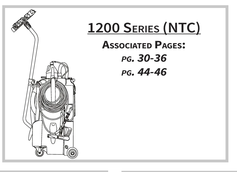
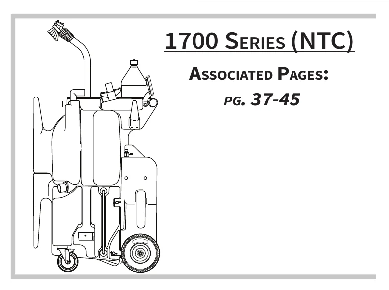
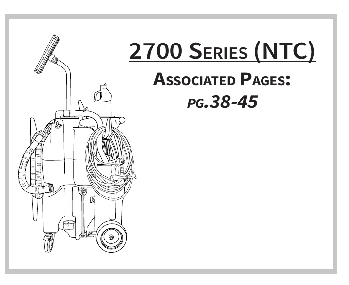
Identify your unit below to see the correct manual pages for your unit exploded view.
1.2 Warranty Registration
Thank you for purchasing a Kaivac product. Please take a few moments to register your product at kaivac.com/warranty.
Why register?
- Ensure your warranty coverage
- Simplify warranty service in the future with your information on file
- Be the first to know about upgrades, issues, new options and special offers.
Customer/Technical Support
1-800-287-1136
1.3 Limited Warranty Protection Plan
The Kaivac has been engineered and tested to provide long lasting performance. This warranty covers defects in workmanship or materials under normal use and service from the date of purchase.
Kaivac, Inc. warrants the following components to be free from defects in materials and workmanship for these time periods:
- Extended Warranty for end users who use only Kaivac chemicals for the life of the unit.
- 5 years on rotationally molded parts
- 3 years on other parts (excluding wear items)
- 1 year on labor
- Standard Warranty (for approved non-Kaivac chemicals)
- 1 year parts and labor
- Chemicals that have not been approved by Kaivac (If uncertain, please contact Kaivac to verify your chemical before using).
- No warranty
Battery Program Details
- Battery Warranty covers 2 years on a defective Battery.
- Battery Warranty covers the replacement of the Battery unit.
- Battery replacement remains under Warranty only for the remaining Warranty period of the original Battery unit (for a maximum of 2 years from the date of purchase of the unit).
WARRANTY LIMITATIONS:
- This warranty does not assume responsibility for damage or faulty performance caused by misuse or abuse, or where repairs or modifications have been made or attempted. Kaivac will make the final determination on whether the damage falls under this limited warranty for manufacturer’s defects.
- The following actions constitute misuse or neglect of the battery that void the warranty of the battery:
- Any modifications to Kaivac equipment may nullify any warranty
- Improper installation of the Quick Change battery
- Exposure to temperatures above and below the battery limits
- Use of any charger besides the supplied Kaivac® charger
- Dropping the battery box
- Long term storage of the battery without maintaining a battery charge of 25 to 40% capacity
- Under no circumstances will Kaivac be liable for any loss, damage, expenses or consequential damages arising in connection with the use or inability to use Kaivac’s product. This warranty is in lieu of any other warranty expressed or implied, including any warranty of merchantability or fitness for a particular purpose.
All Kaivac replacement parts are guaranteed for 90 days from the date of installation. Normal wear items such as wheels, hoses, seals, gaskets, cords, casters, squeegees and GFCI are excluded from warranty coverage.
All warranty claims must be accompanied by a Return Authorization Number (RAN), which is available by calling the Kaivac, Inc. Customer Service Department. No returns will be accepted without a RAN.
This warranty does not apply to return freight costs, damage or defect caused by accident, negligence, misuse, fire or repair done by anyone other than a Kaivac authorized repair center. In no event shall Kaivac, Inc. be liable for incidental or consequential damages, or any damages to persons or property.
Please Note: Under no circumstances will the seller be liable for any loss, damage, expenses or consequential damages arising in connection with the use or inability to use seller’s product. Kaivac, Inc. reserves the right to make changes or improvements to its equipment without notice. Some states do not allow the exclusion or limitation of incidental or consequential damages. This warranty is in lieu of any other warranty expressed or implied, including any warranty of merchantability or fitness for a particular purpose.
1.4 Important Safety Instructions
SAVE THESE INSTRUCTIONS
CONSULT KAIVAC.COM FOR THE MOST UP TO DATE SAFETY PRECAUTIONS
READ ALL INSTRUCTIONS BEFORE USING THIS UNIT
When using an electrical unit, basic precautions should always be followed, including the following:
GENERAL SAFETY INSTRUCTIONS (APPLICABLE TO CORDED AND BATTERY UNITS):
- For commercial use only.
- Use unit only as described in this Manual. Use only Kaivac’s recommended attachments.
- Follow the maintenance instructions specified in this Manual.
- For indoor use only.
- Store indoors.
- Stay alert - watch what you are doing.
- Keep operating area clear of all persons.
- Keep hair, loose clothing, fingers, and all parts of body away from openings and moving parts.
- NO COMBUSTIBLES! Sparks inside the motor can ignite flammable vapors or dust. Do not use unit near combustible liquids and gases, or to pick up explosive dusts or gasoline.
- Know how to stop the unit and bleed pressures quickly. Be thoroughly familiar with the unit’s controls before operating.
- DO NOT allow unit to be used as a toy and unit should not be operated by children. Close attention is necessary when used near children.
- Use extra care when cleaning on stairs.
- DO NOT operate the unit when fatigued or under the influence of alcohol or drugs.
- DO NOT put any object into unit’s openings. Do not use with any of the unit’s opening blocked; keep free of dust, lint, hair, and anything that may reduce air flow.
- DO NOT pick up anything that is burning or smoking, such as cigarettes, matches or hot ashes.
- DO NOT overreach or stand on unstable support. Keep good footing and balance at all times.
- DO NOT operate without the Vacuum Motor Float Cage installed. If float is removed, reinstall by screwing back into place.
- DO NOT use without filters in place.
- Personal Protective Equipment (PPE): It is recommended to wear proper personal protective equipment as required by the chemical product label instructions used in conjunction with the unit. For Kaivac chemical products, refer to product label.
SPRAY SYSTEM SAFETY INSTRUCTIONS:
- DO NOT spray liquid from the unit or attachments onto electrical outlets or any electrical devices.
- Risk of injection or injury to persons - DO NOT direct discharge stream at persons.
- INJECTION HAZARD: Unit can cause serious injury if the spray permeates the skin. Do not point the spray gun at anyone or any part of the body. In case of permeation, seek medical aid immediately.
- THIS UNIT IS CAPABLE OF PRODUCING 500 PSI (3447 kPa). To avoid rupture and injury, do not operate this pump with components rated less than 500 PSI (3447 kPa) working pressure (including but not limited to spray guns, hose, and hose connections); and before servicing, cleaning or removal of any part, shut off power and relieve pressure.
- High pressure cleaners, such as this unit, shall not be used by children, persons with reduced physical, sensory or mental capabilities or lack of experience and knowledge or untrained personnel. Children should not play with the unit. Cleaning and user maintenance should not be performed by children.
CORDED UNITS SAFETY INSTRUCTIONS (APPLICABLE TO CORDED UNITS):
- Inspect cord and plug prior to use. Do not use with damaged cord or plug. If unit is not working as it should, has been dropped, damaged, left outdoors or dropped into water, do not use or charge and return unit to a Kaivac service center.
- Test the unit’s ground fault circuit interrupter (GFCI) before each use.
- Turn off the unit before unplugging. Do not leave unit when plugged in. Unplug from outlet when not in use and before servicing.
- Turn off all controls before unplugging.
- Connect to a properly grounded outlet only. Do not remove ground pin on plug. See Grounding Instructions below.
- This unit may also have been provided with a ground fault circuit interrupter built into the power cord. If replacement of the plug or cord is needed, use only identical replacement parts.
- This unit comes with a grounded attachable extension cord. If cord is damaged, replace with equivalent 120v, 15amps, 14GA rated cord. This cord must be attached and mechanically secured using the provided cord connector to use the unit.
- The unit must be disconnected from any electrical or battery source when the unit is being cleaned or maintenance of unit or when replacing parts
- Keep all connections dry and off the ground.
- Keep the cord away from heated surfaces.
- If using extension cord with unit, make sure the connection is above and off the floor and away from exposure to liquid.
- DO NOT handle plug or unit with wet hands.
- DO NOT pull or carry by cord, use cord as handle, close a door on cord, or pull cord around sharp edges or corners. Do not run unit over cord. Keep cord away from heated surfaces.
- DO NOT unplug by pulling on cord. To unplug, grasp the plug, not the cord.
1.4 Important Safety Instructions (Continued)
SAVE THESE INSTRUCTIONS
CONSULT KAIVAC.COM FOR THE MOST UP TO DATE SAFETY PRECAUTIONS
READ ALL INSTRUCTIONS BEFORE USING (THIS UNIT)
When using an electrical unit, basic precautions should always be followed, including the following:
BATTERY UNITS SAFETY INSTRUCTIONS (APPLICABLE TO BATTERY UNITS):
- Never use a battery that has been damaged in any way. Damaged batteries may exhibit unpredictable behavior.
- Never use or charge a damaged battery pack.
- ONLY USE with Kaivac, Inc. battery, and charger.
- Inspect the battery before each use for damage, dents, cracks, or holes.
- If included with legacy unit, the battery splash cover must remain in place. Without the battery splash cover, the battery housing may become damaged which may cause the battery to malfunction, which can result a fire, explosion, personal injury, and/or property damage.
- If your unit contains a chemical-resistant plastic protective helmet, consult the Helmet Addendum for additional instructions and warnings.
- Exposure of units to airborne polyunsaturated fats in the food service industry may cause deterioration of battery components. Failure to inspect and use as instructed may result in fire explosion, personal injury, or property damage.
- Under certain conditions, including damage or liquid infiltrating the battery’s interior cells, the battery may emit smoke, sparks, or fire. Liquid may be ejected from the battery; avoid contact. If contact accidentally occurs, flush with water. If liquid contacts eyes, additionally seek medical help. Liquid ejected from the battery may cause irritation or burns.
- Stop use immediately if the battery or unit sparks or shows signs of fire. And may result in fire.
- If unit or battery emits fumes, smoke, sparks, or fire, discontinue use immediately. Do not touch battery. If unit can be safely moved, move outside to a well ventilated fire safe area away from people or combustible material.
- DO NOT attempt to repair, service or modify the batteries or charger. Contact Kaivac Technical Support with any issues.
- Disconnect the battery from the unit before making any adjustments, changing accessories, or storing unit. Such preventive safety measures reduce the risk of starting the unit accidentally.
- When charging battery, make sure charger or unit has at least 6 inches of clearance on all sides for adequate air flow.
- When battery is not in use, keep it away from other metal objects like paper clips, coins, keys, nails, screws or other small metal objects that can make a connection from one terminal to another. Connecting or shorting the battery terminals together may cause burns or a fire.
- Keep heat sources, sparks, and flames away from batteries.
- Prevent unintentional starting. Ensure the switch is in the off-position before connecting to battery, picking up or carrying the unit. Do not carry the unit with your finger on the switch. Energizing an unit that has the switch on invites accidents.
- DO NOT allow battery to be submerged in water.
- DO NOT use a battery that has been submerged in water, or if water has infiltrated the battery housing even if it appears to be working.
- DO NOT charge batteries outdoors.
- DO NOT short-circuit the battery or charger terminals with conductive items such as paper clips. This can deliver high current.
- DO NOT crush or drop the battery.
- DO NOT expose a battery or unit to fire or excessive temperature. Exposure to fire or temperature above 265ºF (130ºC) may cause explosion.
- DO NOT use or store the NTC System or battery in refrigerated areas, in environments when the battery is in direct contact with liquids, or near flammable or combustible materials.
- DO NOT charge or store battery for extended time (1 month or more) in temperatures below 40ºF (4ºC).
- DO NOT remove any part of the battery, charging unit, or unit: If your unit has a chemical-resistant plastic protective helmet, do not remove it.
- DO NOT plug battery in while Vacuum Motor is in ON position. It may damage the system.
- DO NOT incinerate the battery even if it is non-working or severely damaged. The battery can explode in a fire.
- DO NOT leave battery connected to charger once the charger light is green. Leaving battery on charger will diminish the life of the battery
- Never dispose of the battery in the trash. It is important that your old, damaged battery is disposed of and/or returned as instructed by Kaivac Customer Care/Technical Support at 1-800-287-1136.
1.4 Important Safety Instructions (Continued)
SAVE THESE INSTRUCTIONS
CONSULT KAIVAC.COM FOR THE MOST UP TO DATE SAFETY PRECAUTIONS
READ ALL INSTRUCTIONS BEFORE USING (THIS UNIT)
When using an electrical unit, basic precautions should always be followed, including the following:
CHARGER/ELECTRICAL WARNINGS:
- Inspect the charger, cords, and connections prior to each use.
- Follow all charging instructions and do not charge the battery or unit outside of the temperature range specified in the instructions. Charging improperly or at temperatures outside of the specified range may damage the battery and increase the risk of fire.
- Connect charging cord to a properly grounded outlet only. See Grounding Instructions.
- DO NOT use charger if it has a damaged cord or plug.
- DO NOT operate charger if it has received a sharp blow, been dropped, or damaged in any way.
- DO NOT handle charger, including charger plug and charger terminals, with wet hands while charger is plugged in or while inserting plug into electrical outlet.
- DO NOT leave charger plugged in when not in use.
- DO NOT plug in charger while Vacuum Head is in ON position. It may damage the unit’s electrical system.
- DO NOT pull on charger cord to unplug. Grasp and pull the plug, not the cord.
- DO NOT carry charger by cord.
1.5 Battery Information
Keep Batteries at Room Temperature: Store between 32 and 113 degrees F (0ºC to 45ºC). Avoid battery exposure to extreme temperatures. If shelving battery longer than (1) month, deplete battery to 50% charge during storage period (two bars on the battery indicator).
Batteries Lose Capacity Over Time: Batteries naturally deteriorate over time whether being used or not. If battery use instructions are properly followed, batteries deteriorate at a rate of approximately 10% run time per year but may vary by patterns of use.
Fully Discharge vs. Partial Discharge and the Effect on Battery Cycles: Unlike lead acid batteries, the Lithium-ion battery used with Kaivac equipment is not damaged by full or partial discharging. The expected battery hours of use are approximately 600 hours and 400 charge cycles. If you discharge battery only to 80%, then the user can expect to get more cycles (500 cycles). With dual batteries make sure to alternate batteries per charge in order to maximize for life capacity.
Extended Storage: It is recommended to discharge to 50% capacity (two bars on the battery indicator) and store in a cool location (between 32ºF to 113ºF or 0ºC to 45ºC). To avoid battery impact, store battery laying down on its side on lowest shelf, and secured. If battery is dropped or experiences an impact or damage, discontinue use and replace. Never use a damaged battery, as a damaged battery may act in an unpredictable manner resulting in fire, explosion, property damage, or personal injury.
Battery Gauge: The Kaivac provided battery comes with a built-in Battery Gauge or which shows the approximate run time for the current charge remaining.
Replacement - End of Life: Rechargeable batteries eventually wear out. When your Kaivac Battery run time is less than 55% (i.e. 50 minutes for non-quick change and 33 minutes for Quick Change batteries), Kaivac recommends replacing your battery. Regardless of run time, contact Kaivac to replace your battery after 4 years. Consult kaivac.com for information on recycling your old battery through a licensed disposal facility.
DO NOT DISCARD BATTERY INTO TRASH! It is important to recycle your old batteries at your local authorized battery recycling facility or by calling 1-800-USA-CLEAN (1-800-872-2532) and selecting Option 3.
| Battery Specifications | |
|---|---|
| Weight | With Box, 11 lbs. (4,9 kg) |
| Body Material | Injection Mold Polypropylene |
| Dimensions (H x W x D) | 18 x 7 x 5 in. (45,7 x 17,8 x 12,7 cm) |
| Voltage | 36V DC |
| Battery Capacity | 15 A-hr |
| Battery Current | 15 A DC |
| Battery Type | Lithium-Ion |
| Approx. Run Time BOL (Beginning of Life) | 60 minutes |
| Approx. Run Time EOL (End of Life) | 35 minutes (discontinue use and take to recycling center) |
| Battery Box Receptacle | IP65 / IP67 (not required for UL) |
| Run Time Hour Meter | Acts as “odometer for battery” and runs only when motor switch is ON |
| Approx. Charge Cycles | 400 @ 100% discharge / 500 @ 80% discharge |
| Cut off Voltage (fully discharged) | 30V |
| Charger Specifications | |
| Approx. Charge Time | 5 hours |
| Charger Amps | 4 Amps |
| Charge Voltage | 42V DC |
| Charger Voltage | 110-240VAC / 36VDC (240VAC version only needs correct plug for wall outlet) |
| Charging Robustness | No special instructions |
| Battery Charge Memory | None |
| Battery Charge Gauge | Yes, LED Indicator |
| Approx. Charge Cycles | 400 @ 100% discharge / 500 @ 80% discharge |
| Storage/Inventory: | |
| Storage & Operation Ambient Temp | 32ºF (0ºC) to 113ºF(45ºC) |
| Storage & Shipping Charge | 40-60% Charge (35-38VDC) |
1.6 Grounding Information
Grounding: Corded Units
GROUND FAULT CIRCUIT INTERRUPTER PROTECTION (for spray systems only)
If your unit is a corded unit, it has been supplied with a ground-fault circuit-interrupter(GFCI) built into the plug of the power-supply cord. This GFCI device provides additional protection from the risk of electric shock. Should replacement of the plug or cord become necessary, use only identical replacement parts that include GFCI protection.
If your unit is a corded unit, it is for use on a nominal circuit and has a grounding attachment plug. Make sure that the appliance is connected to an outlet having the same configuration as the plug. No adapter should be used with this unit.
GROUNDING INSTRUCTIONS
If your unit is a corded unit, it must be grounded. If the unit should malfunction or breakdown, grounding provides a path of least resistance for electric current to reduce the risk of electric shock. This unit is equipped with a cord having an equipment-grounding conductor and a grounding plug. The plug must be plugged into an appropriate outlet that is properly installed and grounded in accordance with all local electrical codes and ordinances.
Improper connection of the unit-grounding conductor can result in a risk of electric shock. Check with a qualified electrician or service person if you are in doubt as to whether the outlet is properly grounded. Do not modify the plug provided with the unit by removing the ground pin on the plug – if the plug will not fit the outlet, have a proper outlet installed by a qualified electrician.
This unit comes with a grounded attachable extension cord. If damaged, replace with Kaivac® (OEM) cord, or if necessary an equivalent cord rated 120V, 15 amps, 3-wire, 14 GA. This cord must be attached and mechanically secured using the provided cord connector to use the unit.
Grounding: Battery Units
GROUNDING INSTRUCTIONS
The charger must be grounded. If it should malfunction or breakdown, grounding provides a path of least resistance for electric current to reduce the risk of electric shock. This unit is equipped with a cord having equipment grounding conductor and grounding plug. The plug must be inserted into an appropriate outlet that is properly installed and grounded in accordance with all local codes and ordinances.
Improper connection of the unit-grounding conductor can result in a risk of electric shock. Check with a qualified electrician or service person if you are in doubt as to whether the outlet is properly grounded. Do not modify the plug provided with the unit by removing the ground pin on the plug – if the plug will not fit the outlet, have a proper outlet installed by a qualified electrician.
This unit is for use on a nominal circuit and has a grounding attachment plug. Make sure that the unit is connected to an outlet having the same configuration as the plug. No adapter should be used with this unit.
1.6 Grounding Information (Continued)
Make sure your extension cord is in good condition and is the correct size for your unit. Table 1 shows the correct size to use depending on cord length and nameplate ampere rating. If in doubt, use the next heavier gauge. The smaller the gage number, the heavier the cord. An undersized extension cord will cause a drop in line voltage resulting in loss of power and overheating.
Use only three-wire outdoor extension cords that have three-prong grounding receptacles that accept the unit’s plug.
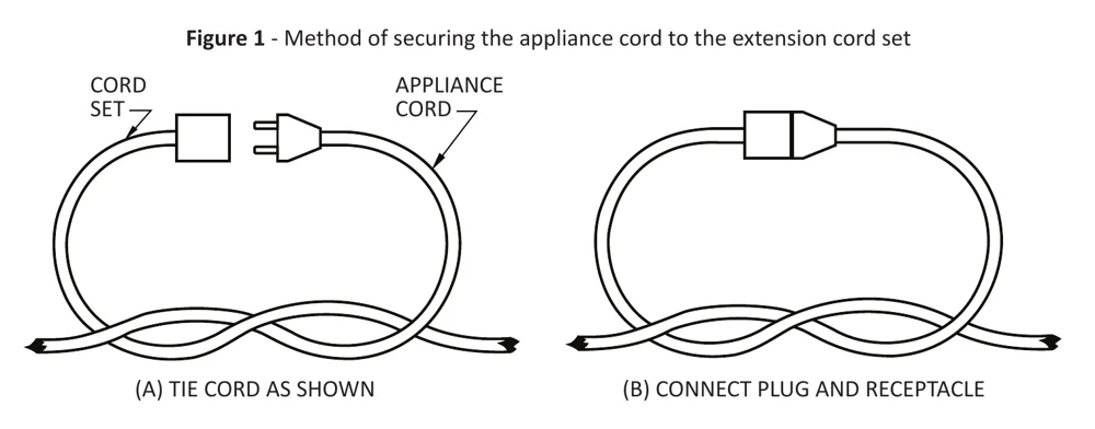
To reduce the risk of disconnection of the unit’s cord from the extension cord during operations:
- Make a knot as shown in Figure 1 below:
| Ampere rating | Volts | Total length of cord | ||||
|---|---|---|---|---|---|---|
| More than, A | Not more than, A | 120 V | 7.62 m (25 ft) | 15.24 m (50 ft) | 30.48 m (100 ft) | 45.72 m (150 ft) |
| mm² (AWG) | ||||||
| 0 | 6 | — | 0.82 (18) | 1.3 (16) | 1.3 (16) | 2.1 (14) |
| 6 | 10 | — | 0.82 (18) | 1.3 (16) | 2.1 (14) | 3.3 (12) |
| 10 | 12 | — | 0.82 (18) | 1.3 (16) | 2.1 (14) | 3.3 (12) |
Table 1 - Minimum gauge for extension cords
2.1 Battery Doc and Charging
Batteries and chargers: make sure your charger is compatible with your batteries, and set its charging algorithm to your battery pack before you use it.
Inspect battery, housing, plug, cord, splash cover (if applicable), and helmet (if applicable) for damage, including cracks, separation, dents, holes, missing, pieces, and fraying cord or wires. Do not use a damaged unit or a unit with a damaged battery. Check all cords, hoses, and spray lines for damage prior to use. If damage is found, do not continue until proper repairs are completed.
If using a legacy unit equipped with a fabric splash cover, ensure the cover is flipped over the battery top. Newer battery models may also be equipped with a chemical-resistant plastic protective helmet and fabric splash cover, ensure splash cover is flipped over helmet top.
Do not remove helmet.
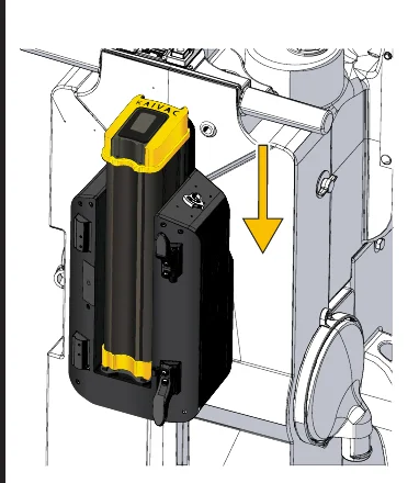
The bracket or housing mounted on the black box is where the battery will be mounted.
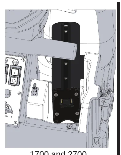
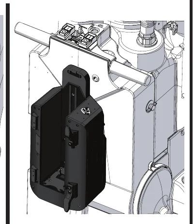
Place battery onto bracket rail, lowering it down into place. If unit is equipped with splash cover, place splash cover over top of battery.
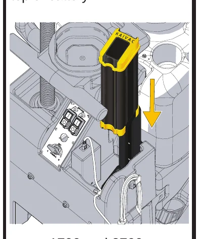
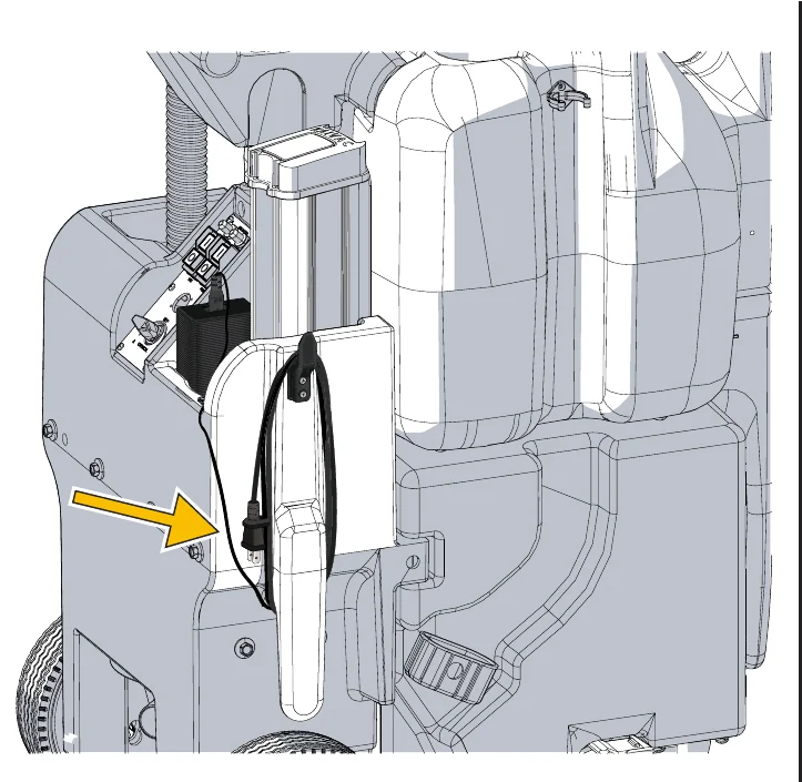
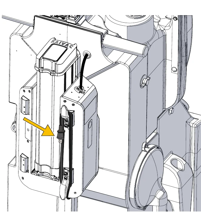
The Charging Cord is pointed out below. Plug into wall outlet to charge. Unplug when unit is in use.
2.2 Tool Arrangement
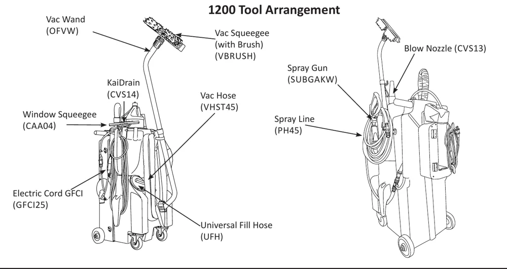
1200 Tool Arrangement
1700 and 2700 Tool Arrangement
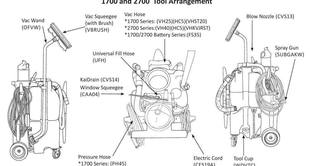
Vac Hose:
- *1700 Series: (VH25)(HC5)(VHST20)
- *2700 Series:(VH40)(HC5)(VHKVJRST)
- *1700/2700 Battery Series:(FS35)
Pressure Hose:
- *1700 Series: (PH45)
- *2700 Series:(PH75B)
2.3 Preparation For Use
Batteries and chargers: make sure your charger is compatible with your batteries, and set its charging algorithm to your battery pack before you use it.
- Unplug the charger from the battery if applicable.WARNING! RISK OF ELECTRIC SHOCK OR FIRE
Avoid getting water on the unit.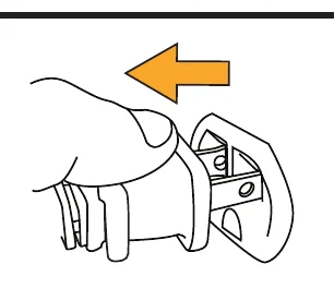
- Inspect battery, housing, plug, cord, splash cover (if applicable), and helmet (if applicable) for damage, including cracks, separation, dents, holes, missing, pieces, and fraying cord or wires.WARNING! RISK OF ELECTRIC SHOCK OR FIRE
Do not use a damaged unit or a unit with a damaged battery. Check all hoses and spray lines for damage prior to use. If damage is found, do not continue until proper repairs are completed.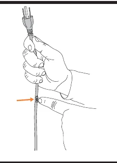
- Remove the water tank lid, or locate the Universal Fill Hose. Fill unit with clean, cool water.NOTICE Do NOT add chemical through this location of the unit.
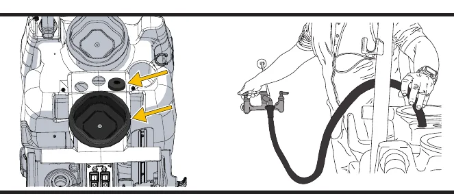
- Clean and spray the Float Cage located inside the Vacuum Tank. Ensure Float Cage is in place. Clean Float Cage regularly.CAUTION RISK OF INJURY
Do not use if Float Cage is not in place.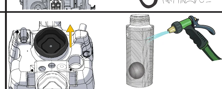
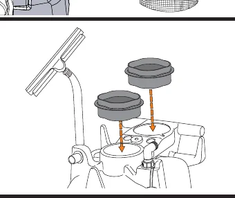
- Make sure Vac Lid Jug Holders are firmly on Vacuum Tank.
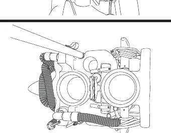
- Check unit for all tools and supplies needed to complete task. See Tool Arrangement in Section 2.2 of this manual.
2.3 Preparation For Use (Continued)
- Prepare the cleaning solution you will be using by attaching the chemical feed line and cap to the top of your chemical bottle. Then select the proper metering tip.
(See placard for metering tip information)NOTICE Use only Kaivac approved chemicals.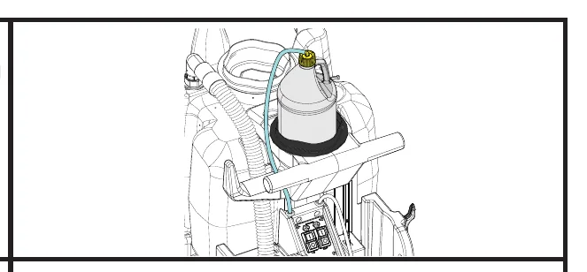
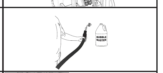
- If using a cleaning product that foams, use a foam inhibitor to cut excess. Pour 2 capfuls of inhibitor in the Vac Hose with Vac running to coat inside of Hose.CAUTION Risk of motor damage. Foaming chemicals in tank may damage Vac Motor.
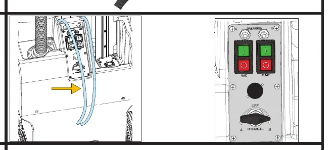
- If unit has chemical valve, when using unit with chemical jug, locate the valve on the switch panel. Turn valve to side “A” or side “B” depending on the chemical line connected to the jug. For no chemical, switch valve to “OFF” position.
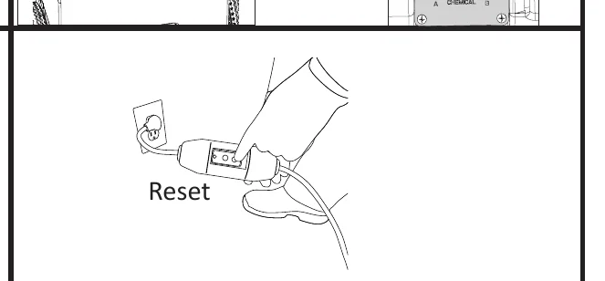
- If using a corded unit, plug in unit and test GFCI (Ground Fault Circuit Interrupter) to ensure it is working properly. You are now ready.
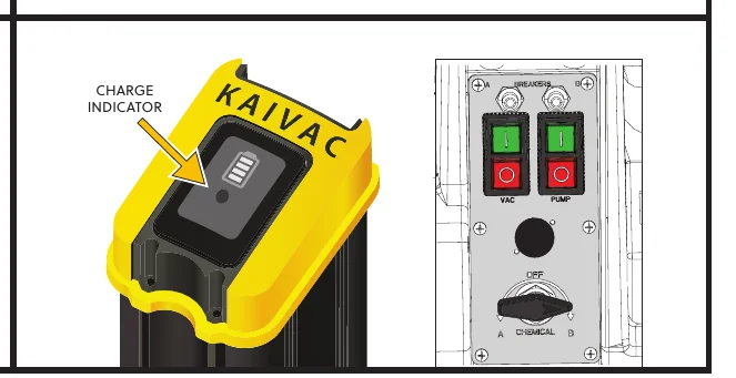
- If using a battery unit, ensure the battery is fully charged and in place. If unit is equipped with a splash cover, ensure it is in place over the battery. Power on unit using the switch panel, you are now ready.NOTICE Some battery models may contain a chemical-resistant plastic protective helmet. Do not remove helmet.
2.4 Unit Components
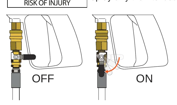
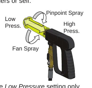
To turn Spray Gun off or on, switch the valve connected to Spray Gun as shown. The Spray Gun is connected to the Spray Line.
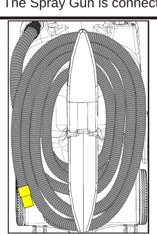
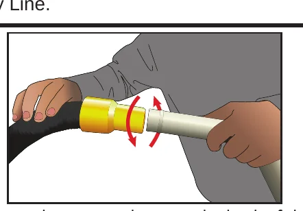
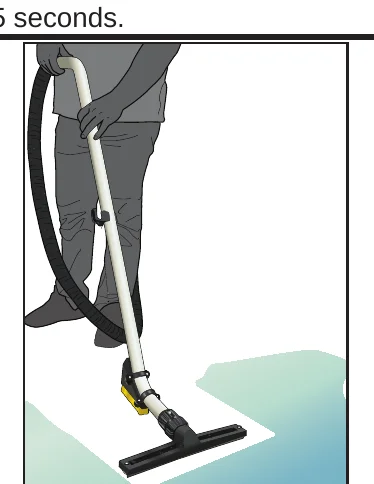
Locate the vacuum hose on the back of the unit. Ensure hose cuff is connected to the port at the top of the unit. Using the other end of the hose, attach the hose cuff to the vacuum wand and power on the unit to begin using floor squeegee.
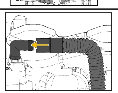
Ensure elbow hose is connected at top of unit.
Ensure dump hose is secured to cap-and-tether. Check this daily.
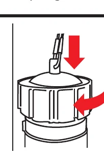
Dump excess from the vacuum tank by unscrewing the cap.
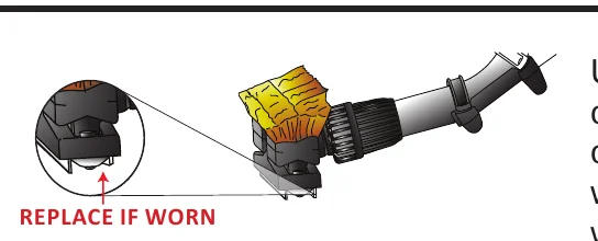
Check for worn squeegee blades. Worn blades cause streaking and loss of vacuum suction.
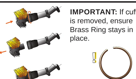
Unscrew cuff at end of Vac Wand, remove old head and replace with new every 6-8 weeks for optimal performance.
2.5 Filling The Unit
RISK OF FIRE, EXPLOSION, PROPERTY DAMAGE, OR SERIOUS INJURY OR DEATH
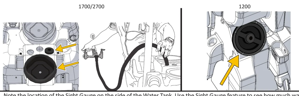
For No-Touch-Cleaning units, there are designated filling areas. The first area is accessed by running water through the Universal Fill Hose from a spigot. On the 1700/2700 models, the other is found by lifting the jug holder at the top of the unit that is connected to the Water Tank. Remove the jug holder to reveal the inside for the secondary fill location.
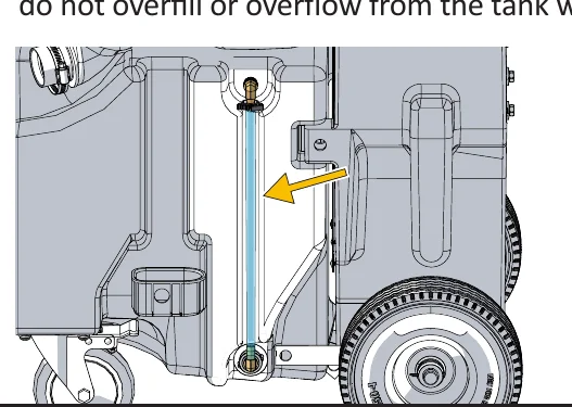
Note the location of the Sight Gauge on the side of the Water Tank. Use the Sight Gauge feature to see how much water is in the unit. If water is low, ensure you refill the tank by using the fill port. The Sight Gage will help see the water level, do not overfill or overflow from the tank will occur.
IF A CHEMICAL IS BEING USED, USE ONLY THE RECOMMENDED DILUTION. HIGH FOAMING CHEMICALS MAY CAUSE PREMATURE VAC MOTOR DAMAGE.
2.6 Emptying Vacuum Tank
If the Vacuum Motor shuts off before the job is complete, the Vacuum Tank may be full and need to be emptied. Lift the vac head jug holder on the top of the unit to see if tank is full. If unit is full or your job is complete, follow the instructions below to empty Tank into appropriate sink/drain.
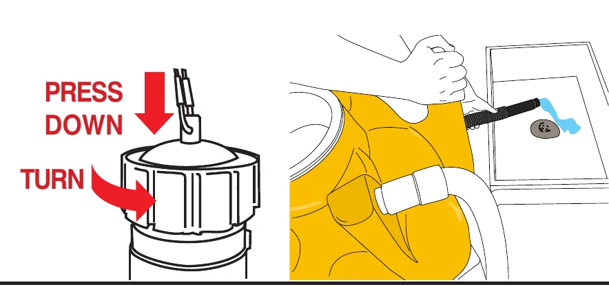
To begin the dumping process, you must first press down on the Dump Hose Cap and turn counter-clockwise. Once cap is removed, lower Dump Hose into appropriate sink/drain.
3.1 Unit & Battery Maintenance
| ITEM | PROCEDURE |
|---|---|
| Floor Squeegee |
|
| Spray Gun |
|
| Pressure Hose |
|
| Water Tank |
|
| Vacuum Tank |
|
| Leaks |
|
| Electrical System |
|
| Vacuum Wand |
|
| HEPA Filter |
|
| Float Cage |
|
| Battery Maintenance |
|
| Splash Cover (if included) |
|
3.2 Vacuum Diagram
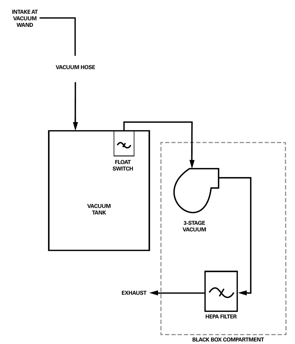
3.3 Pump Diagram
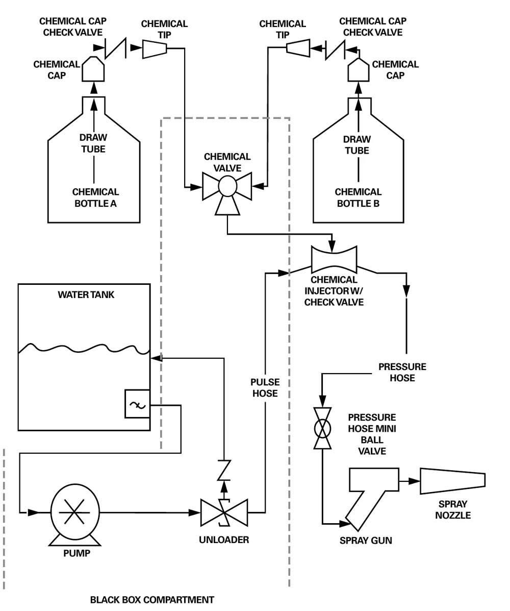
3.4 1250 AC Electrical Diagram
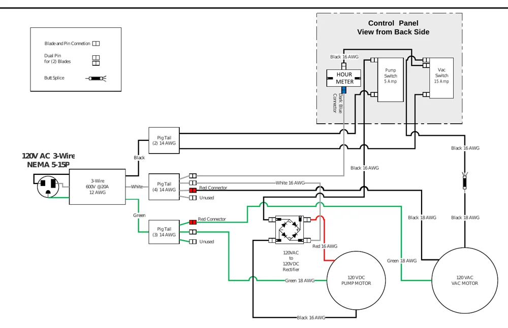
3.5 1250 Intl. AC Electrical Diagram
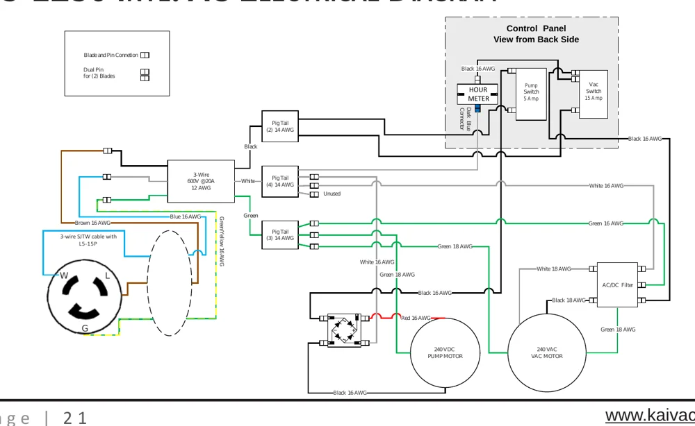
3.6 1250 DC Electrical Diagram
Batteries and chargers: make sure your charger is compatible with your batteries, and set its charging algorithm to your battery pack before you use it.
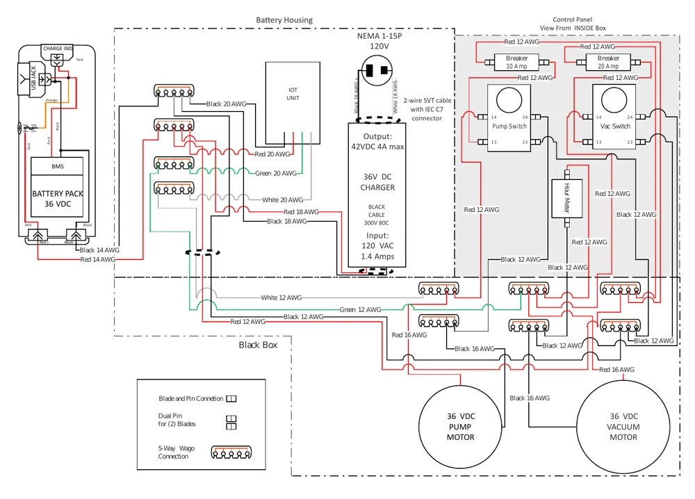
3.7 17/2750 AC Electrical Diagram
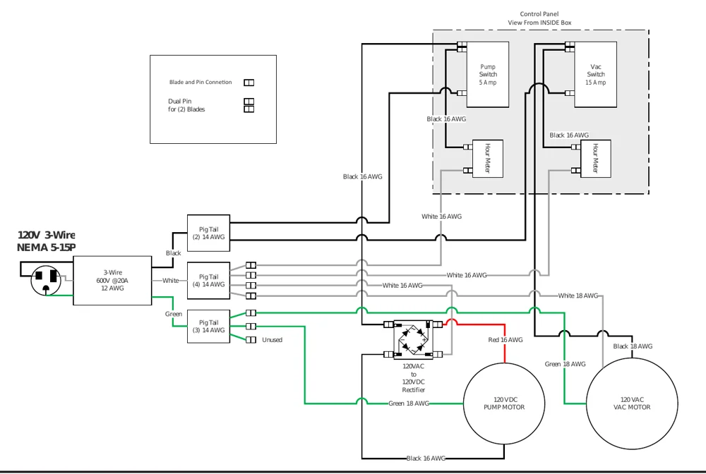
3.8 17/2750 Intl. AC Electrical Diagram
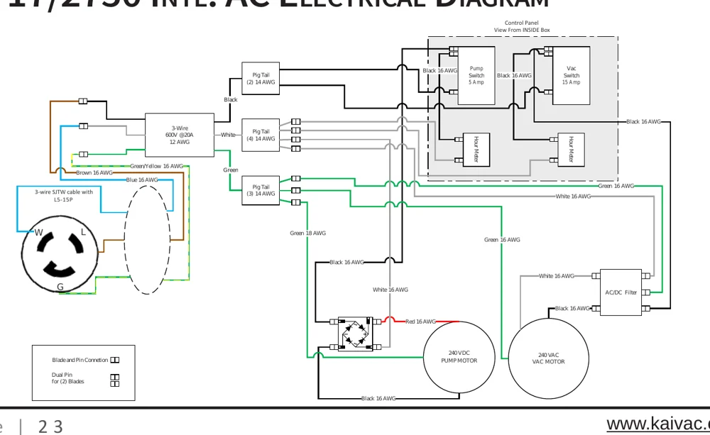
3.9 17/2750 DC Electrical Diagram
Batteries and chargers: make sure your charger is compatible with your batteries, and set its charging algorithm to your battery pack before you use it.
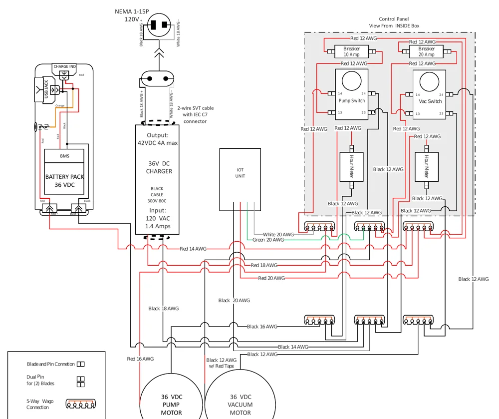
4.1 Troubleshooting Tips
Poor Vacuum Pickup
- Check Squeegee Blades. If blades are worn or damaged, replace Squeegee Head.
- Clean float cage.
- Check for leaks in the Vacuum Hose or Gasket.
- Check for clogged Vacuum Hose.
- Check to see if float ball was tripped.
Vacuum Shuts Off Prematurely
- Check Float Cage; clean if dirty.
- Cleaning Chemicals may be producing too much foam. Use correct Chemicals.
Other Issues? Contact Technical Support
Phone:
United States and Canada: 1-800-287-1136
International: 1-513-887-4600
Email:
For Technical Support Contact Form go to: https://www.kaivac.com/contactus.php and choose Technical Support tab.
4.2 Troubleshooting
Always unplug unit before inspecting or servicing.
| AREA | PROBLEM | POSSIBLE CAUSE | Remedy |
|---|---|---|---|
| Electrical | No Power to pump or vac motor | Unit not plugged in | Plug unit in |
| Switch not “on” | Check switches for “on” | ||
| GFCI tripped | Test and reset GFCI | ||
| Building circuit overloaded | Check and reset circuit | ||
| Switch wires loose | Disconnect power and check for loose wire | ||
| Connections loose | Disconnect power and check for loose wire under panel | ||
| Electrical burning smell WARNING! RISK OF FIRE, SERIOUS INJURY, OR DEATH TURN UNIT OFF IMMEDIATELY. | Vac motor brushes worn | Remove vac motor and repair | |
| Vac motor hung up | Release pressure on hose and jog vac switch, or replace | ||
| Pump motor hung up | Release pressure on hose and jog pump switch, or replace | ||
| Vacuum System | No/Weak vacuum | Vac tank full | Empty vac tank |
| Squeegee blades or wheels worn | Replace wheels or blades and check periodically | ||
| Float shutoff screen dirty | Spray off float screen to clean | ||
| Float ball stuck | Tap float and release/clean | ||
| Damaged hose | Cut and repair/replace | ||
| Dump hose plug missing | Contact dealer and replace | ||
| Access lid not right | Tighten lid hand tight | ||
| Vacuum hose plugged | Flush hose to remove debris | ||
| Too much liquid in vac hose | Allow air in when vacuuming | ||
| Vac hose still wrapped | Unwrap vac hose fully | ||
| Exhaust plugged | Clean exhaust port and HEPA filter | ||
| Leak in vac tank | If repairable, clean and dry affected area and seal with silicone | ||
| HEPA filter clogged | Remove HEPA filter and clean | ||
| Moisture from exhaust | Vac tank full | Dump vac tank | |
| Float shutoff missing | Replace | ||
| Excessive foam in vac tank | Use defoamer | ||
| Blow Dry System | No air flow | Hose disconnected | Reconnect hose |
| Moisture from exhaust | Water in blow hose | Dry blow line | |
| Suction, not blow action | Vacuum hose connected to vac tank | Reconnect to vac motor exhaust hose |
4.2 Troubleshooting (Continued)
| AREA | PROBLEM | POSSIBLE CAUSE | SOLUTION |
|---|---|---|---|
| High Pressure System WARNING Always unplug unit before inspecting or servicing. RISK OF ELECTRICAL SHOCK, FIRE, SERIOUS INJURY, OR DEATH | No water from pump or low pressure | Out of water | Fill water tank |
| Gun nozzle plugged | Remove orifice with Allen wrench and clean | ||
| Air in pump (vapor lock) | Use power prime technique | ||
| Gun orifice missing | Replace orifice | ||
| Water tank filter plugged | Clean tank and filter | ||
| In-line bowl filter plugged | Remove filter cover and clean | ||
| Bowl filter lid loose | Gently tighten bowl cover | ||
| Pressure hose damaged | Repair or replace | ||
| Quick disconnect leaking | Tighten or replace | ||
| Injector plugged | Remove safety cap from chemical and blow small amounts of compressed air into line | ||
| Pulse hose damaged | Repair or replace | ||
| Regulator failed | Replace | ||
| Hose kinked | Unkink and check for damage | ||
| Seals in pump need replaced | Remove and replace seals | ||
| Bad fan pattern or pinpoint pattern on gun | Debris in nozzle | Remove orifice with Allen wrench and clean | |
| Orifice damaged | Remove and replace | ||
| Chemical Injection System WARNING Always unplug unit before inspecting or servicing. RISK OF ELECTRICAL SHOCK, FIRE, SERIOUS INJURY, OR DEATH | No chemical flow | Out of chemical | Refill chemical |
| Safety cap not secure | Check safety cap/tighten | ||
| Chemical valve “off” | Check on/off valve | ||
| Safety cap plugged | Replace cap | ||
| Spray gun in wrong mode | Make sure gun nozzle is pulled out away from gun chemical mode | ||
| Metering tip plugged | Check metering tip for clog | ||
| Injector plugged | Remove safety cap from chemical and blow small amounts of compressed air into line | ||
| Air entering system | Check for air entering system around chemical lines or injector | ||
| Injector installed backwards | If fluttering or pulsing sound can be heard while spraying or when unit is running, it is possible that your injector is in backwards. Remove; reinstall. | ||
| Kink in chemical line | Replace chemical line |
4.2 Troubleshooting (Continued)
| AREA | PROBLEM | POSSIBLE CAUSE | SOLUTION |
|---|---|---|---|
| Chemical Injection System continued | Not enough chemical | Metering tip plugged | Remove and clean |
| Wrong metering tip | Check and replace per chart | ||
| Chemical line blows off safety cap | Debris in injector | Remove safety cap from chemical and blow small amounts of compressed air into line | |
| Water back flows into chemical bottle | Bad seat on injector check valve | Check injector o-ring or replace | |
| Bad safety cap | Replace safety cap | ||
| Dump System | Dump hose will not empty tank | Dump hose cap not removed | Remove cap |
| Clog in bottom of tank | Tip dump contents, remove debris | ||
| Dump hose leaks | Hose cut | If leak is less than 4” from tank side, cut and reattach, or replace | |
| Clamp loose | Tighten hose clamp | ||
| Dump cap missing | Replace cap | ||
| Wheels and Casters | Wheels will not roll; rubbing | Flat tires | Inflate tires to 30 p.s.i. |
| Debris wrapped around axle | Check for debris on axle | ||
| Bearings tight | Grease bearings | ||
| Wheels too loose on axle | Remove wheel, add washers to take up slack | ||
| Bearings falling out | Replace bearing assembly | ||
| Squeegee Head | Floor streaks | Worn blades or wheels | Replace wheels and/or blades |
| Squeegee head does not easily rotate when installed on wand | Brass ring on wand not in groove | Loosen coupling nut and re-position head on groove | |
| Coupling nut too tight | Loosen 1/2 turn | ||
| Head will not stay on wand | Coupling nut cracked | Replace | |
| Brass ring worn | Replace | ||
| Premature blade wear | Squeegee wheels worn | Check wheels for wear/replace | |
| Sucks to the floor too tightly | Squeegee wheels worn | Check wheels for wear/replace | |
| Battery WARNING RISK OF FIRE, EXPLOSION, AND SERIOUS INJURY, OR DEATH | Sparks/Burning/Fire/Smoke STOP USE IMMEDIATELY | Damage to battery or charger | Stop use immediately. Disconnect battery from charger, if possible. Unplug charger, if possible. |
Kaivac and KaiVac are trademarks of Kaivac, Inc. Southeastern Equipment & Supply is an independent dealer.