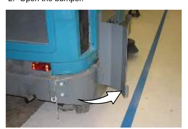
Free Shipping on Equipment & Parts orders of $200 or more! * Click for Restrictions

Have a question? 800-440-6723 International: 803-252-0100

English Se habla español
Parts › PartFinder › Tennant S30 Diesel › Operator manual
Form 9004087, Rev. 09 (4-2015)
Tennant · Ride-on sweeper

Tennant S30 Diesel Operator Manual

9004087 Rev. 09 (4-2015)74 pagesS30 (Diesel) Sweeper, North America / International; covers S/N 000000-006500 and 006501- variants
Free to read, no account neededEvery page has its own linkPart numbers link to the part
COVER

S30 (Diesel) Sweeper Operator Manual

SweepMax® Plus
TennantTrue® Parts
IRIS® a Tennant Technology‌‌​⁠‍⁠​​⁠⁠‍‌‌‍‍‌⁠‍‌​​​​​​​​‌​​​‌​⁠​​⁠⁠‍‌‍​‍⁠​​⁠​‍⁠⁠‍‌‌‍⁠‍⁠​​

North America / International

For the latest parts manuals and other language Operator manuals, visit: www.tennantco.com/manuals

9004087
Rev. 09 (4-2015)
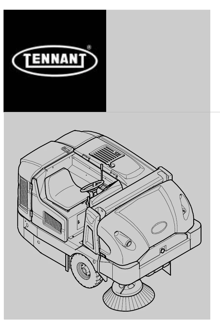
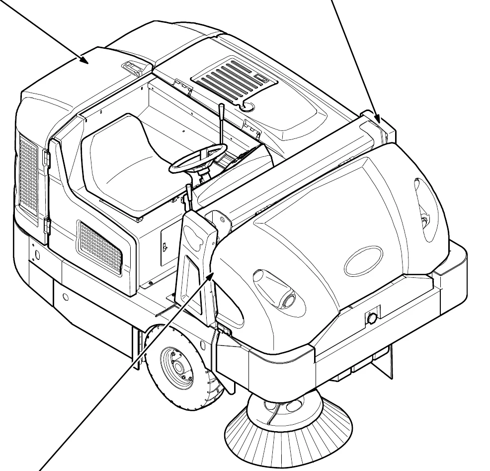
Cover illustration of the Tennant S30 diesel ride-on sweeper seen from the front left, showing the operator seat, steering wheel, engine cover, hopper cover, front wheel and side brush
Source: Tennant S30 Diesel Operator Manual 9004087 Rev. 09 (4-2015), page 1, used with permission. SES ref PF-P3YP-FB3F‌‌​⁠‍⁠​​⁠⁠‍‌‌‍‍‌⁠‍‌​​​​​​​​‌​​​‌​⁠​​⁠⁠‍‌‍​‍⁠​​⁠​‍⁠⁠‍‌‌‍⁠‍⁠​​
S30 Diesel 9004087 (Rev. 09 (4-2015))Page 1 of 74
INTRODUCTION

INTRODUCTION

In short This introduction explains that the manual provides the operation and maintenance instructions for the machine and should be read completely before operating or servicing it. It also describes the intended use of the S30 and has space to record the model, serial number and installation date.‌‌​⁠‍⁠​​⁠⁠‍‌‌‍‍‌⁠‍‌​​​​​​​​‍​​​‌​⁠​​‌‍​‌⁠‍‌‍‍⁠⁠​⁠​‌​⁠‍‌‌⁠‌‌‍

This manual is furnished with each new model. It provides necessary operation and maintenance instructions.‌‌​⁠‍⁠​​⁠⁠‍‌‌‍‍‌⁠‍‌​​​​​​​​‍​​​‌​⁠​​‌‍​‌⁠‍‌‍‍⁠⁠​⁠​‌​⁠‍‌‌⁠‌‌‍

Open manual with an information symbol next to a round icon of a person reading a manual, indicating to read the manual before operating
Read this manual completely and understand the machine before operating or servicing it.

This machine will provide excellent service. However, the best results will be obtained at minimum costs if:

  • The machine is operated with reasonable care.
  • The machine is maintained regularly - per the machine maintenance instructions provided.
  • The machine is maintained with manufacturer supplied or equivalent parts.
Crossed-out wheeled waste bin symbol above a black bar, and a recycling symbol of three chasing arrows

PROTECT THE ENVIRONMENT

Please dispose of packaging materials, old machine components and fluids in an environmentally safe way according to local waste disposal regulations.

Always remember to recycle.

MACHINE DATA

Please fill out at time of installation for future reference.

Model No. −

Serial No. −

Installation Date −

INTENDED USE

The S30 is an industrial rider machine designed to sweep hard surfaces (concrete, asphalt, stone, synthetic, etc). Typical applications include industrial warehouses, manufacturing facilities, distribution facilities, stadiums, arenas, convention centers, parking facilities, transportation terminals, and construction sites. Do not use this machine on soil, grass, artificial turf, or carpeted surfaces. This machine can be used both indoors and outdoors, but ensure there is adequate ventilation if used indoors. Do not use this machine other than described in this Operator Manual.

Tennant Company
PO Box 1452
Minneapolis, MN 55440
Phone: (800) 553−8033 or (763) 513−2850
www.tennantco.com

CALIFORNIA PROPOSITION 65 WARNING: Engine exhaust from this product contains chemicals known to the State of California to cause cancer, birth defects, or other reproductive harm.

Thermo−Sentry, 1−STEP, EasyOpen, MaxPro, InstantAccess, II−Speed, Perma−Filter, Duramer, Lower Total Cost of Ownership, Touch−N−Go, Watershield Dust Control, and Cab Forward ErgoSpace are trademarks of Tennant Company.

Specifications and parts are subject to change without notice.

Original Instructions, Copyright © 2008, 2009, 2010, 2012, 2013, 2014, 2015 TENNANT Company, Printed in U.S.A.

Source: Tennant S30 Diesel Operator Manual 9004087 Rev. 09 (4-2015), page 2, used with permission. SES ref PF-IHFZ-EE2G‌‌​⁠‍⁠​​⁠⁠‍‌‌‍‍‌⁠‍‌​​​​​​​​‍​​​‌​⁠​​‌‍​‌⁠‍‌‍‍⁠⁠​⁠​‌​⁠‍‌‌⁠‌‌‍
S30 Diesel 9004087 (Rev. 09 (4-2015))Page 2 of 74
CONTENTS

CONTENTS

In short This page lists the manual's sections and topics with their page numbers, from Safety Precautions and Operation through Maintenance, including lubrication, hydraulics, engine, battery, fuses, brushes and skirts.‌‌​⁠‍⁠​​⁠⁠‍‌‌‍‍‌⁠‍‌​​​​​​​​⁠​​​‌​⁠​​⁠​​‍‌‌‍​​⁠‍​‍⁠‌⁠‍​​‍‌‍‌​
TopicPage
Safety Precautions3
Operation7
Machine Components7
Controls And Instruments8
Touch Panel (S30 XP and X4)9
Symbol Definitions10
Operation Of Controls11
Directional Pedal11
Brake Pedal11
Parking Brake Pedal11
Steering Column Tilt Pedal11
Fuel Gauge12
Hour Meter13
Supervisor Control Buttons (S30 XP and X4)13
Engine Speed Controls13
Vacuum Fan Controls (S30)14
Vacuum Fan Controls (S30 XP and X4)14
Contrast Control Button (S30 Xp And X4)14
Filter Shaker Control (S30)15
Filter Shaker Control (S30 XP and X4)15
Operating / Hazard Light Switch15
Side Brush Light Switch (Option)15
Hopper Access Door16
Operator Seat17
Deluxe Suspension Seat17
Seat Belts17
Brush Information18
How The Machine Works18
Pre−Operation Checklist19
Starting The Machine20
Turning Off The Machine20
While Operating The Machine21
Sweeping (S30)22
Sweeping (S30 XP and X4)23
Emptying The Hopper24
Engaging The Hopper Support Bar25
Disengaging The Hopper Support Bar26
Display Module Fault Indicators (S30)27
Fault Indicator(s) (S30 XP and X4)28
Dash Fault Indicators29
Options30
Wand (Option)30
Heater / Air Conditioner Controls (Option)31
Windshield Wiper Switch (Option)31
Cab Light Switch (Option)31
Tower Bumpers (Option)32
Turn Signal Switch (Option)32
Machine Troubleshooting33
TopicPage
Maintenance35
Maintenance Chart35
Lubrication38
Engine Oil38
Rear Wheel Support (S30 and S30 XP)38
Steering Cylinder Bearing (S30 and S30 XP)38
Hopper Lift Arm Bearings38
Steering Rod End (S30 X4)39
Steering Spindles (S30 X4)39
Front Wheel Bearings39
Hydraulics40
Hydraulic Fluid41
Hydraulic Hoses41
Engine42
Cooling System42
Air Filter Indicator44
Air Filter44
Fuel Filter45
Fuel Lines45
Priming The Fuel System46
Engine Belt46
Battery46
Fuses And Relays47
Relay Panel Fuses And Relays47
Engine Harness Relays48
Cab Fuses (Cab Option)48
Removing And Inspecting The Dust Filter (SN 000000 − 006500)49
Removing And Inspecting The Dust Filter (SN 006501 − )50
Cleaning The Dust Filter51
Cleaning The Cyclone Assembly (SN 006501 − )51
Main Brush52
Replacing Or Rotating The Main Brush52
Checking The Main Brush Pattern54
Adjusting The Main Brush Taper54
Adjusting The Main Brush Width55
Side Brush55
Replacing The Side Brush55
Adjusting The Side Brush Pattern56
Rotating And Replacing The Side Brush Guard56
Skirts And Flaps57
Hopper Skirts57
Brush Door Skirts57
Rear Skirts57
Recirculation Flap57
Source: Tennant S30 Diesel Operator Manual 9004087 Rev. 09 (4-2015), page 3, used with permission. SES ref PF-A3Y4-FZ7Q‌‌​⁠‍⁠​​⁠⁠‍‌‌‍‍‌⁠‍‌​​​​​​​​⁠​​​‌​⁠​​⁠​​‍‌‌‍​​⁠‍​‍⁠‌⁠‍​​‍‌‍‌​
S30 Diesel 9004087 (Rev. 09 (4-2015))Page 3 of 74
CONTENTS

CONTENTS

TopicPage
Seals58
Brush Door Seals58
Hopper Seals58
Hopper Inspection Door Seals58
Filter Chamber Inlet Seal58
Cyclonic Pre−Filter Seals59
Dust Return Seals (SN 000000 − 006500)59
Dust Filter Seals (SN 000000 − 006500)59
Vacuum Wand Door Seals (Option)59
Cyclonic Dust Tray Seals (SN 006501 − )60
Cyclone Perma−Filter (SN 006501 − )60
Cyclone Cover Seals (SN 006501 − )60
Cyclone Cover Access Port Seal (SN 006501 − )60
Hopper Dust Filter Cover Seal (SN 006501 − )60
Brakes And Tires61
Brakes61
Tires61
Rear Wheel61
Propelling Motor61
Pushing, Towing, And Transporting The Machine62
Pushing Or Towing The Machine62
Transporting The Machine62
Machine Jacking64
Storage Information64
Specifications65
General Machine Dimensions/Capacities65
General Machine Performance65
Hydraulic System66
Steering66
Power Type66
Tires66
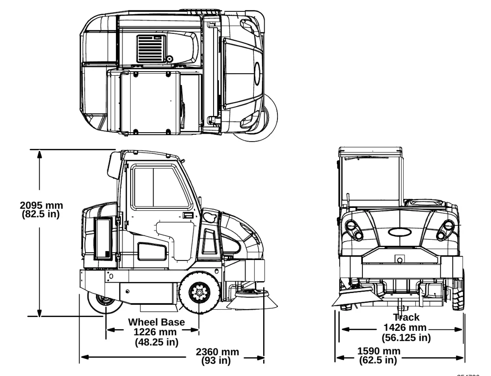
Machine Dimensions67
Index68
Source: Tennant S30 Diesel Operator Manual 9004087 Rev. 09 (4-2015), page 4, used with permission. SES ref PF-TRNS-R5D3‌‌​⁠‍⁠​​⁠⁠‍‌‌‍‍‌⁠‍‌​​​​​​​‌​​​​‌​⁠​​​‍‍‌​‍‌​‌⁠​‍⁠⁠‌‍‍​⁠⁠‍‌​‌
S30 Diesel 9004087 (Rev. 09 (4-2015))Page 4 of 74
SAFETY PRECAUTIONS

SAFETY PRECAUTIONS

IMPORTANT SAFETY INSTRUCTIONS - SAVE THESE INSTRUCTIONS

In short This section explains the warning, caution and "for safety" signals used in the manual and lists the hazards marked on the machine. It also lists what the operator must not do, and must check, before and when starting the machine.‌‌​⁠‍⁠​​⁠⁠‍‌‌‍‍‌⁠‍‌​​​​​​​‌‌​​​‌​⁠​​‌‍​‍​​‍‌‍‍‌‍⁠‍​​‌​​‌‌‌‍‌

The following precautions are used throughout this manual as indicated in their description:‌‌​⁠‍⁠​​⁠⁠‍‌‌‍‍‌⁠‍‌​​​​​​​‌‌​​​‌​⁠​​‌‍​‍​​‍‌‍‍‌‍⁠‍​​‌​​‌‌‌‍‌

Warning symbol: black triangle with an exclamation mark, shown beside the WARNING definition
WARNING: To warn of hazards or unsafe practices that could result in severe personal injury or death.
Caution symbol: black triangle with an exclamation mark, shown beside the CAUTION definition
CAUTION: To warn of unsafe practices that could result in minor or moderate personal injury.

FOR SAFETY: To identify actions that must be followed for safe operation of equipment.

The following information signals potentially dangerous conditions to the operator. Know when these conditions can exist. Locate all safety devices on the machine. Report machine damage or faulty operation immediately.

Column of black warning triangle symbols with exclamation marks, one beside each machine hazard warning
WARNING: Moving belt and fan. Keep away.
WARNING: Machine emits toxic gases. Serious injury or death can result. Provide adequate ventilation.
WARNING: Raised hopper may fall. Engage hopper support bar.
WARNING: Lift arm pinch point. Stay clear of hopper lift arms.
WARNING: Burn hazard. Hot surface. Do NOT touch.
WARNING: Accident may occur. Do not operate vacuum or blower wand while driving.
WARNING: This product contains chemicals known to the State of California to cause cancer, birth defects, or other reproductive harm.

This machine may be equipped with technology that automatically communicates over the cellular network. If this machine will be operated where cell phone use is restricted because of concerns related to equipment interference, please contact a Tennant representative for information on how to disable the cellular communication functionality.

FOR SAFETY:

  1. Do not operate machine:
    • Unless trained and authorized.
    • Unless operator manual is read and understood.
    • Under the influence of alcohol or drugs.
    • While using a cell phone or other types of electronic devices.
    • Unless mentally and physically capable of following machine instructions.
    • If it is not in proper operating condition.
    • Without filters in place.
    • In areas where flammable vapors/liquids or combustible dusts are present.
    • In areas that are too dark to safely see the controls or operate the machine unless operating / headlights are turned on.
    • In areas with possible falling objects unless equipped with overhead guard.
  2. Before starting machine:
    • Check machine for fluid leaks
    • Keep sparks and open flame away from refueling area.
    • Make sure all safety devices are in place and operate properly.
    • Check brakes and steering for proper operation.
    • Adjust seat and fasten seat belt (if equipped).
  3. When starting machine:
    • Keep foot on brake and directional pedal in neutral.
Source: Tennant S30 Diesel Operator Manual 9004087 Rev. 09 (4-2015), page 5, used with permission. SES ref PF-MIHB-VSUZ‌‌​⁠‍⁠​​⁠⁠‍‌‌‍‍‌⁠‍‌​​​​​​​‌‌​​​‌​⁠​​‌‍​‍​​‍‌‍‍‌‍⁠‍​​‌​​‌‌‌‍‌
S30 Diesel 9004087 (Rev. 09 (4-2015))Page 5 of 74
SAFETY PRECAUTIONS

SAFETY PRECAUTIONS

In short This page lists safety rules for using the machine, leaving or servicing it, and loading it onto or off a truck or trailer. It also shows the protective equipment symbols for hearing, hands, eyes and dust.‌‌​⁠‍⁠​​⁠⁠‍‌‌‍‍‌⁠‍‌​​​​​​​‌‍​​​‌​⁠​​‍​​⁠‍‍‍​⁠‍‌​‌​‍‍⁠⁠⁠‌‌​‍​
  1. When using machine:
    • Use only as described in this manual.
    • Do not pick up burning or smoking debris, such as cigarettes, matches or hot ashes
    • Use brakes to stop machine.
    • Go slow on inclines and slippery surfaces.
    • Do not sweep on ramp inclines that exceed 14% grade or transport (GVWR) on ramp inclines that exceed 17% grade.
    • Reduce speed when turning.
    • Keep all parts of body inside operator station while machine is moving.
    • Always be aware of surroundings while operating machine.
    • Use care when reversing machine.
    • Move machine with care when hopper is raised.
    • Do not raise hopper when machine is on an incline.
    • Make sure adequate clearance is available before raising hopper.
    • Keep children and unauthorized persons away from machine.
    • Do not carry passengers on machine.
    • Always follow safety and traffic rules.
    • Report machine damage or faulty operation immediately.
  2. Before leaving or servicing machine:
    • Do not park near combustible materials, dusts, gases, or liquids.
    • Stop on level surface.
    • Set parking brake.
    • Turn off machine and remove key.
  3. When servicing machine:
    • All work must be done with sufficient lighting and visibility.
    • Keep work area well ventilated.
    • Avoid moving parts. Do not wear loose clothing, jewelry and secure long hair.
    • Block machine tires before jacking machine up.
    • Jack machine up at designated locations only. Support machine with jack stands.
    • Use hoist or jack that will support the weight of the machine.
    • Do not push or tow the machine without an operator in the seat.
    • Do not power spray or hose off machine near electrical components.
    • Disconnect battery connections before working on machine.
    • Avoid contact with battery acid.
    • Avoid contact with hot engine coolant.
    • Do not remove cap from radiator when engine is hot.
    • Allow engine to cool.
    • Keep flames and sparks away from fuel system service area. Keep area well ventilated.
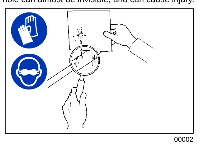
    • Use cardboard to locate leaking hydraulic fluid under pressure.
    • All repairs must be performed by a trained service mechanic.
    • Do not modify the machine from its original design.
    • Use Tennant supplied or approved replacement parts.
    • Wear personal protective equipment as needed and where recommended in this manual.

Blue round safety symbol showing a head wearing ear protection

For Safety: wear hearing protection.‌‌​⁠‍⁠​​⁠⁠‍‌‌‍‍‌⁠‍‌​​​​​​​‌‍​​​‌​⁠​​‍​​⁠‍‍‍​⁠‍‌​‌​‍‍⁠⁠⁠‌‌​‍​

Blue round safety symbol showing a gloved hand

For Safety: wear protective gloves.

Blue round safety symbol showing a face wearing eye protection goggles

For Safety: wear eye protection.

Blue round safety symbol showing a face wearing a dust mask

For Safety: wear protective dust mask.

  1. When loading/unloading machine onto/off truck or trailer:
    • Empty debris hopper before loading machine.
    • Turn off machine and remove key.
    • Use ramp, truck or trailer that will support the weight of the machine and operator.
    • Do not load/unload on ramp inclines that exceed 25% grade.
    • Use winch. Do not drive the machine onto/off the truck or trailer unless the load height is 380 mm (15 in) or less from the ground.
    • Set parking brake after machine is loaded.
    • Block machine tires.
    • Tie machine down to truck or trailer.
Source: Tennant S30 Diesel Operator Manual 9004087 Rev. 09 (4-2015), page 6, used with permission. SES ref PF-ONRO-YF7Q‌‌​⁠‍⁠​​⁠⁠‍‌‌‍‍‌⁠‍‌​​​​​​​‌‍​​​‌​⁠​​‍​​⁠‍‍‍​⁠‍‌​‌​‍‍⁠⁠⁠‌‌​‍​
S30 Diesel 9004087 (Rev. 09 (4-2015))Page 6 of 74
SAFETY PRECAUTIONS

SAFETY PRECAUTIONS

In short This page shows where the safety labels are placed on the machine: toxic gas warning, moving belt and fan warning, read-the-manual label, and lift arm pinch point warning. Damaged labels must be replaced.‌‌​⁠‍⁠​​⁠⁠‍‌‌‍‍‌⁠‍‌​​​​​​​‌⁠​​​‌​⁠​​‍‌⁠​‍‌⁠‌‍​‍​⁠⁠‌‌‍‍​​⁠‌‍‌

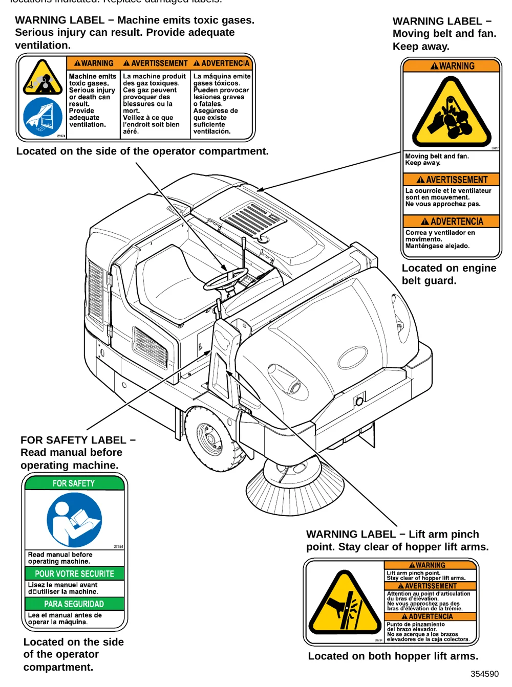
The safety labels appear on the machine in the locations indicated. Replace damaged labels.‌‌​⁠‍⁠​​⁠⁠‍‌‌‍‍‌⁠‍‌​​​​​​​‌⁠​​​‌​⁠​​‍‌⁠​‍‌⁠‌‍​‍​⁠⁠‌‌‍‍​​⁠‌‍‌

Drawing of the sweeper with arrows pointing to the locations of four safety labels: the toxic gases warning label and the FOR SAFETY read-manual label on the side of the operator compartment, the moving belt and fan warning label on the engine belt guard, and the lift arm pinch point warning label on both hopper lift arms, with each label shown enlarged
354590

WARNING LABEL − Machine emits toxic gases. Serious injury can result. Provide adequate ventilation.

Located on the side of the operator compartment.

WARNING LABEL − Moving belt and fan. Keep away.

Located on engine belt guard.

FOR SAFETY LABEL − Read manual before operating machine.

Located on the side of the operator compartment.

WARNING LABEL − Lift arm pinch point. Stay clear of hopper lift arms.

Located on both hopper lift arms.

Source: Tennant S30 Diesel Operator Manual 9004087 Rev. 09 (4-2015), page 7, used with permission. SES ref PF-Z63N-YQKU‌‌​⁠‍⁠​​⁠⁠‍‌‌‍‍‌⁠‍‌​​​​​​​‌⁠​​​‌​⁠​​‍‌⁠​‍‌⁠‌‍​‍​⁠⁠‌‌‍‍​​⁠‌‍‌
S30 Diesel 9004087 (Rev. 09 (4-2015))Page 7 of 74
SAFETY PRECAUTIONS

SAFETY PRECAUTIONS

In short This page shows where the warning labels are on the machine: burn hazard on the exhaust shield, raised hopper warnings on the hopper support bar and hopper lift arm, and an accident warning on the optional vacuum or blower wand door.‌‌​⁠‍⁠​​⁠⁠‍‌‌‍‍‌⁠‍‌​​​​​​​‍​​​​‌​⁠​​‌‌⁠​‍​‍‍⁠⁠‍‍​⁠⁠​‌​⁠⁠‍‌​​

WARNING LABEL − Burn hazard. Do NOT touch.‌‌​⁠‍⁠​​⁠⁠‍‌‌‍‍‌⁠‍‌​​​​​​​‍​​​​‌​⁠​​‌‌⁠​‍​‍‍⁠⁠‍‍​⁠⁠​‌​⁠⁠‍‌​​

Burn hazard warning label with a yellow triangle showing a hand over a hot surface, with text in English, French and Spanish

Located on the exhaust shield.

WARNING LABEL − Raised hopper may fall. Engage hopper support bar.
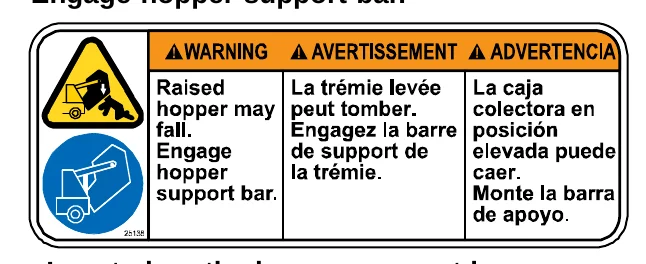
Raised hopper warning label with an icon of a falling hopper and a hopper support bar, with text in English, French and Spanish

Located on the hopper support bar.

Side view of the sweeper machine with arrows from the label locations to the exhaust shield, the hopper support bar and the hopper lift arm

WARNING LABEL − Raised hopper may fall. Engage hopper support bar.
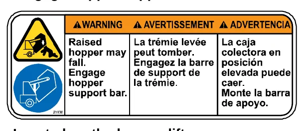
Raised hopper warning label with an icon of a falling hopper and a hopper support bar, with text in English, French and Spanish

Located on the hopper lift arm.

WARNING LABEL − Accident may occur. Do not operate vacuum or blower wand while driving.
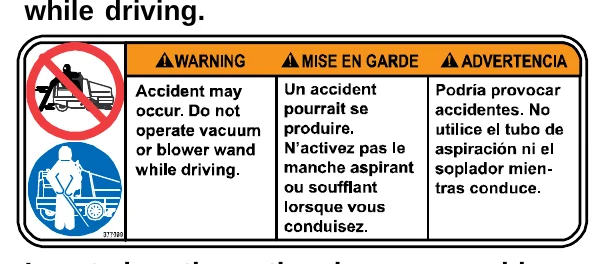
Accident warning label with a crossed-out vacuum wand icon while driving, with text in English, French and Spanish

Located on the optional vacuum or blower wand door.

354590

Source: Tennant S30 Diesel Operator Manual 9004087 Rev. 09 (4-2015), page 8, used with permission. SES ref PF-S2LA-FAG4‌‌​⁠‍⁠​​⁠⁠‍‌‌‍‍‌⁠‍‌​​​​​​​‍​​​​‌​⁠​​‌‌⁠​‍​‍‍⁠⁠‍‍​⁠⁠​‌​⁠⁠‍‌​​
S30 Diesel 9004087 (Rev. 09 (4-2015))Page 8 of 74
OPERATION

OPERATION

MACHINE COMPONENTS

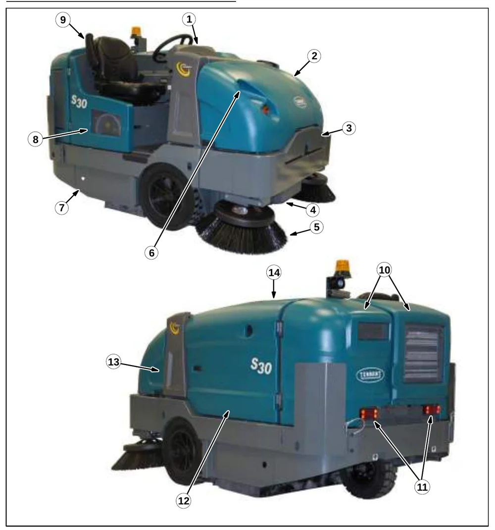
In short This page identifies the main parts of the S30 Diesel sweeper with two numbered photos, one from the front left and one from the rear right. The list below names each numbered component.‌‌​⁠‍⁠​​⁠⁠‍‌‌‍‍‌⁠‍‌​​​​​​​‍‌​​​‌​⁠​​​‍‍⁠‍‍‍‍‍‍‍‌‍​⁠​⁠⁠‍⁠‌​⁠‌
Two photos of the teal S30 Diesel sweeper with numbered callouts 1 to 14. The upper photo, a front left view, marks the instrument panel, front shroud, hopper access door, hopper, side brush, headlights, main brush access door, fuel tank and operator seat. The lower photo, a rear right view, marks the rear engine shroud, taillights, side shroud, hopper support bar and top cover.
No.Component
1Instrument panel
2Front shroud
3Hopper access door
4Hopper
5Side brush
6Headlights
7Main brush access door
8Fuel tank
9Operator seat
10Rear engine shroud
11Taillights
12Side shroud
13Hopper support bar
14Top cover
Source: Tennant S30 Diesel Operator Manual 9004087 Rev. 09 (4-2015), page 9, used with permission. SES ref PF-CKKO-3N5V‌‌​⁠‍⁠​​⁠⁠‍‌‌‍‍‌⁠‍‌​​​​​​​‍‌​​​‌​⁠​​​‍‍⁠‍‍‍‍‍‍‍‌‍​⁠​⁠⁠‍⁠‌​⁠‌
S30 Diesel 9004087 (Rev. 09 (4-2015))Page 9 of 74
OPERATION

OPERATION

CONTROLS AND INSTRUMENTS

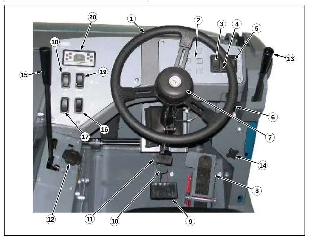
In short This page shows the operator controls and instruments with numbered callouts on a photo. The list below names each control, split between items for all models and items for the S30 only.‌‌​⁠‍⁠​​⁠⁠‍‌‌‍‍‌⁠‍‌​​​​​​​‍‍​​​‌​⁠​​‍‍‍‍‍​​⁠‍⁠⁠‍⁠‍​​​⁠‌⁠​​‍⁠
Photo of the operator compartment with callouts 1 to 20: steering wheel, dash fault indicator lights, wand and light switches, ignition switch, horn button, directional pedal, brake pedal, parking brake pedal, steering column tilt pedal, main brush adjustment knob, side brush lever and adjustment knob, main brush lever, hopper door and raise/lower switches, engine speed switch, vacuum fan/filter shaker switch and indicator panel

(All models)‌‌​⁠‍⁠​​⁠⁠‍‌‌‍‍‌⁠‍‌​​​​​​​‍‍​​​‌​⁠​​‍‍‍‍‍​​⁠‍⁠⁠‍⁠‍​​​⁠‌⁠​​‍⁠

  1. Steering wheel
  2. Dash Fault Indicator lights
  3. Wand switch (option)
  4. Side brush light switch (option)
  5. Operating / hazard light switch
  6. Ignition switch
  7. Horn button
  8. Directional pedal
  9. Brake pedal
  10. Parking brake pedal
  11. Steering column tilt pedal
  12. Main brush adjustment knob

(S30 only)

  1. Side brush lever
  2. Side brush adjustment knob
  3. Main brush lever
  4. Hopper door switch
  5. Hopper raise / lower switch
  6. Engine speed switch
  7. Vacuum fan / filter shaker switch
  8. Indicator panel
Source: Tennant S30 Diesel Operator Manual 9004087 Rev. 09 (4-2015), page 10, used with permission. SES ref PF-6DHO-O5M3‌‌​⁠‍⁠​​⁠⁠‍‌‌‍‍‌⁠‍‌​​​​​​​‍‍​​​‌​⁠​​‍‍‍‍‍​​⁠‍⁠⁠‍⁠‍​​​⁠‌⁠​​‍⁠
S30 Diesel 9004087 (Rev. 09 (4-2015))Page 10 of 74
OPERATION

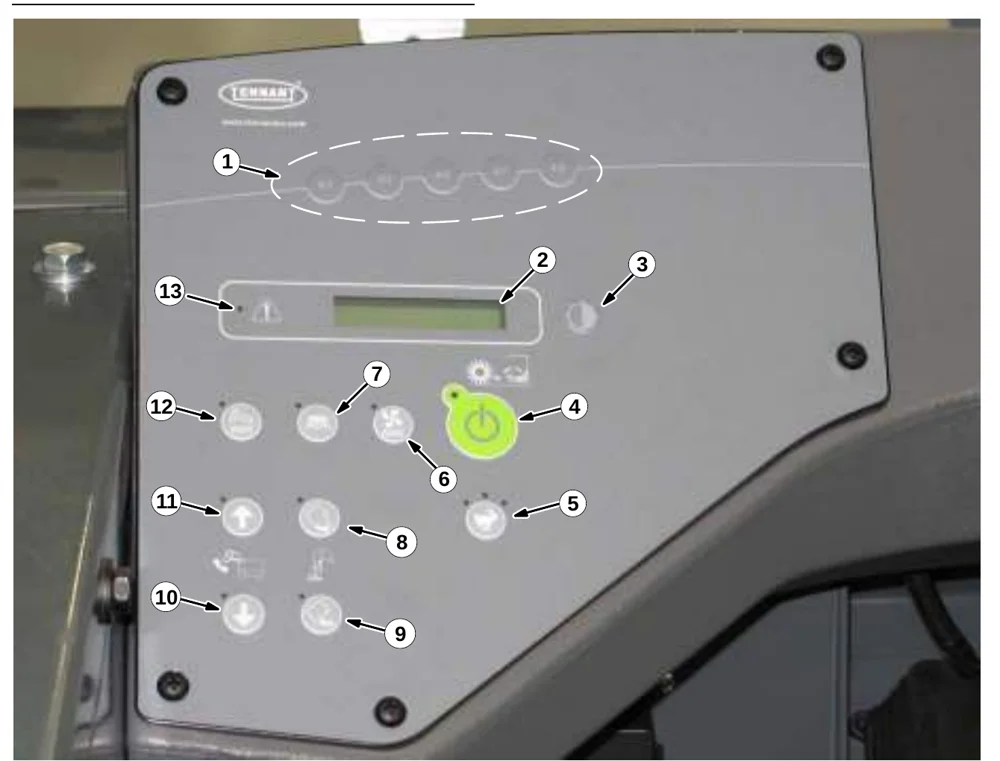
TOUCH PANEL (S30 XP and X4)

In short This page shows the touch panel used on the S30 XP and X4 models and names each of its 13 numbered controls and indicators, such as the sweep, engine speed, vacuum fan, side brush and hopper buttons.‌‌​⁠‍⁠​​⁠⁠‍‌‌‍‍‌⁠‍‌​​​​​​​‍⁠​​​‌​⁠​​‍‌​‌‌​⁠‍​⁠⁠⁠‌‍‍‍‌‍​‌‍‍‍⁠
Photo of the touch panel with callouts 1 to 13: five supervisor buttons in a dashed oval (1), display (2), contrast button (3), green 1-STEP start button (4), engine speed (5), vacuum fan (6), side brush (7), hopper door open (8) and close (9), hopper lower (10) and raise (11), filter shaker (12), and fault indicator light (13)
  1. Supervisor control buttons
  2. Hour meter / fuel indicator / fault code indicator
  3. Contrast control button
  4. 1−STEP sweep button
  5. Engine speed button
  6. Vacuum fan button
  7. Side brush button
  8. Hopper door open button
  9. Hopper door close button
  10. Hopper lower button
  11. Hopper raise button
  12. Filter shaker button
  13. Fault indicator light
Source: Tennant S30 Diesel Operator Manual 9004087 Rev. 09 (4-2015), page 11, used with permission. SES ref PF-7VUQ-EYMQ‌‌​⁠‍⁠​​⁠⁠‍‌‌‍‍‌⁠‍‌​​​​​​​‍⁠​​​‌​⁠​​‍‌​‌‌​⁠‍​⁠⁠⁠‌‍‍‍‌‍​‌‍‍‍⁠
S30 Diesel 9004087 (Rev. 09 (4-2015))Page 11 of 74
OPERATION

OPERATION

SYMBOL DEFINITIONS

In short This page shows the symbols used on the machine to mark controls, displays and features, with the name of each one. Some symbols apply to the S30 and others to the S30 XP and X4.‌‌​⁠‍⁠​​⁠⁠‍‌‌‍‍‌⁠‍‌​​​​​​​⁠​​​​‌​⁠​​⁠‍‌⁠​​​​‌⁠​⁠⁠‍​‌​​​​‍‍‌​

These symbols are used on the machine to identify controls, displays, and features. See also Display Module Fault Indicators (S30) and Dash Fault Indicators.‌‌​⁠‍⁠​​⁠⁠‍‌‌‍‍‌⁠‍‌​​​​​​​⁠​​​​‌​⁠​​⁠‍‌⁠​​​​‌⁠​⁠⁠‍​‌​​​​‍‍‌​

SymbolMeaning
Sweep symbol: a spinning brush next to a hopper with debris
Sweep (S30)
Vacuum fan symbol: a fan with four blades
Vacuum fan (S30)
Filter shaker symbol: a zigzag line next to a hammer
Filter Shaker (S30)
Engine idle speed symbol: a tortoise
Engine Idle Speed (S30)
Engine high speed symbol: a running rabbit
Engine High speed (S30)
Empty hopper symbol: a hopper raised over a machine with debris falling out
Empty Hopper (S30)
Hopper door automatic symbol: a door with arrows
Hopper Door Automatic (S30)
Hopper door manual open symbol: a door with an arrow
Hopper Door Manual Open (S30)
Hopper lower symbol: a downward arrow beside a machine
Hopper Lower (S30)
Hopper raise symbol: an upward arrow beside a machine
Hopper Raise (S30)
Wand symbol: a wand with a floor tool
Wand
Operating lights symbol: a lamp with light rays
Operating lights
Hazard light symbol: a beacon with rays
Hazard light
Horn symbol
Horn
Diesel fuel only symbol: a fuel pump marked D
Diesel fuel only
SymbolMeaning
Jack point symbol: a downward arrow with a jack
Jack point
Fault indicator symbol: an exclamation mark in a triangle
Fault indicator (S30 XP and X4)
Contrast control symbol: a half-shaded circle with rays
Contrast Control (S30 XP and X4)
1-STEP Sweep symbol: a spinning brush next to a hopper with debris
1−STEP Sweep (S30 XP and X4)
Engine speed symbol: a running rabbit in a circle
Engine speed (S30 XP and X4)
Vacuum fan symbol in a circle with a zigzag line
Vacuum fan (S30 XP and X4)
Side brush symbol in a circle
Side brush (S30 XP and X4)
Filter shaker symbol in a circle: a hammer and zigzag line
Filter shaker (S30 XP and X4)
Hopper up/down symbol: two-way arrows beside a machine
Hopper Up / Down (S30 XP and X4)
Hopper raise symbol: an upward arrow in a circle
Hopper raise (S30 XP and X4)
Hopper lower symbol: a downward arrow in a circle
Hopper lower (S30 XP and X4)
Open/Close hopper door symbol: a hopper with a door and debris
Open/Close Hopper Door (S30 XP, X4)
Hopper door open symbol in a circle
Hopper door open (S30 XP and X4)
Hopper door close symbol in a circle
Hopper door close (S30 XP and X4)
Source: Tennant S30 Diesel Operator Manual 9004087 Rev. 09 (4-2015), page 12, used with permission. SES ref PF-GOKM-NEDE‌‌​⁠‍⁠​​⁠⁠‍‌‌‍‍‌⁠‍‌​​​​​​​⁠​​​​‌​⁠​​⁠‍‌⁠​​​​‌⁠​⁠⁠‍​‌​​​​‍‍‌​
S30 Diesel 9004087 (Rev. 09 (4-2015))Page 12 of 74
OPERATION

OPERATION OF CONTROLS

In short This section describes the foot pedals the operator uses: the directional pedal moves the machine forward or backward, the brake pedal stops it and sets the parking brake, and the steering column tilt pedal adjusts the column position.‌‌​⁠‍⁠​​⁠⁠‍‌‌‍‍‌⁠‍‌​​​​​​​⁠‌​​​‌​⁠​​‌⁠⁠​​‌​⁠⁠⁠​​⁠⁠‍⁠​​⁠‌‍‍​⁠

DIRECTIONAL PEDAL

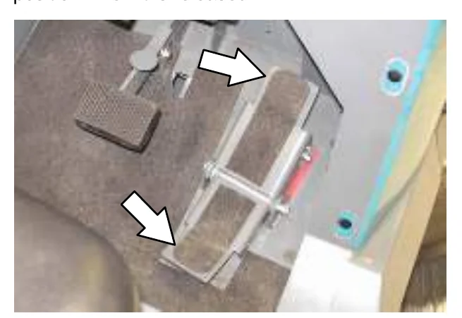
Press the top of the Directional pedal to move forward and the bottom of the pedal to move backward. The pedal returns to the neutral position when it is released.‌‌​⁠‍⁠​​⁠⁠‍‌‌‍‍‌⁠‍‌​​​​​​​⁠‌​​​‌​⁠​​‌⁠⁠​​‌​⁠⁠⁠​​⁠⁠‍⁠​​⁠‌‍‍​⁠

Photo of the directional pedal beside the brake pedal, with two arrows pointing to the top and the bottom of the directional pedal

BRAKE PEDAL

Press the Brake pedal to stop the machine.
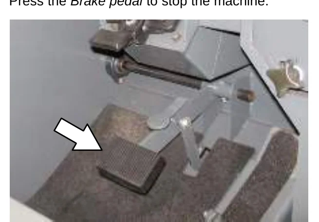
Photo of the brake pedal with an arrow pointing to it

PARKING BRAKE PEDAL

Press the Brake pedal down as far as possible and use toe to lock the Parking brake pedal into place. Press the Brake pedal to release the parking brake. The Parking brake pedal will return to the unlocked position.
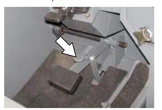
Photo of the parking brake pedal with an arrow pointing to it, above the brake pedal

STEERING COLUMN TILT PEDAL

  1. Step on the Steering column tilt pedal and adjust the steering column to the desired position.
  2. Release the Steering column tilt pedal to lock in place.
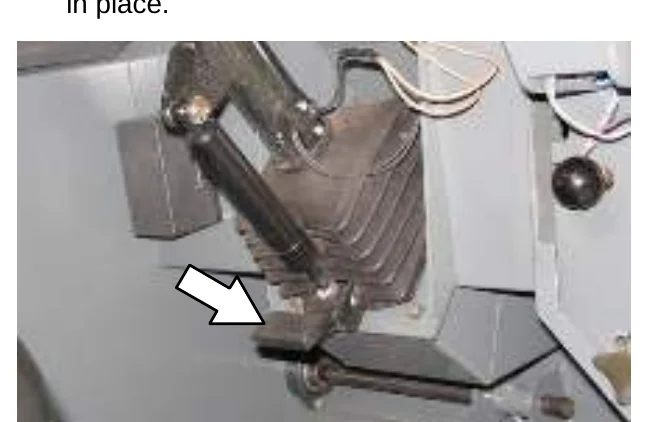
Photo of the steering column tilt pedal below the steering column with an arrow pointing to it
Source: Tennant S30 Diesel Operator Manual 9004087 Rev. 09 (4-2015), page 13, used with permission. SES ref PF-EASB-AAXS‌‌​⁠‍⁠​​⁠⁠‍‌‌‍‍‌⁠‍‌​​​​​​​⁠‌​​​‌​⁠​​‌⁠⁠​​‌​⁠⁠⁠​​⁠⁠‍⁠​​⁠‌‍‍​⁠
S30 Diesel 9004087 (Rev. 09 (4-2015))Page 13 of 74
OPERATION

OPERATION

FUEL GAUGE

In short This section explains that the fuel indicator on the display shows how much fuel is left in the tank. A fuel level fault indicator lights when the tank is nearly empty.‌‌​⁠‍⁠​​⁠⁠‍‌‌‍‍‌⁠‍‌​​​​​​​⁠‍​​​‌​⁠​​‌‌‌⁠‍⁠​⁠​​⁠‌​‌‍​‌‌‌​⁠⁠‍‍

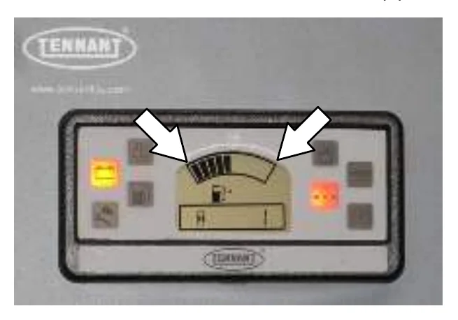
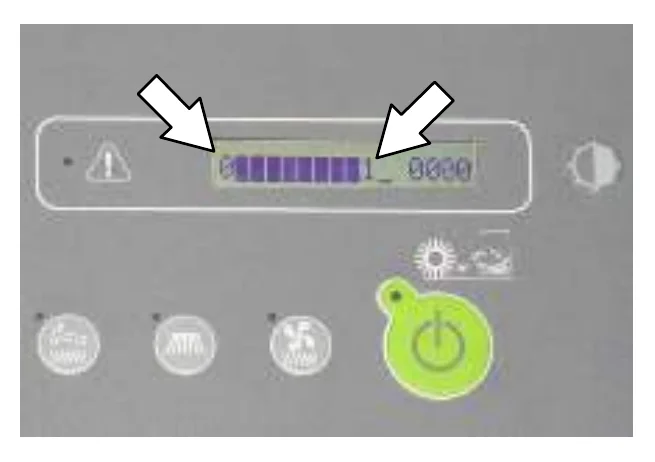
The Fuel indicator displays the amount of fuel left in the tank. The fuel level fault indicator will illuminate when the fuel tank is near empty. Refer to DISPLAY MODULE FAULT INDICATOR(S).‌‌​⁠‍⁠​​⁠⁠‍‌‌‍‍‌⁠‍‌​​​​​​​⁠‍​​​‌​⁠​​‌‌‌⁠‍⁠​⁠​​⁠‌​‌‍​‌‌‌​⁠⁠‍‍

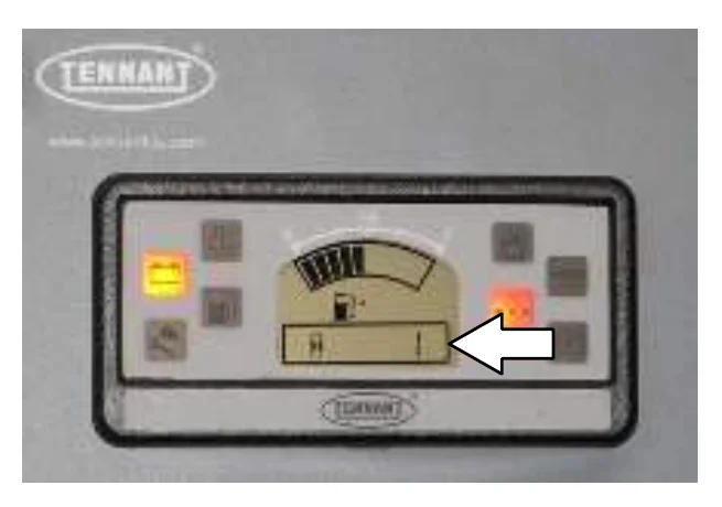
Photo of the S30 display panel with two arrows pointing to the curved fuel gauge bar segments at the top of the display
S30
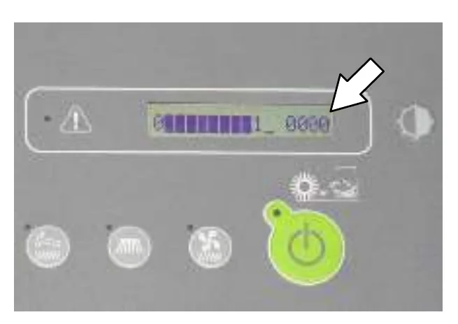
Photo of the S30 XP and X4 control panel with two arrows pointing to the left and right ends of the bar-graph fuel indicator on the display
S30 XP and X4
Source: Tennant S30 Diesel Operator Manual 9004087 Rev. 09 (4-2015), page 14, used with permission. SES ref PF-P57J-IY7L‌‌​⁠‍⁠​​⁠⁠‍‌‌‍‍‌⁠‍‌​​​​​​​⁠‍​​​‌​⁠​​‌‌‌⁠‍⁠​⁠​​⁠‌​‌‍​‌‌‌​⁠⁠‍‍
S30 Diesel 9004087 (Rev. 09 (4-2015))Page 14 of 74
OPERATION

OPERATION

HOUR METER

In short The hour meter records how many hours the machine has been operated, and that figure is used to decide machine service intervals.‌‌​⁠‍⁠​​⁠⁠‍‌‌‍‍‌⁠‍‌​​​​​​​⁠⁠​​​‌​⁠​​⁠‌‌​‌‍​‍​‌‍⁠⁠‍‌‌​⁠​⁠‌‍‌⁠

The Hour meter records the hours the machine was operated. Use this information to determine machine service intervals.‌‌​⁠‍⁠​​⁠⁠‍‌‌‍‍‌⁠‍‌​​​​​​​⁠⁠​​​‌​⁠​​⁠‌‌​‌‍​‍​‌‍⁠⁠‍‌‌​⁠​⁠‌‍‌⁠

S30 instrument panel with the hour meter display on the lower part of the gauge cluster, with an arrow pointing to it
S30
S30 XP and X4 panel with a digital display showing hours, with an arrow pointing at the display, and the green start button below
S30 XP and X4

SUPERVISOR CONTROL BUTTONS (S30 XP and X4)

The Supervisor Control buttons are for accessing the configuration and diagnostic modes. Only properly trained service personnel and TENNANT representatives should access these modes.
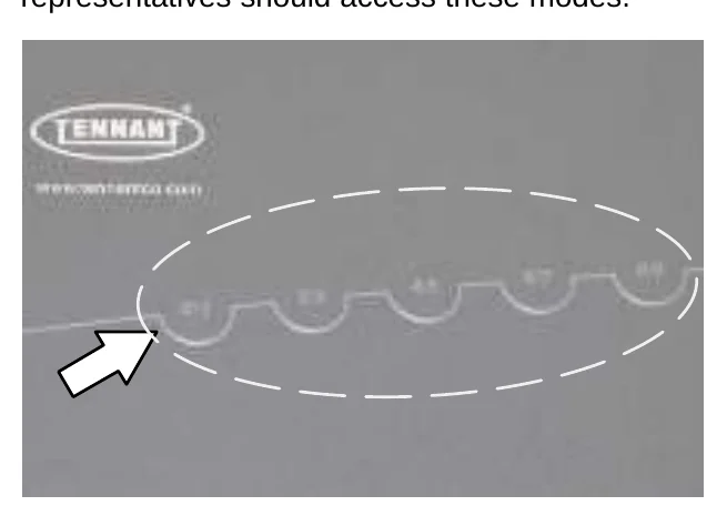
Supervisor control buttons row below the Tennant logo, circled by a dashed oval, with an arrow pointing at the buttons

ENGINE SPEED CONTROLS

In short The engine runs at three speeds: idle for starting, medium (Fast 1) for general sweeping, and high (Fast 2) for sweeping light litter or moving quickly between areas. Photos show the switch and indicator positions on the S30 and on the S30 XP and X4.

Idle Speed: This speed is for starting the machine.
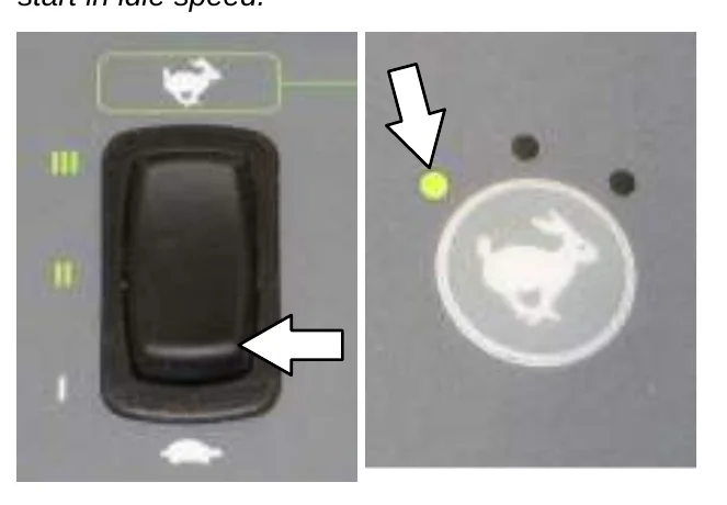
NOTE: S30 XP and X4 machines automatically start in idle speed.
Idle speed: S30 rocker switch in the low position with an arrow, beside the S30 XP and X4 hare button with the left indicator light lit and an arrow
S30 / S30 XP and X4

Medium (Fast 1) Speed: This speed is for general sweeping.
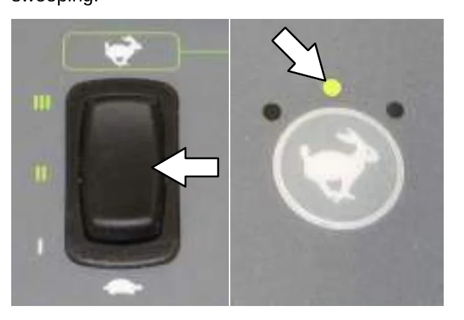
Medium (Fast 1) speed: S30 rocker switch in the middle position with an arrow, beside the S30 XP and X4 hare button with the center indicator light lit and an arrow
S30 / S30 XP and X4

High (Fast 2) Speed: This speed is for sweeping light litter or moving quickly between areas.
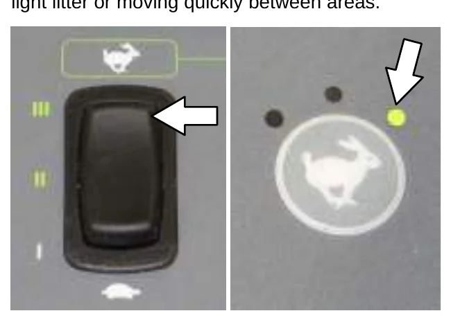
High (Fast 2) speed: S30 rocker switch in the top position with an arrow, beside the S30 XP and X4 hare button with the right indicator light lit and an arrow
S30 / S30 XP and X4
Source: Tennant S30 Diesel Operator Manual 9004087 Rev. 09 (4-2015), page 15, used with permission. SES ref PF-GNS6-UOHK‌‌​⁠‍⁠​​⁠⁠‍‌‌‍‍‌⁠‍‌​​​​​​​⁠⁠​​​‌​⁠​​⁠‌‌​‌‍​‍​‌‍⁠⁠‍‌‌​⁠​⁠‌‍‌⁠
S30 Diesel 9004087 (Rev. 09 (4-2015))Page 15 of 74
OPERATION

VACUUM FAN CONTROLS (S30)

In short On the S30 the vacuum fan starts by itself when the main brush is lowered and the Vacuum fan switch is in the automatic/on position. Move the switch to the middle position to shut it off, for example when sweeping wet areas.‌‌​⁠‍⁠​​⁠⁠‍‌‌‍‍‌⁠‍‌​​​​​​‌​​​​​‌​⁠​​​​‌‌‍‌⁠⁠‌⁠‍⁠⁠⁠‍​⁠‍‍‌‌‌​​

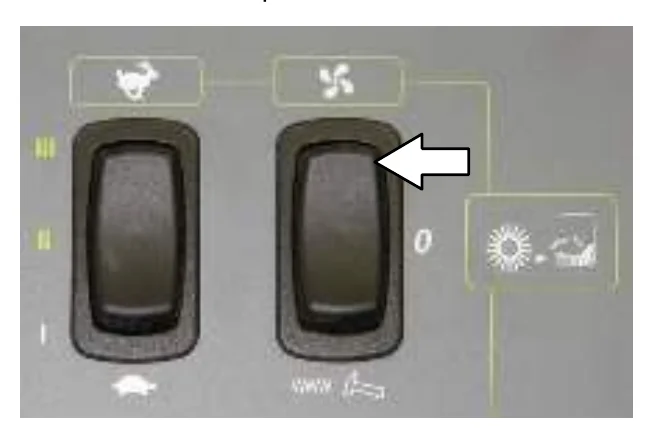
The vacuum fan automatically comes on when the main brush is lowered with the Vacuum fan switch in the automatic/on position.‌‌​⁠‍⁠​​⁠⁠‍‌‌‍‍‌⁠‍‌​​​​​​‌​​​​​‌​⁠​​​​‌‌‍‌⁠⁠‌⁠‍⁠⁠⁠‍​⁠‍‍‌‌‌​​

S30 control panel with two black rocker switches; a white arrow points to the right-hand Vacuum fan switch, which is in the automatic/on position
NOTE: Turn off the vacuum fan when sweeping over large wet areas or standing water. This prevents the dust filter from getting wet while sweeping.

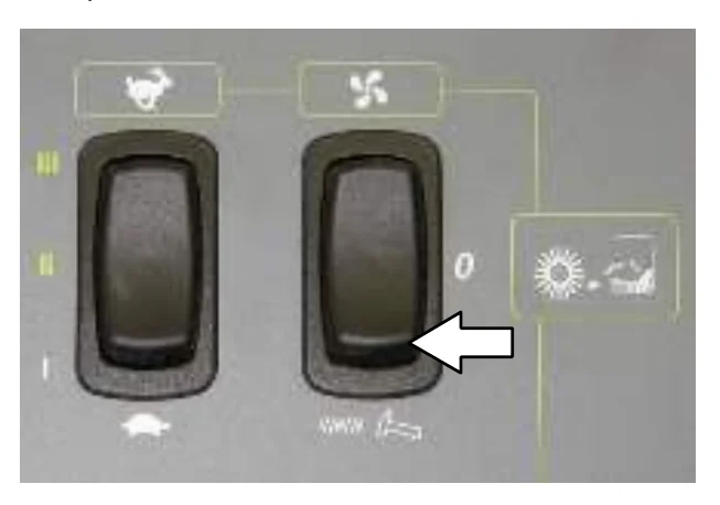
Press the Vacuum fan switch to the middle position to shut off the vacuum fan.
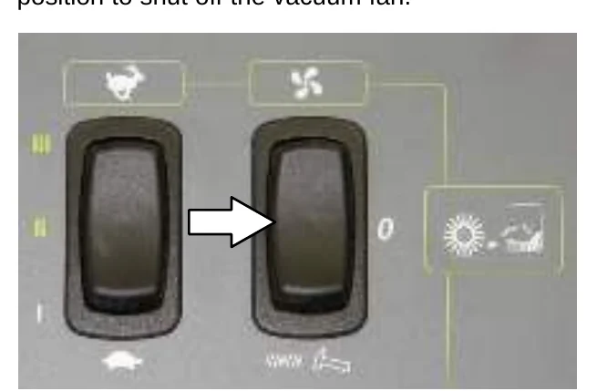
S30 control panel with the two rocker switches; a white arrow points to the Vacuum fan switch pressed to the middle position to shut off the vacuum fan

VACUUM FAN CONTROLS (S30 XP and X4)

In short On the S30 XP and X4 the vacuum fan comes on when the 1-STEP Sweep button is activated, and a light next to the Vacuum fan button comes on. Press the Vacuum fan button to turn it off; the light goes out. The same section also covers the Contrast control button, which darkens or lightens the LCD display.

The vacuum fan automatically comes on when the 1−STEP Sweep button is activated. The light next to the Vacuum fan button will come on.
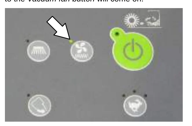
S30 XP and X4 control panel with round buttons and a green power button; an arrow points to the light next to the Vacuum fan button, which is lit
NOTE: Turn off the vacuum fan when sweeping over large wet areas or standing water. This prevents the dust filter from getting wet while sweeping.

Press the Vacuum fan button to shut off the vacuum fan. The light next to the button will go out.
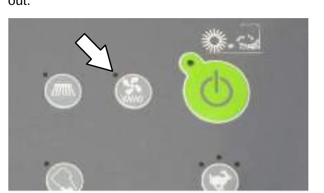
S30 XP and X4 control panel; an arrow points to the Vacuum fan button with its light out after the fan is shut off

CONTRAST CONTROL BUTTON (S30 XP and X4)

Press and hold the Contrast control button to darken/lighten the LCD display.
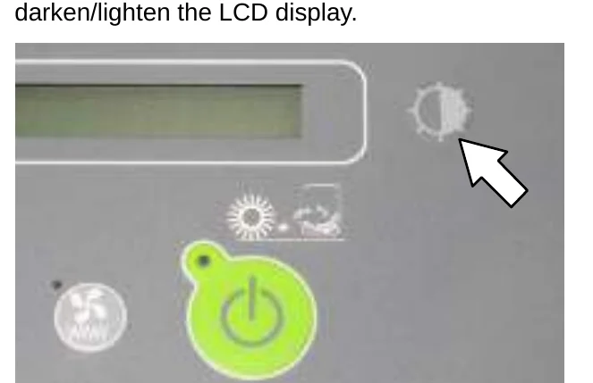
S30 XP and X4 panel showing the LCD display and the Contrast control button at its upper right, marked by an arrow
Source: Tennant S30 Diesel Operator Manual 9004087 Rev. 09 (4-2015), page 16, used with permission. SES ref PF-X6JD-MSA5‌‌​⁠‍⁠​​⁠⁠‍‌‌‍‍‌⁠‍‌​​​​​​‌​​​​​‌​⁠​​​​‌‌‍‌⁠⁠‌⁠‍⁠⁠⁠‍​⁠‍‍‌‌‌​​
S30 Diesel 9004087 (Rev. 09 (4-2015))Page 16 of 74
OPERATION

FILTER SHAKER CONTROL (S30)

In short This section covers the filter shaker switch on the S30. Pressing it runs the filter shaker for 30 seconds.‌‌​⁠‍⁠​​⁠⁠‍‌‌‍‍‌⁠‍‌​​​​​​‌​‌​​​‌​⁠​​⁠​⁠​⁠​⁠‌‍‌‍​​⁠​‌‌​⁠​​‍​​

Press the Filter shaker switch. The filter shaker will operate for 30 seconds.‌‌​⁠‍⁠​​⁠⁠‍‌‌‍‍‌⁠‍‌​​​​​​‌​‌​​​‌​⁠​​⁠​⁠​⁠​⁠‌‍‌‍​​⁠​‌‌​⁠​​‍​​

Close-up of the S30 switch panel with two rocker switches; a white arrow points at the lower part of the right-hand rocker, the filter shaker switch

FILTER SHAKER CONTROL (S30 XP and X4)

In short On the S30 XP and X4 the filter shaker starts by itself when the 1−STEP Sweep button is turned off. You can also press the filter shaker switch to start or stop the 30 second cycle by hand.

The filter shaker automatically activates for about 30 seconds when the 1−STEP Sweep button is turned off.

Press the filter shaker switch to manually start the 30 second shaker cycle or to stop the shaker cycle.
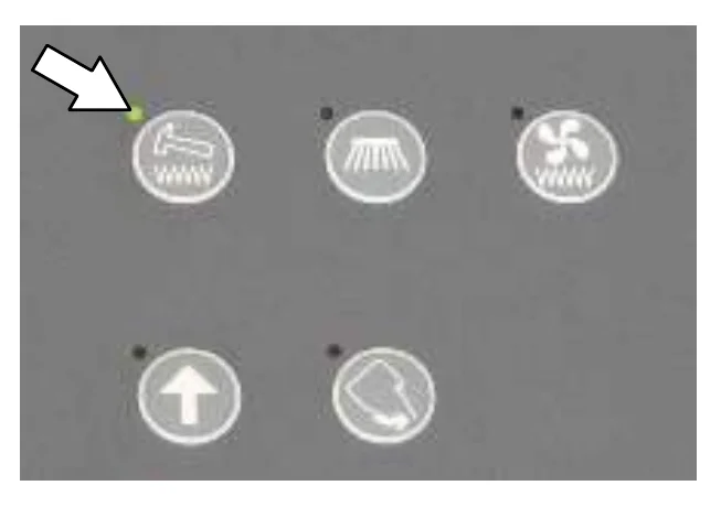
Button panel for the S30 XP and X4 with five round buttons; a white arrow points at the top-left filter shaker button, which has a green indicator light

OPERATING / HAZARD LIGHT SWITCH

In short The operating / hazard light switch has three positions. Top turns on operating and hazard lights, middle turns on operating lights only, and bottom turns all lights off.

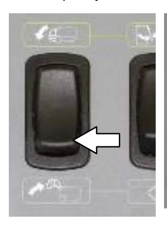
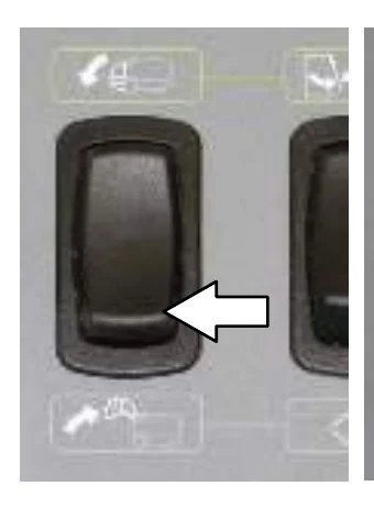
Operating and Hazard Lights On: Press the top of the Operating / hazard light switch.

Operating Lights On: Press the Operating / hazard light switch to the middle position.

All Lights Off: Press the bottom of the Operating / hazard light switch.
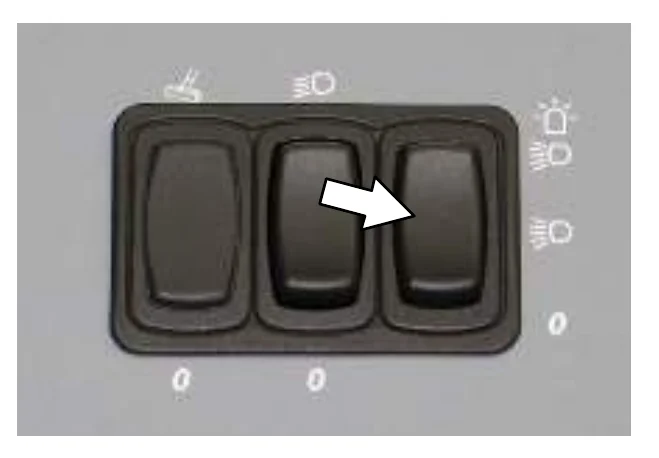
Three-rocker light switch panel; a white arrow points at the top of the right-hand operating / hazard light switch

SIDE BRUSH LIGHT SWITCH (OPTION)

In short The optional side brush light switch turns the side brush light on at the top position and off at the bottom position.

Side Brush Lights On: Press the top of the Side brush light switch to turn the side brush light on.

Side Brush Lights Off: Press the bottom of the Side brush light switch to turn the side brush light off.
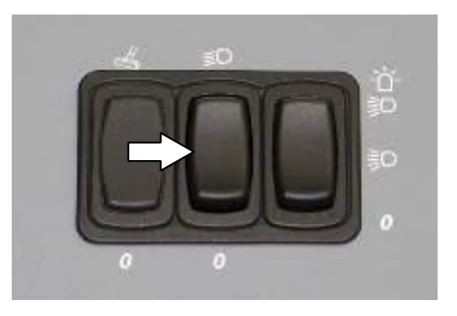
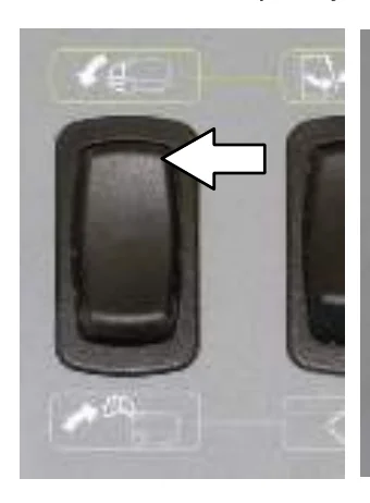
Three-rocker light switch panel; a white arrow points at the middle rocker, the side brush light switch
Source: Tennant S30 Diesel Operator Manual 9004087 Rev. 09 (4-2015), page 17, used with permission. SES ref PF-LRUX-JYBK‌‌​⁠‍⁠​​⁠⁠‍‌‌‍‍‌⁠‍‌​​​​​​‌​‌​​​‌​⁠​​⁠​⁠​⁠​⁠‌‍‌‍​​⁠​‌‌​⁠​​‍​​
S30 Diesel 9004087 (Rev. 09 (4-2015))Page 17 of 74
OPERATION

OPERATION

HOPPER ACCESS DOOR

In short The hopper access door is used to get rid of debris too large for the machine to pick up while sweeping. How you open it depends on the machine serial number: twist and lift the handle on earlier machines, or simply pull the handle on later ones.‌‌​⁠‍⁠​​⁠⁠‍‌‌‍‍‌⁠‍‌​​​​​​‌​‍​​​‌​⁠​​⁠⁠⁠​⁠​‌‌‍‍‌⁠​​‌‌​⁠⁠⁠⁠‌​‍

Use the hopper access door to dispose of debris too large to be picked up by the machine while sweeping.‌‌​⁠‍⁠​​⁠⁠‍‌‌‍‍‌⁠‍‌​​​​​​‌​‍​​​‌​⁠​​⁠⁠⁠​⁠​‌‌‍‍‌⁠​​‌‌​⁠⁠⁠⁠‌​‍

Twist the hopper access door handle to loosen the lock, lift the handle to disengage the lock, and then lift the hopper access door open.
(SN 000000 − 006500)
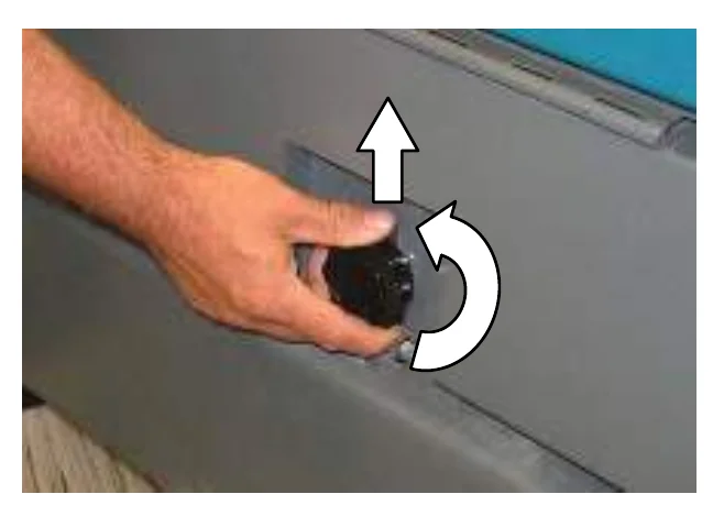
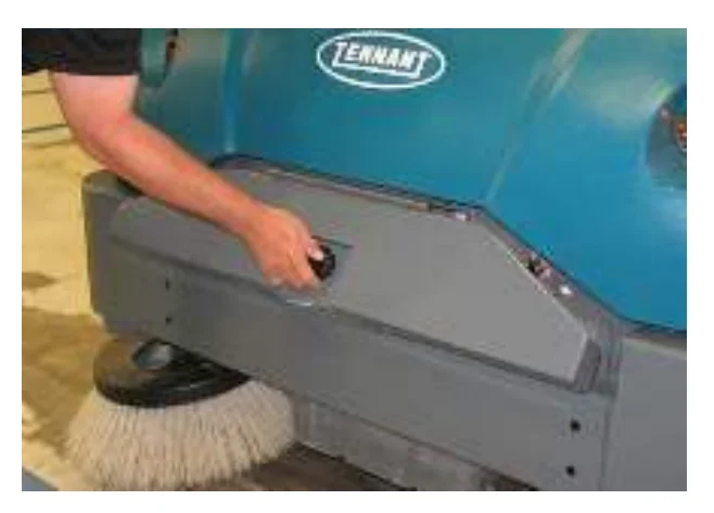
Close-up of a hand gripping the round hopper access door handle on the gray side panel, with a white arrow pointing up and a curved white arrow showing the twisting direction
Operator bending beside the machine lifting the hopper access door by its handle on the gray side panel, with the side brush visible below

Pull the hopper access door handle to open the hopper access door. (SN 006501 − )
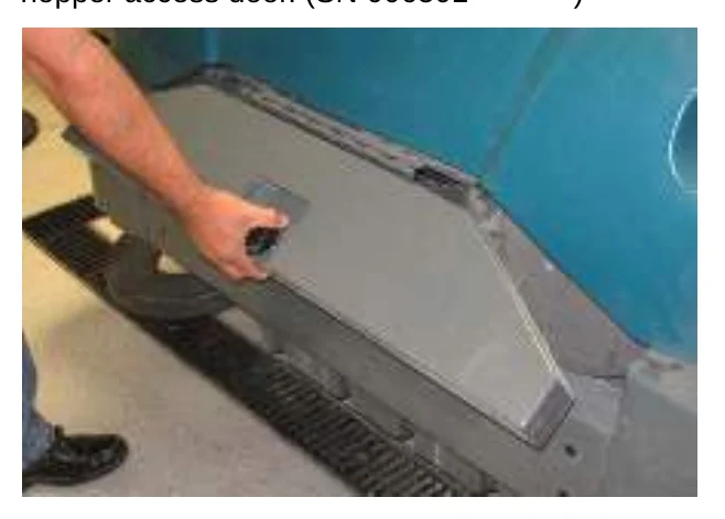
Operator pulling the hopper access door handle outward to open the door on the side of the machine
Source: Tennant S30 Diesel Operator Manual 9004087 Rev. 09 (4-2015), page 18, used with permission. SES ref PF-B7ZD-5SP6‌‌​⁠‍⁠​​⁠⁠‍‌‌‍‍‌⁠‍‌​​​​​​‌​‍​​​‌​⁠​​⁠⁠⁠​⁠​‌‌‍‍‌⁠​​‌‌​⁠⁠⁠⁠‌​‍
S30 Diesel 9004087 (Rev. 09 (4-2015))Page 18 of 74
OPERATION

OPERATOR SEAT

In short This page shows how to adjust the operator seat and the deluxe suspension seat: seat position, backrest angle and weight setting. Adjust the seat and fasten the seat belt (if equipped) before starting the machine.‌‌​⁠‍⁠​​⁠⁠‍‌‌‍‍‌⁠‍‌​​​​​​‌​⁠​​​‌​⁠​​‍​‍‌​‍‌⁠‌‌⁠⁠‍‍​‌‍⁠⁠‍‍‍‌⁠

The front−to−back adjustment lever adjusts the seat position.‌‌​⁠‍⁠​​⁠⁠‍‌‌‍‍‌⁠‍‌​​​​​​‌​⁠​​​‌​⁠​​‍​‍‌​‍‌⁠‌‌⁠⁠‍‍​‌‍⁠⁠‍‍‍‌⁠

Standard black operator seat with an arrow pointing to the front-to-back adjustment lever under the front of the seat

DELUXE SUSPENSION SEAT

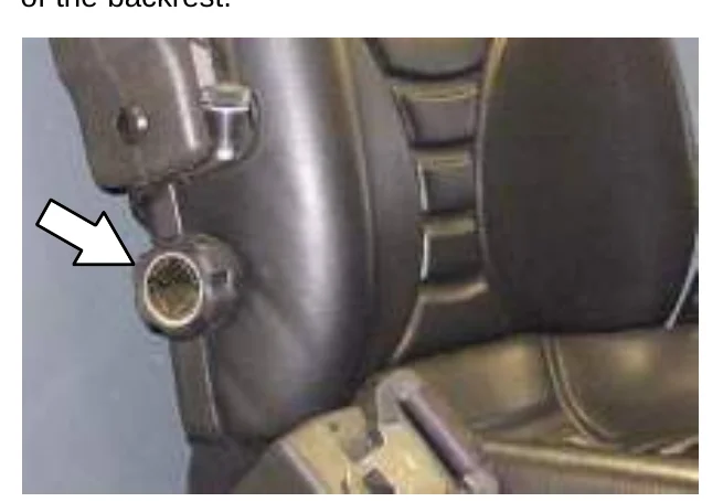
The operator seat has three adjustments: backrest angle, operator weight, and front to back.

The backrest adjustment knob adjusts the angle of the backrest.

Side of the deluxe suspension seat backrest with an arrow pointing to the backrest angle adjustment knob

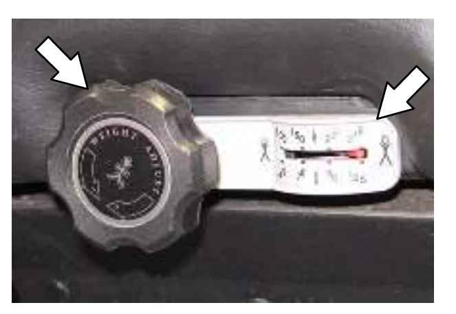
The weight adjustment knob controls the firmness of the operator seat. Use the gauge next to the weight adjustment knob to help determine seat firmness.

Weight adjustment knob and the gauge beside it on the deluxe seat, with arrows pointing to the knob and to the gauge

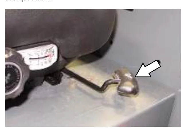
The front−to−back adjustment lever adjusts the seat position.
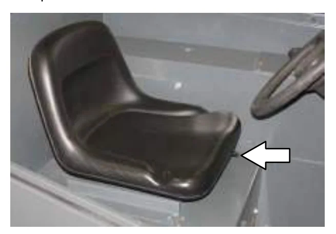
Deluxe seat front-to-back adjustment lever under the seat with an arrow pointing to it

SEAT BELTS

FOR SAFETY: Before starting machine, adjust seat and fasten seat belt (if equipped).
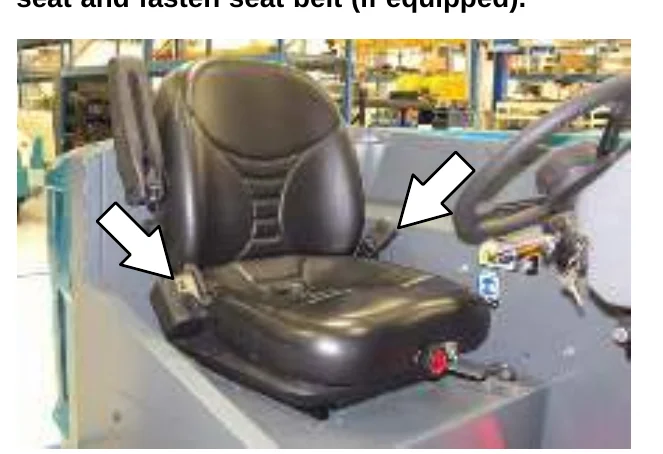
Deluxe seat on the machine with arrows pointing to the seat belt buckle and the seat belt on either side of the seat
Source: Tennant S30 Diesel Operator Manual 9004087 Rev. 09 (4-2015), page 19, used with permission. SES ref PF-AS5E-W45A‌‌​⁠‍⁠​​⁠⁠‍‌‌‍‍‌⁠‍‌​​​​​​‌​⁠​​​‌​⁠​​‍​‍‌​‍‌⁠‌‌⁠⁠‍‍​‌‍⁠⁠‍‍‍‌⁠
S30 Diesel 9004087 (Rev. 09 (4-2015))Page 19 of 74
OPERATION

BRUSH INFORMATION

In short This section lists the main and side brush types and what each one is recommended for, so you can match the brush to the cleaning job. Contact a Tennant representative for specific recommendations.‌‌​⁠‍⁠​​⁠⁠‍‌‌‍‍‌⁠‍‌​​​​​​‌‌​​​​‌​⁠​​⁠‌‍‌⁠‌⁠‌​⁠‍​‌​‌‍‍‍‌​‌‍‌⁠

For best results, use the correct brush type for the cleaning application.‌‌​⁠‍⁠​​⁠⁠‍‌‌‍‍‌⁠‍‌​​​​​​‌‌​​​​‌​⁠​​⁠‌‍‌⁠‌⁠‌​⁠‍​‌​‌‍‍‍‌​‌‍‌⁠

NOTE: The amount and type of soilage play an important role in determining the type of brushes to use. Contact a Tennant representative for specific recommendations.

Polypropylene and Wire 8-double row Main Brush − Recommended for general sweeping, fine dust, and slightly impacted debris.

Polypropylene Sand Wedge Main Brush − Recommended for heavy accumulation of sand and other small particulates.

Polypropylene Window Main Brush − Recommended for light litter, especially on smooth floors.

Polypropylene 8-double row Main Brush − Recommended for lighter duty sweeping applications.

Nylon 8-double row Main Brush − Recommended for general sweeping, especially on rough or irregular surfaces. Nylon has a long wear life.

Nylon Full Fill Main Brush − Recommended for accumulation of sand and other small particulates. Nylon has a long wear life.

Nylon Patrol Main Brush − Recommended for bulky debris swept at faster speeds.

Wire 8-double row Main Brush − Recommended for general sweeping and slightly impacted debris.

Natural Fiber and Full Fill Main Brush − Recommended for accumulation of sand and other small particulates.

Polypropylene Side Brush − Recommended for general sweeping of light to medium debris.

Nylon Side Brush − Recommended for general sweeping of rough or irregular surfaces. Nylon has a long wear life.

Flat Wire Side Brush − Recommended for outdoor curb-side sweeping where dirt is heavy or compacted.

HOW THE MACHINE WORKS
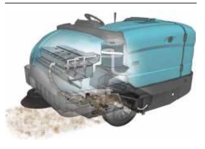
In short This section explains which controls steer, drive and stop the machine and how debris moves from the side brush to the main brush and into the hopper. When sweeping is finished, shake the dust filter and empty the hopper.
Cutaway view of the sweeper for machines SN 000000 to 006500, showing the internal components and debris being swept from the floor into the machine
Machines SN 000000 − 006500

Machines SN 000000 − 006500

Cutaway view of the sweeper for machines SN 006501 and up, showing the engine, the side brush and main brush, and debris on the floor
Machines SN 006501 −

Machines SN 006501 −

The steering wheel controls the direction of machine travel. The directional pedal controls the speed and forward/reverse direction. The brake pedal slows and stops the machine.

The side brush sweeps debris into the path of the main brush. The main brush sweeps debris from the floor into the hopper. The vacuum system pulls dust and air through the hopper and the dust control system.

When sweeping is finished, shake the dust filter and empty the hopper.

Source: Tennant S30 Diesel Operator Manual 9004087 Rev. 09 (4-2015), page 20, used with permission. SES ref PF-4VVP-QXNB‌‌​⁠‍⁠​​⁠⁠‍‌‌‍‍‌⁠‍‌​​​​​​‌‌​​​​‌​⁠​​⁠‌‍‌⁠‌⁠‌​⁠‍​‌​‌‍‍‍‌​‌‍‌⁠
S30 Diesel 9004087 (Rev. 09 (4-2015))Page 20 of 74
OPERATION

PRE−OPERATION CHECKLIST

In short This checklist lists the checks to make before using the machine: fluid levels, brushes, skirts and seals, cooling fins, lights, horn, brakes and steering, and the service records.‌‌​⁠‍⁠​​⁠⁠‍‌‌‍‍‌⁠‍‌​​​​​​‌‌‌​​​‌​⁠​​⁠​​​​⁠​‍‌⁠‍⁠‍⁠⁠‍‍‌‍‌‍​​‍
  • Check the fuel level.
  • Check the machine for fluid leaks.
  • Check the condition of the main brushes. Remove string, banding, plastic wrap, or other debris wrapped around the brushes.
  • Check the main brush compartment right skirts and seals for damage and wear.
  • Side Brush(es): Check the condition of the brush. Remove string, banding, plastic wrap, or other debris wrapped around the brush.
  • Check the condition of the debris deflection skirts.
  • Check the hydraulic fluid level.
  • Check the main brush compartment left skirts and seals for damage and wear.
  • Check the engine coolant level.
  • Check the engine oil level.
  • Check the radiator and hydraulic cooler fins for debris.
  • Check the horn, headlights, taillights, safety lights, and backup alarm (if equipped).
  • Check the brakes and steering for proper operation.
  • Check the service records to determine maintenance requirements.
Source: Tennant S30 Diesel Operator Manual 9004087 Rev. 09 (4-2015), page 21, used with permission. SES ref PF-GQLW-QDK2‌‌​⁠‍⁠​​⁠⁠‍‌‌‍‍‌⁠‍‌​​​​​​‌‌‌​​​‌​⁠​​⁠​​​​⁠​‍‌⁠‍⁠‍⁠⁠‍‍‌‍‌‍​​‍
S30 Diesel 9004087 (Rev. 09 (4-2015))Page 21 of 74
OPERATION

STARTING THE MACHINE

In short This section covers starting the diesel machine: sit in the seat with the brake on, set the engine speed, let the glow plug light come on, then turn the key to start. It also covers warming up the engine and turning the machine off.‌‌​⁠‍⁠​​⁠⁠‍‌‌‍‍‌⁠‍‌​​​​​​‌‌‍​​​‌​⁠​​‌‍‍‍‍‌⁠‍‌‍⁠‍​‍⁠​‌‍​‍‌​‌​
  1. Sit in the operator seat and press the brake pedal or set the parking brake.
FOR SAFETY: When starting machine, keep foot on brake and directional pedal in neutral.
  1. S30: Place the Engine speed switch into the idle position.
    S30 XP and X4: The engine will automatically start in the idle speed.
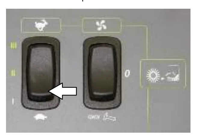
Close-up of the switch panel with two rocker switches; an arrow points to the left rocker, the engine speed switch, at its low idle position marked with a tortoise symbol
  1. Turn the key clockwise until the glow plug light comes on, but not far enough to start the engine. Hold the key in this position for 15 to 30 seconds, depending on temperature. Colder temperatures require longer time.
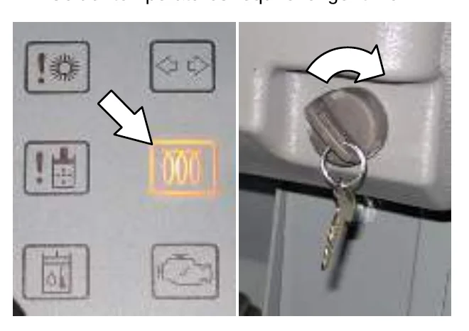
Left: indicator panel with an arrow pointing to the orange glow plug light. Right: ignition switch with the key in it and a curved arrow showing a clockwise turn
  1. Turn the key further clockwise to start the engine.
NOTE: Do not operate the starter motor for more than 10 seconds at a time or after the engine has started. Allow the starter to cool 15−20 seconds between starting attempts or damage to the starter motor may occur.
  1. Allow the engine and hydraulic system to warm up for three to five minutes.
WARNING: Machine emits toxic gases. Severe respiratory damage or asphyxiation can result. Provide adequate ventilation. Consult with your regulatory authorities for exposure limits. Keep engine properly tuned.
  1. Turn on lights.

TURNING OFF THE MACHINE

  1. Stop the machine and turn off all sweeping functions.
  2. Turn the ignition switch key counter clockwise to turn off the machine. Remain in the operator seat until the engine is off.
FOR SAFETY: Before leaving or servicing machine, do not park near combustible materials, dust, gases, or liquids. Stop on level surface, set parking brake, turn off machine, and remove key.
Source: Tennant S30 Diesel Operator Manual 9004087 Rev. 09 (4-2015), page 22, used with permission. SES ref PF-CEX4-7SGR‌‌​⁠‍⁠​​⁠⁠‍‌‌‍‍‌⁠‍‌​​​​​​‌‌‍​​​‌​⁠​​‌‍‍‍‍‌⁠‍‌‍⁠‍​‍⁠​‌‍​‍‌​‌​
S30 Diesel 9004087 (Rev. 09 (4-2015))Page 22 of 74
OPERATION

WHILE OPERATING THE MACHINE

In short This section gives driving and sweeping practices for operating the machine. Pick up oversized debris first, drive slowly on inclines, and stay within the stated temperature and ramp grade limits.‌‌​⁠‍⁠​​⁠⁠‍‌‌‍‍‌⁠‍‌​​​​​​‌‌⁠​​​‌​⁠​​⁠‍‍‌‌‍​‍‍‌⁠⁠‌‍⁠⁠​‌⁠‍⁠‌⁠‌

Pick up oversized debris before sweeping. Pick up wire, string, twine, large pieces of wood, or any other debris that could become wrapped around or tangled in the brushes.‌‌​⁠‍⁠​​⁠⁠‍‌‌‍‍‌⁠‍‌​​​​​​‌‌⁠​​​‌​⁠​​⁠‍‍‌‌‍​‍‍‌⁠⁠‌‍⁠⁠​‌⁠‍⁠‌⁠‌

Drive as straight a path as possible. Avoid bumping into posts or scraping the sides of the machine. Overlap the sweep paths by several centimeters (a few inches).

Avoid turning the steering wheel too sharply when the machine is in motion. The machine is very responsive to the movement of the steering wheel. Avoid sudden turns, except in emergencies.

Adjust the machine speed and brush pressure. Use the lowest brush pressure for best performance.

Keep the machine moving to prevent damaging floor finishes.

If poor cleaning performance is observed, stop cleaning and refer to MACHINE TROUBLESHOOTING in this manual.

Perform the Daily Maintenance Procedures after each use (see MACHINE MAINTENANCE in this manual).

Drive the machine slowly on inclines. Use the brake pedal to control machine speed on descending inclines. Allow more braking distance when traveling at faster speeds. Sweep with the machine up inclines rather than down inclines.

FOR SAFETY: When using machine, go slowly on inclines and slippery surfaces.

Do not operate machine in areas where the ambient temperature is above 43° C (110° F). Do not operate sweeping functions in areas where the ambient temperature is below freezing 0° C (32° F). With the proper hydraulic fluid and a machine warm−up period, the machine is capable of operating at much lower temperatures.

FOR SAFETY: Do not sweep on ramp inclines that exceed 14% grade or transport (GVWR) on ramp inclines that exceed 17% grade.

Source: Tennant S30 Diesel Operator Manual 9004087 Rev. 09 (4-2015), page 23, used with permission. SES ref PF-HKLU-A6HZ‌‌​⁠‍⁠​​⁠⁠‍‌‌‍‍‌⁠‍‌​​​​​​‌‌⁠​​​‌​⁠​​⁠‍‍‌‌‍​‍‍‌⁠⁠‌‍⁠⁠​‌⁠‍⁠‌⁠‌
S30 Diesel 9004087 (Rev. 09 (4-2015))Page 23 of 74
OPERATION

OPERATION

SWEEPING (S30)

In short This section explains how to sweep with the S30. Start the machine, lower the hopper, set the vacuum fan and hopper door switches to automatic, choose an engine speed, lower the brushes, release the parking brake and press the Directional pedal.‌‌​⁠‍⁠​​⁠⁠‍‌‌‍‍‌⁠‍‌​​​​​​‌‍​​​​‌​⁠​​‌⁠​⁠‍‍⁠​​​‍⁠‍‍‍‍‍‌‌‌‌​‍​
FOR SAFETY: Do not operate machine, unless operator manual is read and understood.
  1. Start the machine.
  2. Ensure the hopper is completely lowered.
  3. Ensure the vacuum fan switch is in the automatic/on position.
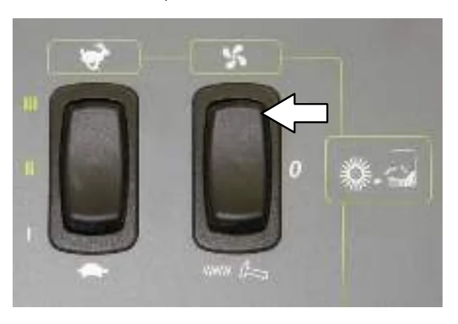
    Switch panel with the engine speed rocker switch on the left and the vacuum fan rocker switch on the right; an arrow points to the upper part of the vacuum fan switch, the automatic/on position
  4. Ensure the hopper door switch is in the upper automatic position.
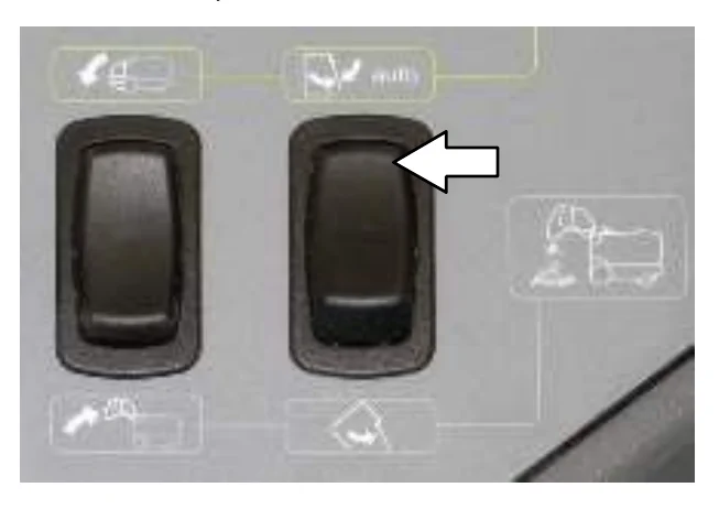
    Switch panel showing the hopper door rocker switch on the right with an arrow pointing to its upper automatic position
  5. Select an engine speed. Use medium speed for general sweeping and high speed for sweeping light litter.
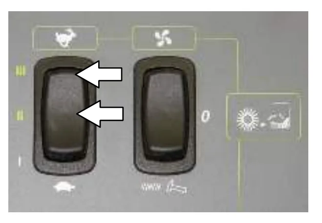
    Engine speed rocker switch on the left with two arrows pointing at its upper positions, medium and high speed, next to the vacuum fan switch
  6. Lower the brushes.
NOTE: The brushes will rotate, the hopper door will open, and the vacuum fan will come on.
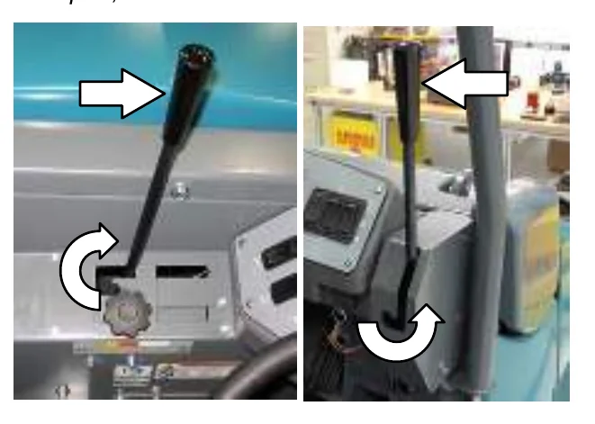
Two photos of the brush lowering lever, with arrows showing the lever being pushed and rotated to lower the brushes
  1. Release the parking brake, then press the Directional pedal to begin sweeping.
FOR SAFETY: When using machine, go slowly on inclines and slippery surfaces.
NOTE: Turn off the vacuum fan when sweeping over large wet areas or standing water. This prevents the dust filter from getting wet while sweeping.
Source: Tennant S30 Diesel Operator Manual 9004087 Rev. 09 (4-2015), page 24, used with permission. SES ref PF-I2AZ-VBRQ‌‌​⁠‍⁠​​⁠⁠‍‌‌‍‍‌⁠‍‌​​​​​​‌‍​​​​‌​⁠​​‌⁠​⁠‍‍⁠​​​‍⁠‍‍‍‍‍‌‌‌‌​‍​
S30 Diesel 9004087 (Rev. 09 (4-2015))Page 24 of 74
OPERATION
  1. To stop sweeping, press the Brake pedal to stop the machine.
  2. Raise the brushes.
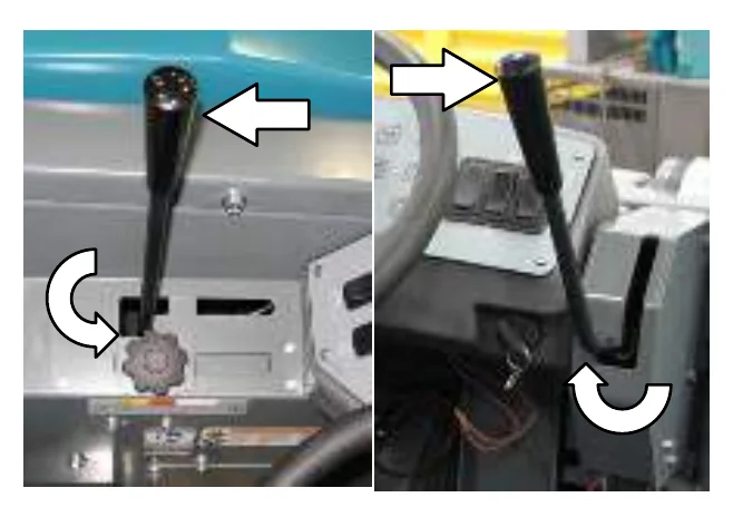
Two photos of the brush lift lever with arrows showing the lever being pushed and rotated to raise the brushes
  1. Press the filter shaker switch to activate the hopper filter shaker. It will operate for about 30 seconds.
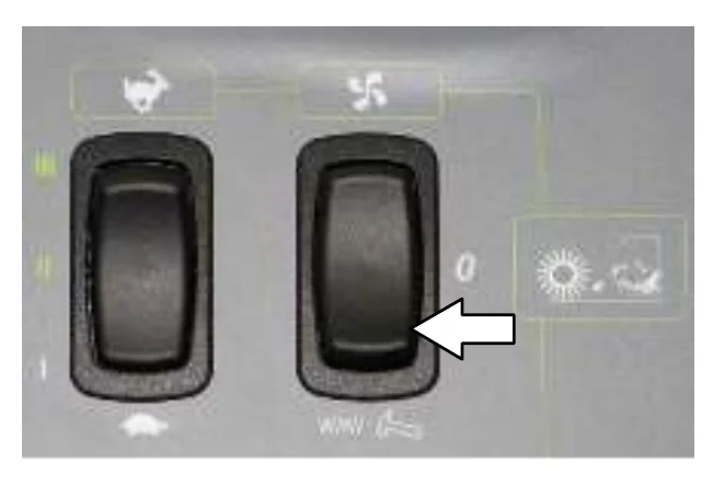
Panel with two rocker switches; an arrow points to the right switch, the filter shaker switch
  1. Empty the debris hopper at the end of each shift or as needed. See EMPTYING THE HOPPER section of this manual.

SWEEPING (S30 XP and X4)

In short This section explains how to sweep with the 1-STEP Sweep button on the S30 XP and X4. Start the machine, press the button to turn on the preset sweeping functions, release the parking brake and press the directional pedal. When finished, stop the machine, press the button again and empty the hopper.‌‌​⁠‍⁠​​⁠⁠‍‌‌‍‍‌⁠‍‌​​​​​​‌‍‌​​​‌​⁠​​​⁠‌‍​​⁠⁠​‍⁠⁠​‍⁠​‍​‌​‍⁠‍‍
FOR SAFETY: Do not operate machine, unless operator manual is read and understood.
  1. Start the machine.
NOTE: Make sure the sweep modes / settings are set before sweeping.
  1. Press the 1−STEP Sweep button. All the preset sweeping functions will turn on. The light on the button will come on.
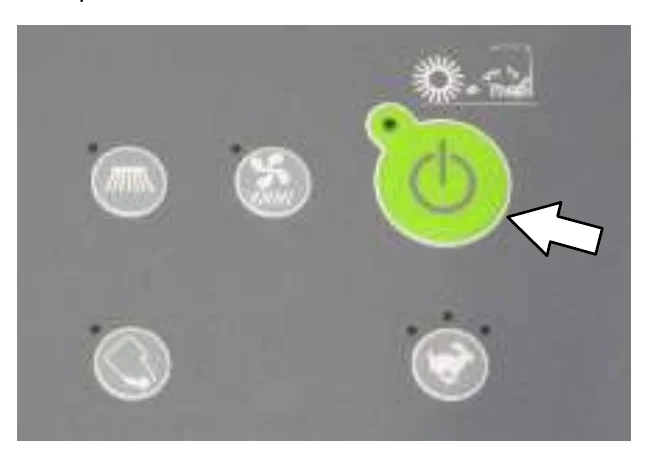
NOTE: The engine idle speed will increase, the brushes will rotate, the hopper door will open, and the vacuum fan will come on. Adjust the engine idle speed as needed.
Control panel with a green 1-STEP Sweep button lit and an arrow pointing to it
  1. Release the parking brake, then press the Directional pedal to begin sweeping.
FOR SAFETY: When using machine, go slowly on inclines and slippery surfaces.
NOTE: Turn off the vacuum fan when sweeping over large wet areas or standing water. This prevents the hopper dust filter from getting wet while sweeping.
  1. To stop sweeping, press the Brake pedal to stop the machine.
  2. Press the 1−STEP Sweep button. The light on the button will turn off. All the preset sweeping functions will turn off and the automatic filter shaker will operate for about 30 seconds.
  3. Empty the debris hopper at the end of each shift or as needed. See EMPTYING THE HOPPER section of this manual.
Source: Tennant S30 Diesel Operator Manual 9004087 Rev. 09 (4-2015), page 25, used with permission. SES ref PF-EZMP-UDXN‌‌​⁠‍⁠​​⁠⁠‍‌‌‍‍‌⁠‍‌​​​​​​‌‍‌​​​‌​⁠​​​⁠‌‍​​⁠⁠​‍⁠⁠​‍⁠​‍​‌​‍⁠‍‍
S30 Diesel 9004087 (Rev. 09 (4-2015))Page 25 of 74
OPERATION

OPERATION

EMPTYING THE HOPPER

In short This section explains how to empty the hopper into a debris container. You drive to the debris site, raise the hopper, open the hopper door to empty it, close the door, then back away.‌‌​⁠‍⁠​​⁠⁠‍‌‌‍‍‌⁠‍‌​​​​​​‌‍‍​​​‌​⁠​​‌‌⁠‍⁠​‌‍‍⁠⁠⁠‍‌​‌​​‍‌‍⁠‍‌
  1. Slowly drive the machine to the debris site or debris container.
  2. Stop the sweeping functions.
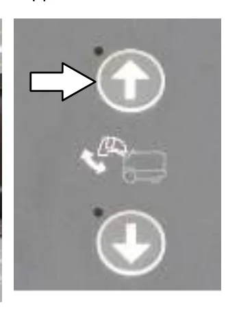
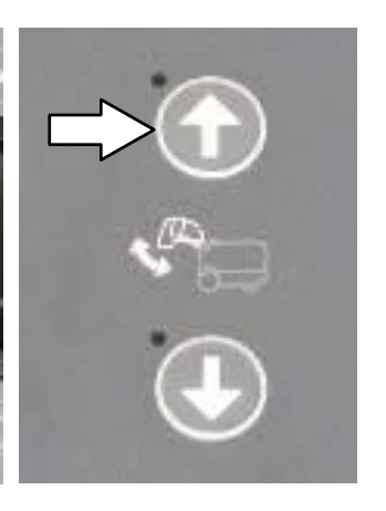
  3. Press and hold the Hopper raise switch or button to raise the hopper.
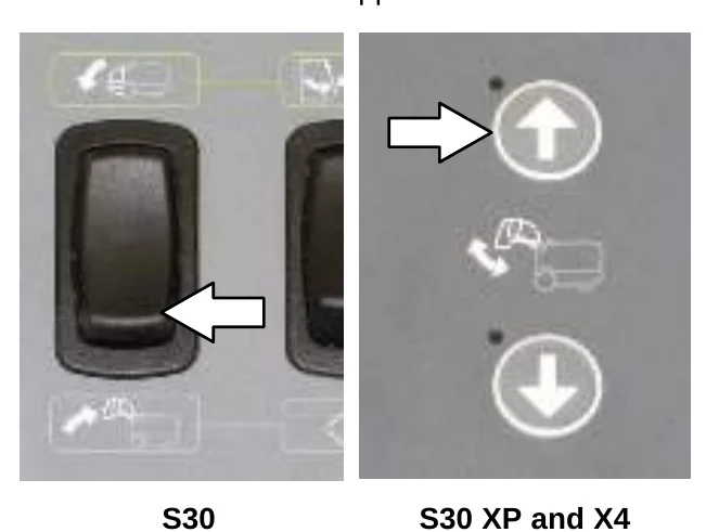
Two photos of the hopper raise control. Left (S30): rocker switch with an arrow pointing to it. Right (S30 XP and X4): panel button with an up arrow icon, hopper icon and down arrow icon, with an arrow pointing at the up button.
S30 / S30 XP and X4
FOR SAFETY: When using machine, make sure adequate clearance is available before raising hopper. Do not raise hopper when machine is on an incline.
NOTE: Be aware the minimum ceiling height needed to raise the hopper is 2500 mm (98 in).
  1. Slowly drive the machine up to the debris container.
FOR SAFETY: When using machine, use care when reversing machine. Move machine with care when hopper is raised.
  1. Lower the hopper into the debris container to control dust.
NOTE: To prevent damaging the machine, DO NOT hit the debris container with the machine.
  1. Open the hopper door to empty the hopper.
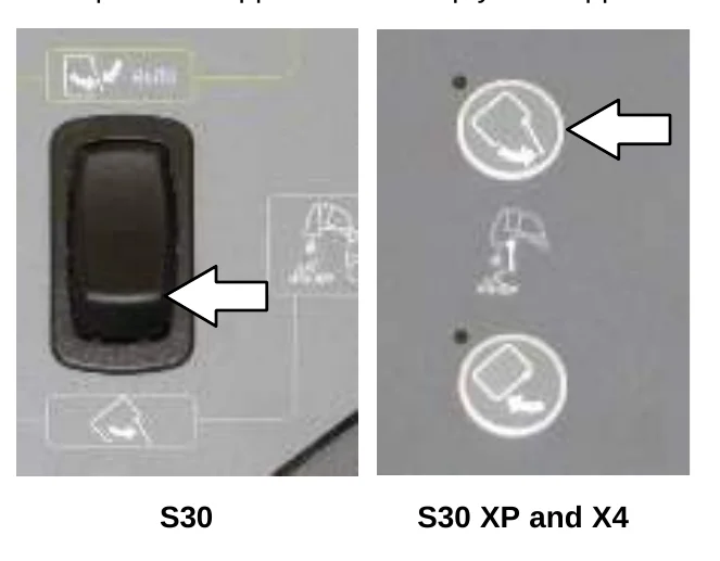
Two photos of the hopper door open control. Left (S30): rocker switch with an arrow pointing to the lower part of the switch. Right (S30 XP and X4): panel with hopper door icons, with an arrow pointing at the upper door open button.
S30 / S30 XP and X4
  1. S30: Place the Hopper door switch in the automatic position to close the hopper door.

    S30 XP and X4: Press the Hopper door close button to close the hopper door.
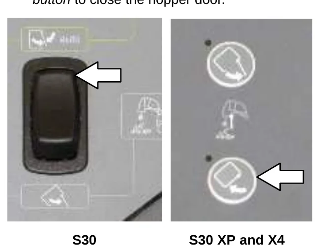
Two photos of the hopper door close control. Left (S30): rocker switch with an arrow pointing to the upper part of the switch. Right (S30 XP and X4): panel with hopper door icons, with an arrow pointing at the lower door close button.
S30 / S30 XP and X4
  1. Raise the hopper enough to clear the top of the debris container.
  2. Slowly back the machine away from the debris site or debris container.
Source: Tennant S30 Diesel Operator Manual 9004087 Rev. 09 (4-2015), page 26, used with permission. SES ref PF-Y7ZY-B4VE‌‌​⁠‍⁠​​⁠⁠‍‌‌‍‍‌⁠‍‌​​​​​​‌‍‍​​​‌​⁠​​‌‌⁠‍⁠​‌‍‍⁠⁠⁠‍‌​‌​​‍‌‍⁠‍‌
S30 Diesel 9004087 (Rev. 09 (4-2015))Page 26 of 74
OPERATION

10. Press and hold the Hopper lower switch or button to completely lower the hopper.‌‌​⁠‍⁠​​⁠⁠‍‌‌‍‍‌⁠‍‌​​​​​​‌‍⁠​​​‌​⁠​​‌⁠⁠​⁠‌​‌​‌​​⁠​⁠‌⁠‌‌⁠⁠​‍⁠

Close-up of the S30 control panel with a rocker switch and an arrow pointing to the hopper lower switch
S30
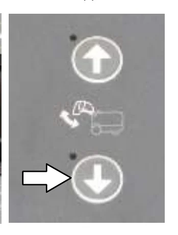
S30 XP and X4 panel with a hopper icon and a down arrow button, with an arrow pointing to the lower button
S30 XP and X4

ENGAGING THE HOPPER SUPPORT BAR

In short The hopper support bar keeps a raised hopper from falling, so engage it whenever you leave the hopper raised. Set the parking brake, start the machine, raise the hopper fully, rotate the bar down into the clip, lower the hopper onto the bracket and turn the machine off.‌‌​⁠‍⁠​​⁠⁠‍‌‌‍‍‌⁠‍‌​​​​​​‌‍⁠​​​‌​⁠​​‌⁠⁠​⁠‌​‌​‌​​⁠​⁠‌⁠‌‌⁠⁠​‍⁠

The hopper support bar prevents the raised hopper from falling. Always engage the hopper support bar whenever leaving the hopper in the raised position.

  1. Set the parking brake.
  2. Start the machine.
  3. Completely raise the hopper.
Close-up of the S30 control panel with an arrow pointing to the hopper raise switch
S30
S30 XP and X4 panel with an arrow pointing to the hopper raise (up arrow) button
S30 XP and X4
WARNING: Lift arm pinch point. Stay clear of hopper lift arms.
FOR SAFETY: When using machine, make sure adequate clearance is available before raising hopper.
  1. Rotate the support bar down into the hopper support clip.
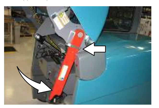
Red hopper support bar being rotated down into the hopper support clip, with arrows showing the clip and the rotation direction
WARNING: Raised hopper may fall. Engage hopper support bar.
  1. Lower the hopper to lower the hopper support bar onto the bracket.
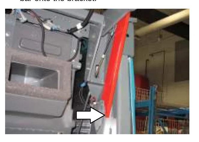
Red hopper support bar resting on the bracket after the hopper is lowered, with an arrow pointing to the bracket
  1. Turn off the machine.
Source: Tennant S30 Diesel Operator Manual 9004087 Rev. 09 (4-2015), page 27, used with permission. SES ref PF-6J5X-ZKAL‌‌​⁠‍⁠​​⁠⁠‍‌‌‍‍‌⁠‍‌​​​​​​‌‍⁠​​​‌​⁠​​‌⁠⁠​⁠‌​‌​‌​​⁠​⁠‌⁠‌‌⁠⁠​‍⁠
S30 Diesel 9004087 (Rev. 09 (4-2015))Page 27 of 74
OPERATION

DISENGAGING THE HOPPER SUPPORT BAR

In short This procedure releases the hopper support bar so the hopper can be lowered. Raise the hopper completely, set the parking brake, rotate the bar up into its storage clip, then lower the hopper.‌‌​⁠‍⁠​​⁠⁠‍‌‌‍‍‌⁠‍‌​​​​​​‌⁠​​​​‌​⁠​​⁠⁠‍‍​‌⁠​‍‌⁠​‌⁠‍​‍⁠‍‍‌‍⁠‌
  1. Start the machine.
  2. Completely raise the hopper.
Close-up of the S30 hopper rocker switch with an arrow pointing to the switch to raise the hopper
S30
Close-up of the S30 XP and X4 control panel with an arrow pointing to the up arrow button used to raise the hopper
S30 XP and X4
  1. Set the parking brake.
  2. Rotate the hopper support bar up into the storage clip.
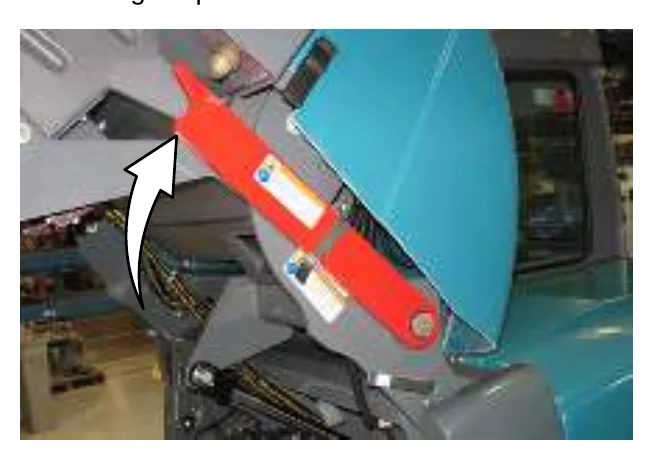
Red hopper support bar beside the teal hopper, with a curved arrow showing it rotating upward into the storage clip
  1. Completely lower the hopper.
WARNING: Lift arm pinch point. Stay clear of hopper lift arms.
Source: Tennant S30 Diesel Operator Manual 9004087 Rev. 09 (4-2015), page 28, used with permission. SES ref PF-W3QL-SDQ2‌‌​⁠‍⁠​​⁠⁠‍‌‌‍‍‌⁠‍‌​​​​​​‌⁠​​​​‌​⁠​​⁠⁠‍‍​‌⁠​‍‌⁠​‌⁠‍​‍⁠‍‍‌‍⁠‌
S30 Diesel 9004087 (Rev. 09 (4-2015))Page 28 of 74
OPERATION

DISPLAY MODULE FAULT INDICATORS (S30)

In short The fault indicator lights come on when a fault has occurred, and the machine must be stopped right away. Use the table to find the cause and remedy for each numbered light.‌‌​⁠‍⁠​​⁠⁠‍‌‌‍‍‌⁠‍‌​​​​​​‌⁠‌​​​‌​⁠​​⁠​​‍‌‌‌‍‍​‌‌‌‌⁠‍‌‌​⁠⁠‍‍​

The fault indicator lights illuminate when a fault has occurred. Stop the machine immediately and correct the problem if these indicators come on.‌‌​⁠‍⁠​​⁠⁠‍‌‌‍‍‌⁠‍‌​​​​​​‌⁠‌​​​‌​⁠​​⁠​​‍‌‌‌‍‍​‌‌‌‌⁠‍‌‌​⁠⁠‍‍​

Refer to the table below to determine the cause and remedy for the fault.
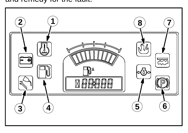
Display module drawing with eight numbered fault indicator lights, each marked by an arrow: 1 water temperature and 2 charging system at upper left, 3 maintenance and 4 fuel level at lower left, 8 hopper fire and 7 clogged dust filter at upper right, 5 engine oil pressure and 6 parking brake at lower right, around a central gauge and hour display
Fault IndicatorsCause(s)Remedy
1: Water Temperature (Red)Engine coolant is too hot to safely operate the machineShut off machine.
Contact TENNANT service representative.
2: Charging System (Amber)Alternator is not charging the battery.Shut off machine.
Contact TENNANT service representative.
3: Maintenance (Amber)Not UsedNot Used
4: Fuel Level (Red)Fuel level is low.Refuel
5: Engine Oil Pressure (Red)Oil pressure is below the normal operating pressureShut off machine.
Contact TENNANT service representative.
6: Parking Brake (Amber)Not UsedNot Used
7: Clogged Dust Filter (Amber)Dust filter is cloggedActivate the filter shaker.
8: Hopper Fire (Red)Fire in the hopperShut off machine.
Extinguish fire.
If necessary, call emergency personnel.
Source: Tennant S30 Diesel Operator Manual 9004087 Rev. 09 (4-2015), page 29, used with permission. SES ref PF-YZ2R-DAZD‌‌​⁠‍⁠​​⁠⁠‍‌‌‍‍‌⁠‍‌​​​​​​‌⁠‌​​​‌​⁠​​⁠​​‍‌‌‌‍‍​‌‌‌‌⁠‍‌‌​⁠⁠‍‍​
S30 Diesel 9004087 (Rev. 09 (4-2015))Page 29 of 74
OPERATION

FAULT INDICATOR(S) (S30 XP and X4)

In short Machines with this feature show faults with a blinking red indicator light, an LCD fault code and an audible alarm. Use the table to find the cause and remedy for each code.‌‌​⁠‍⁠​​⁠⁠‍‌‌‍‍‌⁠‍‌​​​​​​‌⁠‍​​​‌​⁠​​‌​​‌‍‍‌​​⁠‌​​⁠‍‌⁠⁠⁠‌​‍​‍

This machine is equipped with two visual indicators, a red indicator light and an LCD (liquid crystal display).‌‌​⁠‍⁠​​⁠⁠‍‌‌‍‍‌⁠‍‌​​​​​​‌⁠‍​​​‌​⁠​​‌​​‌‍‍‌​​⁠‌​​⁠‍‌⁠⁠⁠‌​‍​‍

The red indicator light will blink continuously indicating that a fault has occurred.
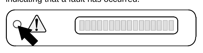
Instrument panel strip showing a red indicator light circle and a warning triangle with an exclamation mark, with a black arrow pointing to the indicator light, next to the LCD display

The LCD will display a fault code. If there is more than one fault, each fault will alternately display.

Instrument panel strip showing the indicator light circle and warning triangle, with a black arrow pointing to the LCD fault display

All faults are also accompanied by an audible alarm to alert the operator a fault has occurred.

Refer to the table below to determine the cause and remedy for the fault.
Fault Code (Displayed in LCD)Cause(s)ResultRemedy
F3: CLOGGED HYD FILTERHydraulic filter is clogged−Shut off machine.
Contact TENNANT service representative.
F4: SHAKER FILTERHopper dust filter is clogged−Activate filter shaker to unclog hopper dust filter.
F5: HOPPER FIREFire in the hopperTerminates sweeping functions and closes hopper doorShut off machine.
Extinguish fire.
If necessary, call emergency personnel.
F6: ALTERNATORAlternator not charging−Contact TENNANT service representative.
F7: LOW OIL PRESSEngine oil pressure is lowShuts down engineContact TENNANT service representative.
F8: HIGH ENG TEMPEngine temperature is highShuts down engineShut off machine.
Contact TENNANT service representative.
F9: HIGH HYD TEMPHydraulic fluid temperature is highCancels 1−Step sweep functionsShut off machine.
Contact TENNANT service representative.
F10: LOW FUELLow fuel−Fill fuel tank.
F18: HOPPER UPHopper is upTerminates sweeping functions−Lower hopper completely.
F20: UP KEY ERRHopper up button failurePrevents all panel operationsShut off machine.
Contact TENNANT service representative.
F21: DN KEY ERRHopper down button failurePrevents all panel operationsShut off machine.
Contact TENNANT service representative.
F22: OPN KEY ERRHopper door open button failurePrevents all panel operationsShut off machine.
Contact TENNANT service representative.
F23: CL KEY ERRHopper door close button failurePrevents all panel operationsShut off machine.
Contact TENNANT service representative.
F24: SEAT SWITCH (Option)Operator not in the seat while engine is running and parking brake not engagedEngine will shut offEngage parking brake before leaving the machine.
Source: Tennant S30 Diesel Operator Manual 9004087 Rev. 09 (4-2015), page 30, used with permission. SES ref PF-HM6I-ORYL‌‌​⁠‍⁠​​⁠⁠‍‌‌‍‍‌⁠‍‌​​​​​​‌⁠‍​​​‌​⁠​​‌​​‌‍‍‌​​⁠‌​​⁠‍‌⁠⁠⁠‌​‍​‍
S30 Diesel 9004087 (Rev. 09 (4-2015))Page 30 of 74
OPERATION

DASH FAULT INDICATORS

In short The dash fault indicators light up when the machine has a fault. Stop the machine right away and use the table to find the cause and remedy for each warning light.‌‌​⁠‍⁠​​⁠⁠‍‌‌‍‍‌⁠‍‌​​​​​​‌⁠⁠​​​‌​⁠​​‍‍⁠‌‌‌‌‌‌​⁠⁠‍‌​‌​‍‍​‌​‍‌

The dash fault indicators illuminate when a fault has occurred. Stop the machine immediately and correct the problem if these indicators come on.‌‌​⁠‍⁠​​⁠⁠‍‌‌‍‍‌⁠‍‌​​​​​​‌⁠⁠​​​‌​⁠​​‍‍⁠‌‌‌‌‌‌​⁠⁠‍‌​‌​‍‍​‌​‍‌

Refer to the table below to determine the cause and remedy for the fault.

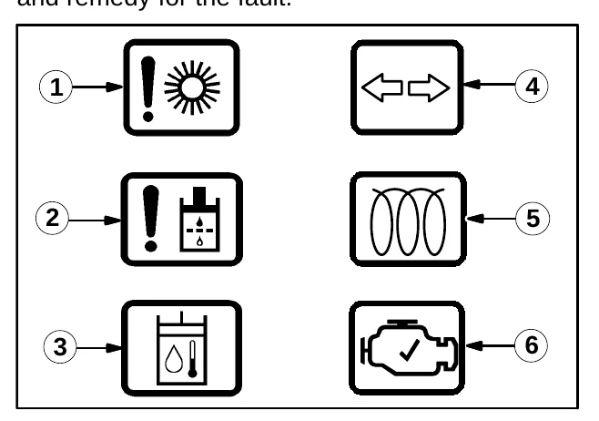
Six dash warning light symbols with numbered callouts 1 to 6: 1 stalled brush, 2 hydraulic filter, 3 hydraulic temperature, 4 hazard flasher arrows, 5 glow plug preheat coil, 6 check engine
Warning LightCause(s)Remedy
1: Stalled BrushOne of the brushes is stalledShut off machine and remove obstructions preventing brushes from operating
2: Hydraulic FilterHydraulic filter is cloggedShut off machine.
Contact TENNANT service representative
3: Hydraulic TemperatureHydraulic system is too hot to safely operate the machineShut off machine.
Contact TENNANT service representative
4: Hazard FlasherNot UsedNot Used
5: Glow Plug − PreheatThis comes on when the igntition switch is turned to the preheat positionThis goes out immediately after engine is started
6: Check EngineEngine control system detects a fault during machine operationShut off machine.
Contact TENNANT service representative
Source: Tennant S30 Diesel Operator Manual 9004087 Rev. 09 (4-2015), page 31, used with permission. SES ref PF-A4ZI-G2DH‌‌​⁠‍⁠​​⁠⁠‍‌‌‍‍‌⁠‍‌​​​​​​‌⁠⁠​​​‌​⁠​​‍‍⁠‌‌‌‌‌‌​⁠⁠‍‌​‌​‍‍​‌​‍‌
S30 Diesel 9004087 (Rev. 09 (4-2015))Page 31 of 74
OPERATION

OPTIONS

WAND (OPTION)

In short The optional vacuum wand and blower wand reach debris outside the machine's sweeping path. Raise the brushes, stop the machine, connect the hose to the wand and the machine, then start the vacuum fan to use it.‌‌​⁠‍⁠​​⁠⁠‍‌‌‍‍‌⁠‍‌​​​​​​‍​​​​​‌​⁠​​‍‍‍​‍‍‍​​​‌‍​‍‍​​‍‌‌​‌⁠⁠

The vacuum wand allows the operator to pick-up debris that is out of reach of the machine’s sweeping path. The blower wand allows the operator to blow debris out from areas that are out of reach of the machine’s sweeping path.‌‌​⁠‍⁠​​⁠⁠‍‌‌‍‍‌⁠‍‌​​​​​​‍​​​​​‌​⁠​​‍‍‍​‍‍‍​​​‌‍​‍‍​​‍‌‌​‌⁠⁠

WARNING: Accident may occur. Do not operate vacuum or blower wand while driving.
  1. Raise the brushes.
  2. Stop the machine and turn off the engine.

FOR SAFETY: Before leaving or servicing machine, stop on level surface, set parking brake, turn off machine, and remove key.

  1. Connect the hose assembly to the wand.

NOTE: The vacuum wand or the blower wand use the same hose assembly.

  1. Attach the vacuum wand hose to the machine under the vacuum wand door located on the front of the hopper. Make sure the hopper door is closed when operating the vacuuum wand.
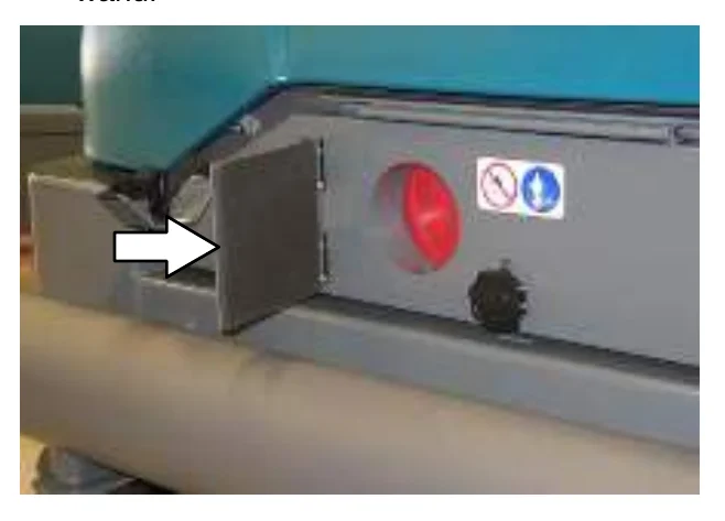
Photo of the front of the hopper with the vacuum wand door open and a white arrow pointing to the door opening, with a red knob and a black fitting beside it
  1. Attach the blower wand hose to the machine under the blower wand door located on the left side of the machine. Make sure the hopper door is open when operating the blower wand.
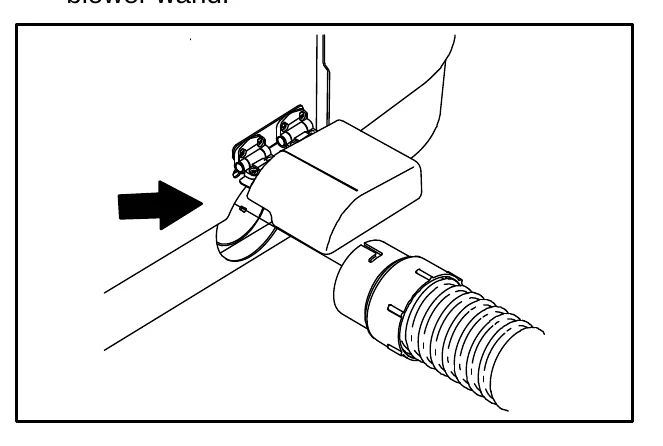
Drawing of the blower wand hose attached to the machine under the blower wand door, with a black arrow pointing at the connection
  1. Start the machine.
WARNING: Machine emits toxic gases. Severe respiratory damage or asphyxiation can result. Provide adequate ventilation. Consult with your regulatory authorities for exposure limits. Keep engine properly tuned.
  1. S30: Press the Wand switch to start the vacuum fan. Then set the engine to high speed.

    S30 XP and X4: Press the Vacuum fan button to start the vacuum fan. The engine will automatically set to the high speed.
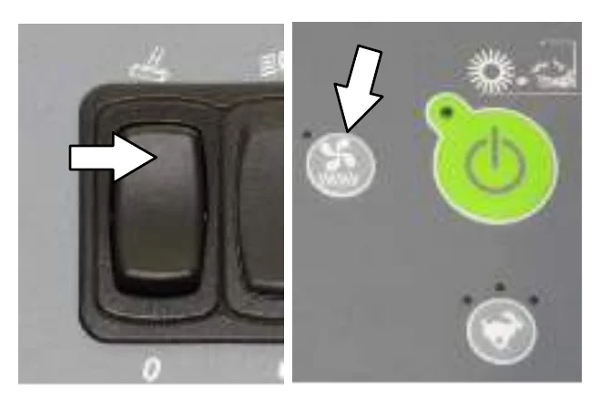
Two photos of the controls: on the left, the S30 rocker Wand switch with an arrow pointing to it; on the right, the S30 XP and X4 panel with the Vacuum fan button marked by an arrow
S30 / S30 XP and X4
  1. Clean the area as needed.
  2. S30: Press the Wand switch to shut off the vacuum fan. Then set the engine to idle speed.

    S30 XP and X4: Press the Vacuum fan button to shut off the vacuum fan. Then set the engine to idle speed.
Source: Tennant S30 Diesel Operator Manual 9004087 Rev. 09 (4-2015), page 32, used with permission. SES ref PF-6QDZ-WDGG‌‌​⁠‍⁠​​⁠⁠‍‌‌‍‍‌⁠‍‌​​​​​​‍​​​​​‌​⁠​​‍‍‍​‍‍‍​​​‌‍​‍‍​​‍‌‌​‌⁠⁠
S30 Diesel 9004087 (Rev. 09 (4-2015))Page 32 of 74
OPERATION
  1. Shut the machine off.
  2. Disconnect the wand from the machine and return it to the storage location.

HEATER / AIR CONDITIONER CONTROLS (OPTION)

In short The optional cab has a heater/air conditioner switch, a temperature knob and a fan knob. The switch selects air conditioner, off or heater, and the knobs set temperature and fan speed.‌‌​⁠‍⁠​​⁠⁠‍‌‌‍‍‌⁠‍‌​​​​​​‍​‌​​​‌​⁠​​‍‍​‌​‍‌​​​⁠‍​⁠​‍⁠‌‍‍​‌‍‌

Use the Heater / Air conditioner switch to turn on the heater or air conditioner.‌‌​⁠‍⁠​​⁠⁠‍‌‌‍‍‌⁠‍‌​​​​​​‍​‌​​​‌​⁠​​‍‍​‌​‍‌​​​⁠‍​⁠​‍⁠‌‍‍​‌‍‌

Top position: Air conditioner

Middle position: Off

Bottom position: Heater
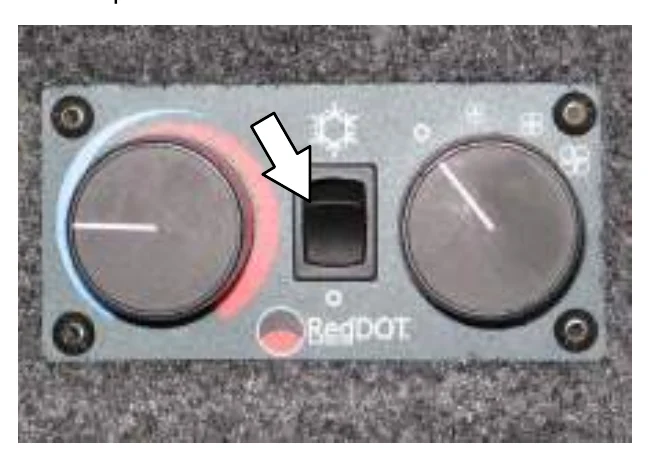
Heater / air conditioner control panel with a large temperature knob, a rocker switch and a fan knob; an arrow points to the rocker switch in the middle

Use the Temperature knob to control the cab heater temperature. Use the Fan knob to control the air conditioner temperature.
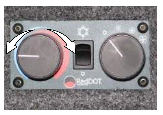
Same control panel with curved double-headed arrows around the large temperature knob showing it turns both ways

Use the Fan knob to control the fan speed. This knob affects the heater and air conditioner.
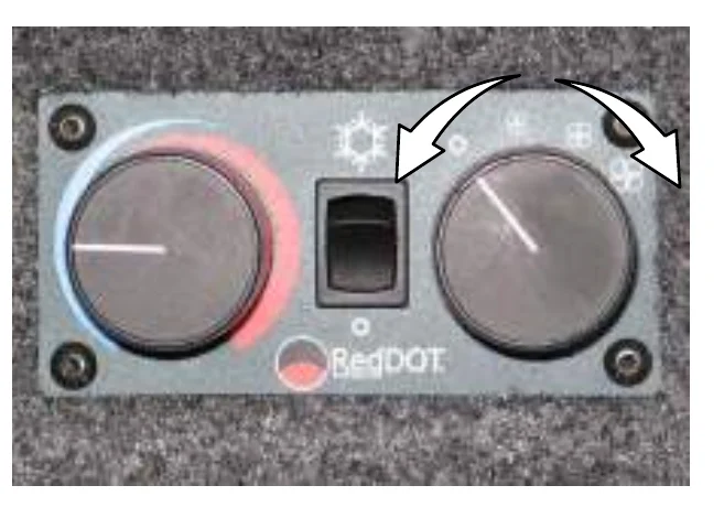
Control panel with curved arrows at the rocker switch and the right-hand fan knob showing it turns both ways

WINDSHIELD WIPER SWITCH (OPTION)

In short The optional windshield wiper switch turns the wiper on and sets its speed: top is high, middle is low, bottom is off.

Use the Windshield wiper switch to turn on and adjust the windshield wiper speed.

Top position: High

Middle position: Low

Bottom position: Off
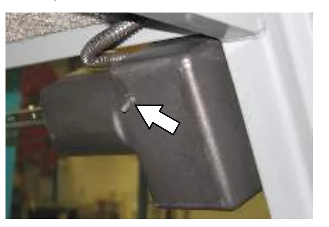
Windshield wiper motor housing under the cab roof with an arrow pointing to the wiper switch

CAB LIGHT SWITCH (OPTION)

In short The optional cab light is operated by pressing its switch.

Press the Cab light switch to operate the cab light.
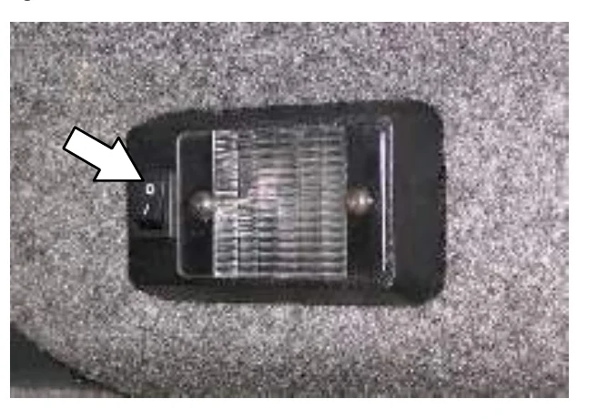
Cab dome light with an arrow pointing to its small switch on the left side
Source: Tennant S30 Diesel Operator Manual 9004087 Rev. 09 (4-2015), page 33, used with permission. SES ref PF-U6IH-KUCM‌‌​⁠‍⁠​​⁠⁠‍‌‌‍‍‌⁠‍‌​​​​​​‍​‌​​​‌​⁠​​‍‍​‌​‍‌​​​⁠‍​⁠​‍⁠‌‍‍​‌‍‌
S30 Diesel 9004087 (Rev. 09 (4-2015))Page 33 of 74
OPERATION

OPERATION

TOWER BUMPERS (OPTION)

In short The tower bumpers protect the rear engine cover if the machine is backed into an obstruction. They must be opened before the rear engine shroud is opened, and closed and secured before the machine is operated.‌‌​⁠‍⁠​​⁠⁠‍‌‌‍‍‌⁠‍‌​​​​​​‍​‍​​​‌​⁠​​‍‌⁠​​‍⁠​‌​⁠⁠⁠‌​​‍​​⁠‌‍‍⁠

The tower bumpers help protect the rear engine cover from being damaged if the machine is backed into an obstruction. Open the tower bumpers before opening rear engine shroud.‌‌​⁠‍⁠​​⁠⁠‍‌‌‍‍‌⁠‍‌​​​​​​‍​‍​​​‌​⁠​​‍‌⁠​​‍⁠​‌​⁠⁠⁠‌​​‍​​⁠‌‍‍⁠

To open the bumpers:

  1. Pull the pin from the bracket and the bumper.
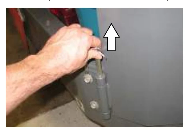
    Hand pulling the pin upward out of the bracket and bumper at the rear of the machine, with an arrow pointing up
  2. Open the bumper.
    Rear of the machine with the tower bumper swung open, and a curved arrow showing the direction the bumper opens
  3. Close and secure the tower bumpers before operating the machine.

TURN SIGNAL SWITCH (OPTION)

In short The optional turn signal switch indicates the direction of a turn. Pull it out to activate the flashers, and return it manually to the off position after the turn.

Use the Turn signal switch to indicate the direction of the turn. The switch must be manually returned to the off position after the turn. Pull the switch out to activate the flashers.
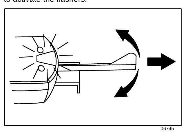
Drawing of the turn signal switch with flashing light rays at the left, curved arrows showing the switch moving up and down, and a bold arrow pointing right showing pulling the switch out
06745
Source: Tennant S30 Diesel Operator Manual 9004087 Rev. 09 (4-2015), page 34, used with permission. SES ref PF-2NOV-T2MA‌‌​⁠‍⁠​​⁠⁠‍‌‌‍‍‌⁠‍‌​​​​​​‍​‍​​​‌​⁠​​‍‌⁠​​‍⁠​‌​⁠⁠⁠‌​​‍​​⁠‌‍‍⁠
S30 Diesel 9004087 (Rev. 09 (4-2015))Page 34 of 74
OPERATION

MACHINE TROUBLESHOOTING

In short This table lists problems with dusting, sweeping performance and sweeping functions, with the likely cause and the remedy for each. Many remedies are to replace or adjust a part, and some call for a Tennant service representative.‌‌​⁠‍⁠​​⁠⁠‍‌‌‍‍‌⁠‍‌​​​​​​‍​⁠​​​‌​⁠​​‍⁠‍‌‍​‌​‌‍​​⁠‌‌⁠​‌​‌‌‌‍​
ProblemCauseRemedy
Excessive dustingBrush skirts and dust seals worn, damaged, out of adjustmentReplace or adjust brush skirts or dust seals
Dust filter cloggedShake and/or replace dust filter
Cyclones dirty / cloggedClear blockage from cyclones
Vacuum hose damagedReplace vacuum hose
Vacuum fan seal damagedReplace vacuum fan seal
Vacuum fan failureEnsure Thermo Sentry wires are connected
Call Tennant service representative
Thermo−Sentry trippedAllow Thermo−Sentry to cool
Poor sweeping performanceWorn brush bristlesReplace brushes
Brush pressure set too lightIncrease brush pressure
Main brush not properly adjustedAdjust brush
Debris caught in main brush drive mechanismRemove debris from main brush drive mechanism
Main and/or side brush drive failureCall Tennant service representative
Hopper is fullEmpty hopper
Hopper lip skirts worn or damagedReplace lip skirts
Improper brushesRefer to Brush Information or call Tennant service representative
Engine speed set wrongSet engine speed correctly
Sweeping functions do not turn onHopper is upCompletely lower hopper
Fire in the hopperShut off machine. Extinguish fire. If necessary, call emergency personnel
S30 XP and X4: Hydraulic fluid too hotCall Tennant service representative
Source: Tennant S30 Diesel Operator Manual 9004087 Rev. 09 (4-2015), page 35, used with permission. SES ref PF-XHDW-BKXS‌‌​⁠‍⁠​​⁠⁠‍‌‌‍‍‌⁠‍‌​​​​​​‍​⁠​​​‌​⁠​​‍⁠‍‌‍​‌​‌‍​​⁠‌‌⁠​‌​‌‌‌‍​
S30 Diesel 9004087 (Rev. 09 (4-2015))Page 35 of 74
MAINTENANCE

MAINTENANCE

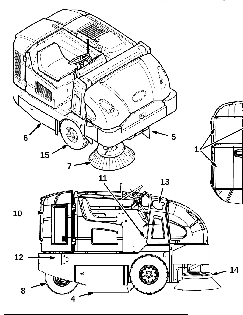
Three views of the sweeper (front-left perspective, top view and side view) with numbered callouts 1 to 16 marking the maintenance and service points

MAINTENANCE CHART

In short This chart lists each maintenance procedure by interval, who is responsible (operator or trained personnel), the lubricant or fluid to use and the number of service points. The daily checks shown here are all done by the operator.‌‌​⁠‍⁠​​⁠⁠‍‌‌‍‍‌⁠‍‌​​​​​​‍‌‌​​​‌​⁠​​‍‌⁠⁠​​​‍⁠​‍⁠‌​⁠​‍⁠‌‍‌⁠⁠‌

The table below indicates the Person Responsible for each procedure.
O = Operator.
T = Trained Personnel.‌‌​⁠‍⁠​​⁠⁠‍‌‌‍‍‌⁠‍‌​​​​​​‍‌‌​​​‌​⁠​​‍‌⁠⁠​​​‍⁠​‍⁠‌​⁠​‍⁠‌‍‌⁠⁠‌

IntervalPerson Resp.KeyDescriptionProcedureLubricant/FluidNo. of Service Points
DailyO1EngineCheck oil levelEO1
Check coolant level in reservoirWG1
Check air filter indicator−1
O2Hydraulic fluid reservoirCheck fluid levelHYDO1
O3Dust filterShake to clean−1
O4Main brush compartment skirtsCheck for damage, wear, and adjustment−All
O5Hopper skirtsCheck for damage, wear, and adjustment−All
Source: Tennant S30 Diesel Operator Manual 9004087 Rev. 09 (4-2015), page 37, used with permission. SES ref PF-JBTF-SLHB‌‌​⁠‍⁠​​⁠⁠‍‌‌‍‍‌⁠‍‌​​​​​​‍‌‌​​​‌​⁠​​‍‌⁠⁠​​​‍⁠​‍⁠‌​⁠​‍⁠‌‍‌⁠⁠‌
S30 Diesel 9004087 (Rev. 09 (4-2015))Page 37 of 74
MAINTENANCE

MAINTENANCE

In short This chart lists each maintenance procedure by interval (daily, 50, 100 and 200 hours), who is responsible (Operator or Trained Personnel), the lubricant or fluid to use, and the number of service points. The lubricant codes are listed below the table.‌‌​⁠‍⁠​​⁠⁠‍‌‌‍‍‌⁠‍‌​​​​​​‍‌‍​​​‌​⁠​​‌​​‌⁠‌​​⁠​​‍⁠⁠​​‌⁠⁠​‍⁠​​

The table below indicates the Person Responsible for each procedure.
O = Operator.
T = Trained Personnel.‌‌​⁠‍⁠​​⁠⁠‍‌‌‍‍‌⁠‍‌​​​​​​‍‌‍​​​‌​⁠​​‌​​‌⁠‌​​⁠​​‍⁠⁠​​‌⁠⁠​‍⁠​​

IntervalPerson Resp.KeyDescriptionProcedureLubricant/FluidNo. of Service Points
DailyO6Main brushCheck for damage and wear−1
DailyO7Side brushCheck for damage and wear−1
50 HoursO6Main brushRotate end-for-end−1
50 HoursT6Main brushCheck brush pattern and adjust if needed−1
50 HoursT8Rear wheelTorque wheel nuts (after initial 50 hours only)−1
50 HoursT9BatteryClean and tighten battery cable connections (after initial 50 hours only)−1
50 HoursT1EngineCheck belt tension−1
50 HoursT1Fuel linesCheck for damage and wear and tighten loose clamp bands−1
100 HoursT1EngineChange oil and filterEO1
100 HoursT3Dust filterCheck for damage, clean or replace−1
100 HoursT16Cyclones / filter housingClean−All
100 HoursT16Cyclone sealsCheck for damage or wear−All
100 HoursT10RadiatorClean core exterior−1
100 HoursT2Hydraulic coolerClean core exteriorHYDO1
100 HoursO8Rear tireCheck pressure−1
100 HoursO−SealsCheck for damage or wear−All
200 HoursT10Radiator hoses and clampsCheck for tightness and wear−All
200 HoursT11Brake pedalCheck adjustment−1
200 HoursT12Rear wheel support bearings (S30 and S30 XP)LubricateSPL2
NOTE: Change the hydraulic fluid, filter, and suction strainer, indicated (*), after every 800 hours for machines NOT originally equipped with TennantTrue premium hydraulic fluid. (See Hydraulics section).

LUBRICANT/FLUID

EO . . . . 10W−30, 10W−40, or 15W−40 Engine oil, API diesel classification CF or better.
HYDO . TennantTrue premium hydraulic fluid or equivalent
WG . . . Water and ethylene glycol anti-freeze, −34° C (−30° F)
SPL . . . Special lubricant, Lubriplate EMB grease (Tennant part number 01433−1)

NOTE: More frequent maintenance intervals may be required in extremely dusty conditions.
Source: Tennant S30 Diesel Operator Manual 9004087 Rev. 09 (4-2015), page 38, used with permission. SES ref PF-FHKN-HUFA‌‌​⁠‍⁠​​⁠⁠‍‌‌‍‍‌⁠‍‌​​​​​​‍‌‍​​​‌​⁠​​‌​​‌⁠‌​​⁠​​‍⁠⁠​​‌⁠⁠​‍⁠​​
S30 Diesel 9004087 (Rev. 09 (4-2015))Page 38 of 74
MAINTENANCE

MAINTENANCE

The table below indicates the Person Responsible for each procedure.‌‌​⁠‍⁠​​⁠⁠‍‌‌‍‍‌⁠‍‌​​​​​​‍‌⁠​​​‌​⁠​​‌⁠​‌​⁠‌​‍⁠‍⁠‌​‌‍‌‌​​‍‌‍‍

O = Operator.
T = Trained Personnel.

In short This chart lists what service each part of the machine needs at 200, 400, 800, 1200 and 2400 hours, who may do it, and which lubricant or fluid to use. All listed jobs are for trained personnel.‌‌​⁠‍⁠​​⁠⁠‍‌‌‍‍‌⁠‍‌​​​​​​‍‌⁠​​​‌​⁠​​‌⁠​‌​⁠‌​‍⁠‍⁠‌​‌‍‌‌​​‍‌‍‍
IntervalPerson Resp.KeyDescriptionProcedureLubricant/FluidNo. of Service Points
200 HoursT12Steering cylinder bearings
(S30 and S30 XP)
(S/N 000000-006766)
LubricateSPL1
T12Steering spindles
(S30 X4)
LubricateSPL2
T12Steering rod (S30 X4)LubricateSPL1
T13Hopper lift arm bearingsLubricateSPL2
T14Side brush guardRotate 90°-1
400 HoursT1EngineReplace fuel filter-1
T15Front wheelsAdjust and repack bearingsSPL2
800 HoursT2Hydraulic fluid reservoirReplace filler cap-1
T-Hydraulic hosesCheck for wear and damage-All
T10Cooling systemFlushWG1
T8Propelling motorTorque shaft nut-1
T8Rear wheelTorque wheel nuts-1
T9BatteryClean and tighten battery cable connections-1
1200 HoursT2Hydraulic fluid filter* Change filter element-All
2400 HoursT2Hydraulic fluid reservoir* Replace suction strainer-1
* Change hydraulic fluidHYDO1
NOTE: Change the hydraulic fluid, filter, and suction strainer, indicated (*), after every 800 hours for machines NOT originally equipped with TennantTrue premium hydraulic fluid. (See Hydraulics section).

LUBRICANT/FLUID

  • EO . . . . 10W-30, 10W-40, or 15W-40 Engine oil, API diesel classification CF or better.
  • HYDO . TennantTrue premium hydraulic fluid or equivalent
  • WG . . . Water and ethylene glycol anti-freeze, -34° C (-30° F)
  • SPL . . . Special lubricant, Lubriplate EMB grease (Tennant part number 01433-1)
NOTE: More frequent maintenance intervals may be required in extremely dusty conditions.
Source: Tennant S30 Diesel Operator Manual 9004087 Rev. 09 (4-2015), page 39, used with permission. SES ref PF-JDAT-RPOA‌‌​⁠‍⁠​​⁠⁠‍‌‌‍‍‌⁠‍‌​​​​​​‍‌⁠​​​‌​⁠​​‌⁠​‌​⁠‌​‍⁠‍⁠‌​‌‍‌‌​​‍‌‍‍
S30 Diesel 9004087 (Rev. 09 (4-2015))Page 39 of 74
MAINTENANCE

MAINTENANCE

LUBRICATION

In short This section covers lubricating the machine and checking the engine oil. Check the engine oil daily and change the oil and filter every 100 hours; grease the rear wheel support, steering cylinder and hopper lift arm bearings every 200 hours.‌‌​⁠‍⁠​​⁠⁠‍‌‌‍‍‌⁠‍‌​​​​​​‍‍​​​​‌​⁠​​⁠‍⁠⁠‍‌⁠‍⁠​⁠‌‌⁠​⁠⁠​​‍‌⁠‌​
FOR SAFETY: Before leaving or servicing machine, stop on level surface, set parking brake, turn off machine, and remove key.

ENGINE OIL

Check the engine oil level daily. Change the oil and oil filter after every 100 hours of operation.‌‌​⁠‍⁠​​⁠⁠‍‌‌‍‍‌⁠‍‌​​​​​​‍‍​​​​‌​⁠​​⁠‍⁠⁠‍‌⁠‍⁠​⁠‌‌⁠​⁠⁠​​‍‌⁠‌​

A hand holding a wrench on the blue engine, working at the engine oil filter area

Fill the engine with oil until the oil is between the indicator marks on the dipstick. DO NOT fill past the top indicator mark. The engine oil capacity is 6 L (6.35 qt) with oil filter.

REAR WHEEL SUPPORT (S30 and S30 XP)

Lubricate the rear wheel support bearings after every 200 hours of operation.

Two white arrows pointing to the grease fittings on the rear wheel support

STEERING CYLINDER BEARING (S30 and S30 XP) (S/N 000000-006766)

Lubricate the steering cylinder after every 200 hours of operation.

A white arrow pointing to the grease fitting on the steering cylinder bearing

HOPPER LIFT ARM BEARINGS

Lubricate the hopper lift arm bearings after every 200 hours of operation.

A hand pointing to the grease fitting on a hopper lift arm bearing
Source: Tennant S30 Diesel Operator Manual 9004087 Rev. 09 (4-2015), page 40, used with permission. SES ref PF-C57N-5EOS‌‌​⁠‍⁠​​⁠⁠‍‌‌‍‍‌⁠‍‌​​​​​​‍‍​​​​‌​⁠​​⁠‍⁠⁠‍‌⁠‍⁠​⁠‌‌⁠​⁠⁠​​‍‌⁠‌​
S30 Diesel 9004087 (Rev. 09 (4-2015))Page 40 of 74
MAINTENANCE

STEERING ROD END (S30 X4)

In short This section covers lubricating the steering rod end and spindles on the S30 X4 every 200 hours of operation.‌‌​⁠‍⁠​​⁠⁠‍‌‌‍‍‌⁠‍‌​​​​​​‍‍‌​​​‌​⁠​​‍‍‌‍⁠​‌​‍‌​‍‌‌​‍⁠​​​‌​⁠⁠

Lubricate the steering rod end and spindles after every 200 hours of operation.‌‌​⁠‍⁠​​⁠⁠‍‌‌‍‍‌⁠‍‌​​​​​​‍‍‌​​​‌​⁠​​‍‍‌‍⁠​‌​‍‌​‍‌‌​‍⁠​​​‌​⁠⁠

Close-up of the steering rod end on the S30 X4 with a white arrow pointing to the lubrication fitting on the rod end

STEERING SPINDLES (S30 X4)

Lubricate the steering after every 200 hours of operation.

Steering spindle housing seen from above with two white arrows pointing to the two grease fittings on the spindle
Second view of the steering spindle housing from underneath with two white arrows pointing to the grease fittings near the hydraulic hoses

FRONT WHEEL BEARINGS

In short The front wheel bearings must be repacked and adjusted every 400 hours of operation.

Repack and adjust the front wheel bearings every 400 hours of operation.

Front wheel of the machine with a white arrow pointing to the wheel hub where the front wheel bearings are located
Source: Tennant S30 Diesel Operator Manual 9004087 Rev. 09 (4-2015), page 41, used with permission. SES ref PF-2HZA-ZTFR‌‌​⁠‍⁠​​⁠⁠‍‌‌‍‍‌⁠‍‌​​​​​​‍‍‌​​​‌​⁠​​‍‍‌‍⁠​‌​‍‌​‍‌‌​‍⁠​​​‌​⁠⁠
S30 Diesel 9004087 (Rev. 09 (4-2015))Page 41 of 74
MAINTENANCE

MAINTENANCE

HYDRAULICS

In short This section covers checking the hydraulic fluid level daily at operating temperature with the hopper down. It also gives the replacement intervals for the fluid, filler cap, strainer and filter.‌‌​⁠‍⁠​​⁠⁠‍‌‌‍‍‌⁠‍‌​​​​​​‍‍‍​​​‌​⁠​​⁠‌⁠‌‌‌​​‍⁠​⁠‌‌​​​​⁠​​‍⁠⁠
FOR SAFETY: Before leaving or servicing machine, stop on level surface, set parking brake, turn off machine, and remove key.

Check the hydraulic fluid level at operating temperature daily. The hopper must be down when checking hydraulic fluid level.‌‌​⁠‍⁠​​⁠⁠‍‌‌‍‍‌⁠‍‌​​​​​​‍‍‍​​​‌​⁠​​⁠‌⁠‌‌‌​​‍⁠​⁠‌‌​​​​⁠​​‍⁠⁠

Gloved hand pulling the dipstick from the hydraulic reservoir filler cap to check the fluid level, with a blue glove-required safety symbol in the corner

A filler cap is mounted on top of the reservoir. It has a built-in breather and fluid level dipstick. Replace the cap after every 800 hours of operation.

Lubricate the filler cap gasket with a film of hydraulic fluid before putting the cap back on the reservoir.

ATTENTION! Do not overfill the hydraulic fluid reservoir or operate the machine with a low level of hydraulic fluid in the reservoir. Damage to the machine hydraulic system may result.

Drain and refill the hydraulic fluid reservoir with new TennantTrue premium hydraulic fluid after every 2400 hours of operation. Machines have a blue colored drop (left photo) on the hydraulic fluid label if originally equipped with TennantTrue premium hydraulic fluid.

WARNING: Burn hazard. Hot surface. Do NOT touch.
Two photos of the hydraulic fluid label near the filler cap with white arrows pointing to it: left shows a blue drop for TennantTrue fluid, right shows a plain drop for previous fluid
TennantTrue Fluid / Previous Fluid
NOTE: Change the hydraulic fluid, filter, and suction strainer after every 800 hours for ALL machines that have NOT consistently used TennantTrue premium hydraulic fluid or equivalent.

The reservoir has a built-in strainer outlet that filters hydraulic fluid before it enters the system. Replace the strainer after every 2400 hours of operation.

Replace the hydraulic fluid filter after every 1200 hours of operation or if the hydraulic reservoir gauge is in the yellow/red zone when the reservoir hydraulic fluid is approximately 32°C (90° F).

Top of the hydraulic reservoir showing the filler cap and the hydraulic fluid filter with its gauge in green and red, a white arrow pointing to the filter, and a glove-required safety symbol
Source: Tennant S30 Diesel Operator Manual 9004087 Rev. 09 (4-2015), page 42, used with permission. SES ref PF-EAND-4QLW‌‌​⁠‍⁠​​⁠⁠‍‌‌‍‍‌⁠‍‌​​​​​​‍‍‍​​​‌​⁠​​⁠‌⁠‌‌‌​​‍⁠​⁠‌‌​​​​⁠​​‍⁠⁠
S30 Diesel 9004087 (Rev. 09 (4-2015))Page 42 of 74
MAINTENANCE

HYDRAULIC FLUID

In short This section lists the three Tennant hydraulic fluids and the ambient air temperature range each is meant for. If you use a locally-available fluid, its specifications must match Tennant's.‌‌​⁠‍⁠​​⁠⁠‍‌‌‍‍‌⁠‍‌​​​​​​‍‍⁠​​​‌​⁠​​‌⁠‍‌‍​​⁠‌⁠‍​​​​‍⁠‌‍‌​​⁠​

There are three fluids available for different temperature ranges:‌‌​⁠‍⁠​​⁠⁠‍‌‌‍‍‌⁠‍‌​​​​​​‍‍⁠​​​‌​⁠​​‌⁠‍‌‍​​⁠‌⁠‍​​​​‍⁠‌‍‌​​⁠​

TennantTrue premium hydraulic fluid (Extended Life)
Part NumberCapacityISO Grade Viscosity Index (VI)Ambient Air Temperature Ranges
10577103.8 L (1 gal)ISO 100
VI 126 or higher
19° C (65° F) or higher
105771119 L (5 gal)
10690193.8 L (1 gal)ISO 68
VI 155 or higher
7 to 43° C (45 to 110° F)
106902019 L (5 gal)
10577073.8 L (1 gal)ISO 32
VI 163 or higher
16° C (60° F) or lower
105770819 L (5 gal)

If using a locally-available hydraulic fluid, be sure the specifications match Tennant hydraulic fluid specifications. Substitute fluids can cause premature failure of hydraulic components.

ATTENTION! Hydraulic components depend on system hydraulic fluid for internal lubrication. Malfunctions, accelerated wear, and damage will result if dirt or other contaminants enter the hydraulic system.

HYDRAULIC HOSES

In short Check the hydraulic hoses for wear or damage after every 800 hours of operation. Use cardboard to locate leaks, and report any leak to appropriate personnel.

Check the hydraulic hoses after every 800 hours of operation for wear or damage.

FOR SAFETY: When servicing machine, use cardboard to locate leaking hydraulic fluid under pressure.

High pressure fluid escaping from a very small hole can almost be invisible, and can cause injury.

A hand holds a piece of cardboard near a hydraulic hose while another hand holds a magnifying glass over a small spray of fluid from a leak; glove and safety goggles symbols are at the left
00002

Contact appropriate personnel if a leak is discovered.

ATTENTION: Only use TENNANT supplied hydraulic hoses or equivalent rated hydraulic hoses.
Source: Tennant S30 Diesel Operator Manual 9004087 Rev. 09 (4-2015), page 43, used with permission. SES ref PF-MNXJ-VZQE‌‌​⁠‍⁠​​⁠⁠‍‌‌‍‍‌⁠‍‌​​​​​​‍‍⁠​​​‌​⁠​​‌⁠‍‌‍​​⁠‌⁠‍​​​​‍⁠‌‍‌​​⁠​
S30 Diesel 9004087 (Rev. 09 (4-2015))Page 43 of 74
MAINTENANCE

ENGINE

In short This section covers engine servicing, starting with the cooling system. Stop on a level surface, set the parking brake, turn off the machine and remove the key first. Check the coolant level daily, check the radiator hoses and clamps every 200 hours, and flush the cooling system every 800 hours.‌‌​⁠‍⁠​​⁠⁠‍‌‌‍‍‌⁠‍‌​​​​​​‍⁠​​​​‌​⁠​​⁠​‌⁠​​‌‌‌⁠⁠‍‌‌‍‌⁠‌‌‍​⁠‍‌
FOR SAFETY: Before leaving or servicing machine, stop on level surface, set parking brake, turn off machine, and remove key.

COOLING SYSTEM

FOR SAFETY: When servicing machine, avoid contact with hot engine coolant. Do not remove cap from radiator when engine is hot. Allow engine to cool.

Check the coolant level in the reservoir daily. The coolant level must be between the indicator marks when the engine is cold.‌‌​⁠‍⁠​​⁠⁠‍‌‌‍‍‌⁠‍‌​​​​​​‍⁠​​​​‌​⁠​​⁠​‌⁠​​‌‌‌⁠⁠‍‌‌‍‌⁠‌‌‍​⁠‍‌

Coolant reservoir beside the radiator with a white arrow pointing to the indicator marks on the side of the tank, which holds green coolant
FOR SAFETY: When servicing machine, do not remove cap from radiator when engine is hot. Allow engine to cool.

Refer to the coolant manufacturer for water/coolant mixing instructions.

Flush the radiator and the cooling system after every 800 hours of operation.

The cooling system must be completely filled with coolant to keep the engine from overheating. When filling the cooling system, open the drain cocks to bleed the air from the system.

Side of the blue engine with a white arrow pointing to a drain cock fitting that is opened to bleed air from the cooling system

Check the radiator hoses and clamps after every 200 hours of operation. Tighten loose clamps. Replace damaged hoses and clamps.

Engine compartment with a white arrow pointing to the upper radiator hose and its clamp, with the coolant reservoir at the lower right
Source: Tennant S30 Diesel Operator Manual 9004087 Rev. 09 (4-2015), page 44, used with permission. SES ref PF-V3Y2-ZVXQ‌‌​⁠‍⁠​​⁠⁠‍‌‌‍‍‌⁠‍‌​​​​​​‍⁠​​​​‌​⁠​​⁠​‌⁠​​‌‌‌⁠⁠‍‌‌‍‌⁠‌‌‍​⁠‍‌
S30 Diesel 9004087 (Rev. 09 (4-2015))Page 44 of 74
MAINTENANCE

Check the radiator core exterior and hydraulic cooler fins for debris after every 100 hours of operation. Blow or rinse (with low pressure air or water) all dust through the grille and radiator fins, in the opposite direction of normal air flow. Be careful to not bend the cooling fins when cleaning. Clean thoroughly to prevent the fins from becoming encrusted with dust. To avoid cracking the radiator, allow the radiator and cooler fins to cool before cleaning.‌‌​⁠‍⁠​​⁠⁠‍‌‌‍‍‌⁠‍‌​​​​​​‍⁠‌​​​‌​⁠​​⁠‌‍​⁠⁠​‍​​‌​‌​⁠⁠⁠‌‌‌​‌​‌

Photo of the radiator and hydraulic cooler in the engine compartment with two white arrows pointing at the cooling fins to be cleaned. Blue round symbols at the left show that protective gloves and eye protection are required.
Source: Tennant S30 Diesel Operator Manual 9004087 Rev. 09 (4-2015), page 45, used with permission. SES ref PF-GGTM-2IFY‌‌​⁠‍⁠​​⁠⁠‍‌‌‍‍‌⁠‍‌​​​​​​‍⁠‌​​​‌​⁠​​⁠‌‍​⁠⁠​‍​​‌​‌​⁠⁠⁠‌‌‌​‌​‌
S30 Diesel 9004087 (Rev. 09 (4-2015))Page 45 of 74
MAINTENANCE

MAINTENANCE

AIR FILTER INDICATOR

In short Check the air filter indicator daily while the engine is running. Do not replace the air filter element until the red line reaches 5 kPa (20 in H2O) and the window is filled with red.‌‌​⁠‍⁠​​⁠⁠‍‌‌‍‍‌⁠‍‌​​​​​​‍⁠‍​​​‌​⁠​​​⁠​‍‌⁠‍‍⁠‌‍⁠​​⁠‍​​​‍‌‌‍⁠

Check the indicator daily. The indicator red line will move as the air filter element fills with dirt. Do not replace the air filter element until the red line reaches 5 kPa (20 in H2O) and the “SERVICE WHEN RED” window is filled with red. The engine must be running to get an accurate air indicator reading.‌‌​⁠‍⁠​​⁠⁠‍‌‌‍‍‌⁠‍‌​​​​​​‍⁠‍​​​‌​⁠​​​⁠​‍‌⁠‍‍⁠‌‍⁠​​⁠‍​​​‍‌‌‍⁠

FOR SAFETY: When servicing machine, avoid moving parts. Do not wear loose clothing, jewelry and secure long hair.
Photo of the air filter indicator mounted near the intake hose, with a white arrow pointing to the red line window on the indicator

AIR FILTER

In short Replace the air filter element when the indicator shows restriction in the air intake system or the element is damaged. Clean the end cap, housing interior and sealing surfaces, then install the element and reinstall the dust cap with the water drain pointing down.
FOR SAFETY: Before leaving or servicing machine, stop on level surface, set parking brake, turn off machine, and remove key.

The engine air filter housing is located in front of the engine compartment inside the left side shroud door.

Replace the air filter element when the air filter indicator shows restriction in the air intake system or the filter element is damaged. Refer to AIR FILTER INDICATOR.

Photo of the engine air filter housing in the engine compartment, with an arrow pointing to the housing

Remove the filter element. Carefully clean the end cap and the interior of the housing with a damp cloth. Clean the housing sealing surfaces.

Photo of a hand pulling the cylindrical air filter element out of the air filter housing

Replace the safety filter element after the primary has been changed three times. Do not remove the safety filter element from the housing unless it is restricting air flow.

Photo of the air filter housing with the primary element removed, an arrow pointing to the blue safety filter element inside

Install the filter element into the air filter housing and reinstall the dust cap with the water drain pointing down.

Photo of the air filter housing with the dust cap reinstalled, an arrow pointing to the water drain pointing down
Source: Tennant S30 Diesel Operator Manual 9004087 Rev. 09 (4-2015), page 46, used with permission. SES ref PF-KZJ7-7DCH‌‌​⁠‍⁠​​⁠⁠‍‌‌‍‍‌⁠‍‌​​​​​​‍⁠‍​​​‌​⁠​​​⁠​‍‌⁠‍‍⁠‌‍⁠​​⁠‍​​​‍‌‌‍⁠
S30 Diesel 9004087 (Rev. 09 (4-2015))Page 46 of 74
MAINTENANCE

Push the reset button on the end of the indicator to reset the air filter indicator after replacing the air filter element.‌‌​⁠‍⁠​​⁠⁠‍‌‌‍‍‌⁠‍‌​​​​​​‍⁠⁠​​​‌​⁠​​‌⁠‌⁠‌​‍‍‌‍⁠‍‌⁠⁠‍‍‍‌‍⁠​​‍

Air filter service indicator mounted on the engine, with a white arrow pointing to the reset button at its end

FUEL FILTER

In short The fuel filter is replaced after every 800 hours of operation. Keep flames and sparks away from the fuel system and keep the area well ventilated while servicing.‌‌​⁠‍⁠​​⁠⁠‍‌‌‍‍‌⁠‍‌​​​​​​‍⁠⁠​​​‌​⁠​​‌⁠‌⁠‌​‍‍‌‍⁠‍‌⁠⁠‍‍‍‌‍⁠​​‍

Replace the fuel filter after every 800 hours of operation.

FOR SAFETY: When servicing machine, keep flames and sparks away from fuel system service area. Keep area well ventilated.
Fuel filter canister on the machine with a white arrow pointing at the filter

FUEL LINES

In short Check the fuel lines every 50 hours and tighten loose clamp bands. Replace the fuel lines and clamp bands every two years, or sooner if worn or damaged, then bleed the fuel system.

Check the fuel lines every 50 hours of operation. If the clamp band is loose, apply oil to the screw of the band and securely tighten the band.

A hand pointing to a fuel line and its clamp band in the engine compartment
A hand holding a rubber fuel line in the engine compartment

The rubber fuel lines can become worn−out whether the engine has been used much or not. Replace the fuel lines and clamp bands every two years.

FOR SAFETY: When servicing machine, keep flames and sparks away from fuel system service area. Keep area well ventilated.

If the fuel lines and clamp bands are found worn or damaged before two years’ time; replace or repair them at once. Bleed the fuel system after replacement of any fuel lines, see PRIMING THE FUEL SYSTEM. When the fuel lines are not installed, plug both ends with clean cloth or paper to prevent dirt from entering the lines. Dirt in the lines can cause fuel injection pump malfunction.

Source: Tennant S30 Diesel Operator Manual 9004087 Rev. 09 (4-2015), page 47, used with permission. SES ref PF-M44G-O36U‌‌​⁠‍⁠​​⁠⁠‍‌‌‍‍‌⁠‍‌​​​​​​‍⁠⁠​​​‌​⁠​​‌⁠‌⁠‌​‍‍‌‍⁠‍‌⁠⁠‍‍‍‌‍⁠​​‍
S30 Diesel 9004087 (Rev. 09 (4-2015))Page 47 of 74
MAINTENANCE

MAINTENANCE

PRIMING THE FUEL SYSTEM

In short Diesel fuel systems normally need priming to remove air, but this machine's fuel system is self-priming because air escapes through the return line.‌‌​⁠‍⁠​​⁠⁠‍‌‌‍‍‌⁠‍‌​​​​​​⁠​​​​​‌​⁠​​‍​⁠⁠​​‌​‍⁠⁠​‍⁠‍‍​‍‍‌‌‍⁠⁠

Typical diesel fuel systems require priming to remove pockets of air from the fuel lines and fuel components. This is usually required after running out of fuel, changing fuel filter elements or repairing a fuel system component. Air in the fuel prevents smooth engine operation.‌‌​⁠‍⁠​​⁠⁠‍‌‌‍‍‌⁠‍‌​​​​​​⁠​​​​​‌​⁠​​‍​⁠⁠​​‌​‍⁠⁠​‍⁠‍‍​‍‍‌‌‍⁠⁠

This fuel system however is self-priming. The return line comes from the top of the injector that allows the air to escape through the return line.

ENGINE BELT

In short Check the engine belt tension after every 50 hours of operation and adjust it as needed to the specified deflection under the specified force.

Check the belt tension after every 50 hours of operation. Adjust tension as necessary. Proper belt tension is 13 mm (0.50 in) from a force of 4 to 5 kg (8 to 10 lb) applied at the mid-point of the longest span.

Drawing of the engine belt routed around three pulleys, with a black arrow pointing at the longest span of the belt
WARNING: Moving belt and fan. Keep away.

BATTERY

In short Clean and tighten the battery connections after the first 50 hours and then every 800 hours. Do not remove the vent plugs or add water to the battery.

Clean and tighten the battery connections after the first 50 hours of operation and after every 800 hours after that. Do not remove the vent plugs from the battery or add water to the battery.

Photo of the battery in the machine with a white arrow pointing to it and a blue protective-glove symbol in the corner
FOR SAFETY: When servicing machine, avoid contact with battery acid.
Source: Tennant S30 Diesel Operator Manual 9004087 Rev. 09 (4-2015), page 48, used with permission. SES ref PF-JMGP-YGEU‌‌​⁠‍⁠​​⁠⁠‍‌‌‍‍‌⁠‍‌​​​​​​⁠​​​​​‌​⁠​​‍​⁠⁠​​‌​‍⁠⁠​‍⁠‍‍​‍‍‌‌‍⁠⁠
S30 Diesel 9004087 (Rev. 09 (4-2015))Page 48 of 74
MAINTENANCE

FUSES AND RELAYS

In short This section covers the fuses and relays in the relay panel. Open the relay panel cover to reach them, and always replace a blown fuse with one of the same amperage.‌‌​⁠‍⁠​​⁠⁠‍‌‌‍‍‌⁠‍‌​​​​​​⁠​‌​​​‌​⁠​​​⁠⁠⁠‍​‌⁠‍​​⁠​‌⁠⁠​​⁠‌​​​‌

RELAY PANEL FUSES AND RELAYS

Remove the relay panel cover to access fuses and relays. Always replace a fuse with a fuse of the same amperage. Extra 15 Amp fuses are provided inside the relay panel drawer on the relay panel.‌‌​⁠‍⁠​​⁠⁠‍‌‌‍‍‌⁠‍‌​​​​​​⁠​‌​​​‌​⁠​​​⁠⁠⁠‍​‌⁠‍​​⁠​‌⁠⁠​​⁠‌​​​‌

Photo of the relay panel with the cover removed, showing five relays on the left and a column of blue fuses on the right, with a white arrow pointing to the panel drawer latch on the right side

Refer to the diagram below for locations of the fuses and relays on the relay panel.

Relay panel layout diagram, TOP to BOTTOM: five relays M1 to M5 on the left, each with terminals 30, 86, 85, 87a and 87, and ten fuse positions F1 to F10 on the right, each with terminals 1 and 2

Refer to the tables below for the fuses and circuits protected.

S30
FuseRatingCircuit Protected
FU115 AHorn
FU215 AKey Switch, Engine, Instrumentation
FU315 ATurn Signals, 4−Way Flashers
FU415 AExtra Fused, Switched B+
FU515 AMain Brush Valves, Side Brush Valves
FU615 AHopper Valves
FU715 ALights, Backup Alarm
FU815 AExtra Fused B+
FU915 AShaker, Vacuum Fan Valve
FU1025 AStarter Solenoid
FU1160 AMain Power Fuse, In Line, In Main Harness
FU1260 ACab Power (Optional)
FU1340 ADiesel Glow Plugs (In Engine Harness)
FU1460 ACab Power (Optional)
S30 XP and X4
FuseRatingCircuit Protected
FU115 AHorn
FU215 AKey Switch, Engine, Instrumentation
FU315 ATurn Signals, 4−Way Flashers, Shaker
FU415 AControl Board
FU515 AMain Brush Valves, Side Brush Valves
FU615 AHopper Valves, Vacuum Fan Valves
FU715 ALights, Backup Alarm
FU815 AExtra Fused B+
FU915 AExtra Switched, Fused B+
FU1025 AStarter Solenoid
FU1160 AMain Power Fuse, In Line, In Main Harness
FU1260 ACab Power (Optional)
FU1340 ADiesel Glow Plugs (In Engine Harness)
FU1460 ACab Power (Optional)
NOTE: Always replace a fuse with a fuse of the same amperage.
Source: Tennant S30 Diesel Operator Manual 9004087 Rev. 09 (4-2015), page 49, used with permission. SES ref PF-VZZR-IHYA‌‌​⁠‍⁠​​⁠⁠‍‌‌‍‍‌⁠‍‌​​​​​​⁠​‌​​​‌​⁠​​​⁠⁠⁠‍​‌⁠‍​​⁠​‌⁠⁠​​⁠‌​​​‌
S30 Diesel 9004087 (Rev. 09 (4-2015))Page 49 of 74
MAINTENANCE

Refer to the tables below for the relays and circuits controlled.‌‌​⁠‍⁠​​⁠⁠‍‌‌‍‍‌⁠‍‌​​​​​​⁠​‍​​​‌​⁠​​‌⁠‍‌‌‍‌‍​‌‌‌⁠⁠⁠‍‌‌⁠​​​‌​

S30
RelayRatingCircuit Controlled
M112 VDC, 40 AHorn
M212 VDC, 40 AAuxiliary 1
M312 VDC, 40 AShaker
M412 VDC, 40 AMain Brush Valves, Side Brush Valves
M512 VDC, 70 AAuxiliary 2
S30 XP and X4
RelayRatingCircuit Controlled
M112 VDC, 40 AHorn
M212 VDC, 40 AAuxiliary 1
M312 VDC, 40 AShaker
M412 VDC, 40 ANot Used
M512 VDC, 40 AAuxiliary 2

ENGINE HARNESS RELAYS

In short This section lists the relays in the engine compartment and the circuit each one controls. Always replace a fuse with one of the same amperage.‌‌​⁠‍⁠​​⁠⁠‍‌‌‍‍‌⁠‍‌​​​​​​⁠​‍​​​‌​⁠​​‌⁠‍‌‌‍‌‍​‌‌‌⁠⁠⁠‍‌‌⁠​​​‌​

The engine harness relays are located inside the engine compartment.

Engine compartment view showing the engine harness relays among wiring, with a white arrow pointing down at the relay location
RelayRatingCircuit Controlled
M912 VDC, 40 AStarter Solenoid
M1012 VDC, 40 AAnti−Restart
M1112 VDC, 40 AFuel Pump
M1212 VDC, 40 AGlow Plug
NOTE: Always replace a fuse with a fuse of the same amperage.

CAB FUSES (CAB OPTION)

In short The cab fuses sit in a fuse box inside the cab behind a removable cover. The table shows which circuit each fuse protects.

The cab fuses are located in the fuse box inside the cab. Remove the fuse cover to access the fuses.

Fuse box cover inside the cab, a gray panel on the carpeted cab wall, with a white arrow pointing to the cover

Refer to the table below for the fuses and circuits controlled.

FuseRatingCircuit Protected
FU15 ALights
FU25 AWiper
FU320 AAir Conditioner
FU42 AHeat
NOTE: Always replace a fuse with a fuse of the same amperage.
Source: Tennant S30 Diesel Operator Manual 9004087 Rev. 09 (4-2015), page 50, used with permission. SES ref PF-BKEG-3Y5U‌‌​⁠‍⁠​​⁠⁠‍‌‌‍‍‌⁠‍‌​​​​​​⁠​‍​​​‌​⁠​​‌⁠‍‌‌‍‌‍​‌‌‌⁠⁠⁠‍‌‌⁠​​​‌​
S30 Diesel 9004087 (Rev. 09 (4-2015))Page 50 of 74
MAINTENANCE

REMOVING AND INSPECTING THE DUST FILTER (SN 000000 − 006500)

In short This section explains how to take out, inspect and reinstall the dust filter. The filter is shaken at the end of every shift, and inspected and cleaned after every 100 hours of operation; damaged filters are replaced.‌‌​⁠‍⁠​​⁠⁠‍‌‌‍‍‌⁠‍‌​​​​​​⁠​⁠​​​‌​⁠​​​‍‍‌​​‌⁠⁠⁠‍​‍‌‍‍​‌⁠‍‍‍‍‌

Shake the dust filter at the end of every shift and before removing the filter from the machine. Inspect and clean the filter after every 100 hours of operation. Replace damaged dust filters.‌‌​⁠‍⁠​​⁠⁠‍‌‌‍‍‌⁠‍‌​​​​​​⁠​⁠​​​‌​⁠​​​‍‍‌​​‌⁠⁠⁠‍​‍‌‍‍​‌⁠‍‍‍‍‌
NOTE: Clean the filter more often if used in extremely dusty conditions.
FOR SAFETY: Before leaving or servicing machine, stop on level surface, set parking brake, turn off machine, and remove key.
  1. Open the top cover and side shroud.
  2. Remove the filter shaker assembly from the filter housing.
Gloved hands lifting the filter shaker assembly out of the filter housing, with an arrow showing the lift direction and a blue glove-required symbol at the lower left
  1. Remove the dust filter from the filter housing.
Gloved hands lifting the round dust filter, with its blue pleated element, up out of the filter housing, with an arrow showing the upward direction
  1. Clean or discard the dust filter element. Refer to CLEANING THE DUST FILTER.
  2. Insert the dust filter into the filter housing and reinstall the removed parts. Be sure the seal is installed as shown below.
Dust filter being set down into the filter housing, with an arrow pointing downward and the filter seal seated around the housing
  1. Close the side shroud and top cover.
Source: Tennant S30 Diesel Operator Manual 9004087 Rev. 09 (4-2015), page 51, used with permission. SES ref PF-F32M-LDHC‌‌​⁠‍⁠​​⁠⁠‍‌‌‍‍‌⁠‍‌​​​​​​⁠​⁠​​​‌​⁠​​​‍‍‌​​‌⁠⁠⁠‍​‍‌‍‍​‌⁠‍‍‍‍‌
S30 Diesel 9004087 (Rev. 09 (4-2015))Page 51 of 74
MAINTENANCE

MAINTENANCE

REMOVING AND INSPECTING THE DUST FILTER (SN 006501 − )

In short This section explains how to shake, remove, inspect and reinstall the dust filter. Shake the filter at the end of every shift, and inspect and clean it after every 100 hours of operation. Replace damaged filters.‌‌​⁠‍⁠​​⁠⁠‍‌‌‍‍‌⁠‍‌​​​​​​⁠‌​​​​‌​⁠​​‌⁠‌​​‍‌​⁠‍‍⁠​‍⁠⁠‍‍​‍​‍​​
FOR SAFETY: Before leaving or servicing machine, stop on level surface, set parking brake, turn off machine, and remove key.

Shake the dust filter at the end of every shift and before removing the filter from the machine. Inspect and clean the filter after every 100 hours of operation. Replace damaged dust filters.‌‌​⁠‍⁠​​⁠⁠‍‌‌‍‍‌⁠‍‌​​​​​​⁠‌​​​​‌​⁠​​‌⁠‌​​‍‌​⁠‍‍⁠​‍⁠⁠‍‍​‍​‍​​

NOTE: Clean the filter more often if used in extremely dusty conditions.
  1. Unlatch and open the hopper cover. Support the hopper cover open with the hopper cover prop rod.
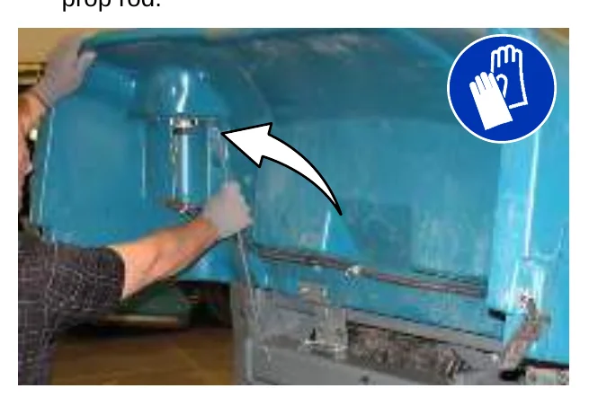
Person wearing a glove lifting the open hopper cover and holding the prop rod, with an arrow showing the rod direction and a blue glove-required safety symbol at the upper right
  1. Remove the dust filter cover.
Top of the dust filter cover on the machine with two curved arrows showing the two latches being rotated to release the cover
  1. Remove the dust filter from the hopper.
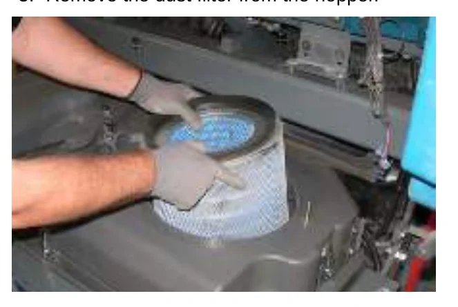
Gloved hands lifting the cylindrical dust filter with blue pleated element out of the hopper
  1. Clean or discard the dust filter element. Refer to CLEANING THE DUST FILTER.
  2. Clean dust and debris from the dust filter tray.
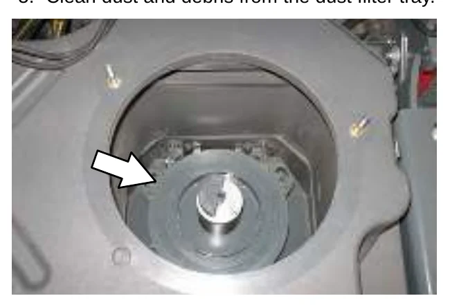
Empty dust filter tray inside the hopper with an arrow pointing to the tray where dust and debris are cleaned
  1. Reinstall the dust filter.
  2. Reinstall the dust filter cover.
  3. Close the hopper cover.
Source: Tennant S30 Diesel Operator Manual 9004087 Rev. 09 (4-2015), page 52, used with permission. SES ref PF-3X6R-SNXY‌‌​⁠‍⁠​​⁠⁠‍‌‌‍‍‌⁠‍‌​​​​​​⁠‌​​​​‌​⁠​​‌⁠‌​​‍‌​⁠‍‍⁠​‍⁠⁠‍‍​‍​‍​​
S30 Diesel 9004087 (Rev. 09 (4-2015))Page 52 of 74
MAINTENANCE

CLEANING THE DUST FILTER

In short The dust filter can be cleaned by shaking, tapping or blowing it with compressed air. Do not damage the filter edges, and wear eye protection when using air at no more than 550 kPa (80 psi).‌‌​⁠‍⁠​​⁠⁠‍‌‌‍‍‌⁠‍‌​​​​​​⁠‌‌​​​‌​⁠​​⁠‍‍‍‌‌‌​‌‍​‍‌⁠‍‍‍​⁠‌‍​‌‌

Use one of the following methods to clean the dust filter:‌‌​⁠‍⁠​​⁠⁠‍‌‌‍‍‌⁠‍‌​​​​​​⁠‌‌​​​‌​⁠​​⁠‍‍‍‌‌‌​‌‍​‍‌⁠‍‍‍​⁠‌‍​‌‌

SHAKING−Press the filter shaker switch.

TAPPING−Tap the filter gently on a flat surface. Do not damage the edges of the filter. The filter will not seal properly if the edges of the filter are damaged.
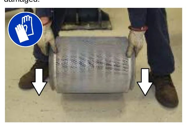
Person in work gloves holding the cylindrical dust filter and tapping it gently on a flat floor, with two arrows pointing down at each end of the filter and a blue glove-required symbol at upper left

AIR−Always wear eye protection when using compressed air. Blow air through the center of the filter and out toward the exterior. Never use more than 550 kPa (80 psi) of air pressure with a nozzle no smaller than 3 mm (0.13 in) and never hold the nozzle closer than 50 mm (2 in) to the filter.
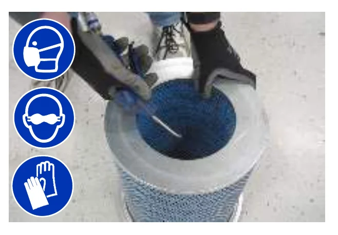
Gloved hands blowing compressed air with a nozzle through the center of the dust filter standing on a floor, with blue symbols for dust mask, eye protection and gloves at left

CLEANING THE CYCLONE ASSEMBLY (SN 006501 − )

In short Clean the cyclones and filter housing after every 100 hours of operation. Open the cyclone cover access port to empty dust and debris from the cyclone cover.
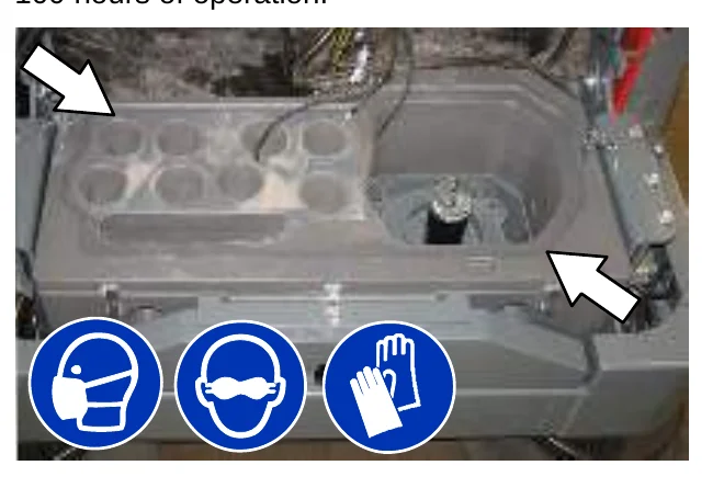
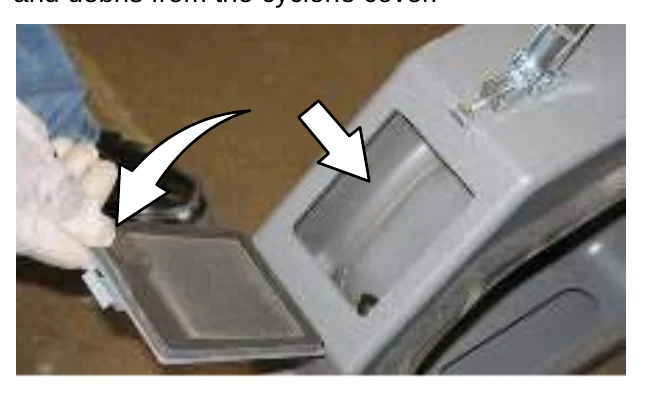
FOR SAFETY: Before leaving or servicing machine, stop on level surface, set parking brake, turn off machine, and remove key.

Clean the cyclones and filter housing after every 100 hours of operation.

Open cyclone assembly and filter housing seen from above, with arrows pointing to the cyclones and housing, and blue symbols for dust mask, eye protection and gloves along the bottom

Open the cyclone cover access port to empty dust and debris from the cyclone cover.

Cyclone cover access port opened by a gloved hand, with a curved arrow showing the door swinging open and a straight arrow pointing into the port
Source: Tennant S30 Diesel Operator Manual 9004087 Rev. 09 (4-2015), page 53, used with permission. SES ref PF-65YY-Y362‌‌​⁠‍⁠​​⁠⁠‍‌‌‍‍‌⁠‍‌​​​​​​⁠‌‌​​​‌​⁠​​⁠‍‍‍‌‌‌​‌‍​‍‌⁠‍‍‍​⁠‌‍​‌‌
S30 Diesel 9004087 (Rev. 09 (4-2015))Page 53 of 74
MAINTENANCE

MAINTENANCE

MAIN BRUSH

In short The main brush should be checked daily for wear or damage and cleared of any string or wire. Rotate it end-for-end after every 50 hours of operation and replace it when it no longer cleans effectively. The replacement steps begin with raising the brush head, opening the right side access door and removing the brush idler plate.‌‌​⁠‍⁠​​⁠⁠‍‌‌‍‍‌⁠‍‌​​​​​​⁠‌‍​​​‌​⁠​​⁠⁠‍‌‍​​‍⁠⁠‌‍‍‍‌⁠‍​⁠‍‍⁠​‌
FOR SAFETY: Before leaving or servicing machine, stop on level surface, set parking brake, turn off machine, and remove key.

Check the brush daily for wear or damage. Remove any string or wire tangled on the main brush, main brush drive hub, or main brush idler hub.‌‌​⁠‍⁠​​⁠⁠‍‌‌‍‍‌⁠‍‌​​​​​​⁠‌‍​​​‌​⁠​​⁠⁠‍‌‍​​‍⁠⁠‌‍‍‍‌⁠‍​⁠‍‍⁠​‌

Gloved hand pulling string and wire tangled in the bristles of the main brush, with a blue glove-required safety symbol at the lower left

Rotate the brush end-for-end after every 50 hours of operation, for maximum brush life and best sweeping performance. Refer to REPLACING OR ROTATING THE MAIN BRUSH.

Replace the main brush when it no longer cleans effectively.

REPLACING OR ROTATING THE MAIN BRUSH

  1. Raise the brush head.
FOR SAFETY: Before leaving or servicing machine, stop on level surface, set parking brake, turn off machine, and remove key.
  1. Open the right side main brush access door.
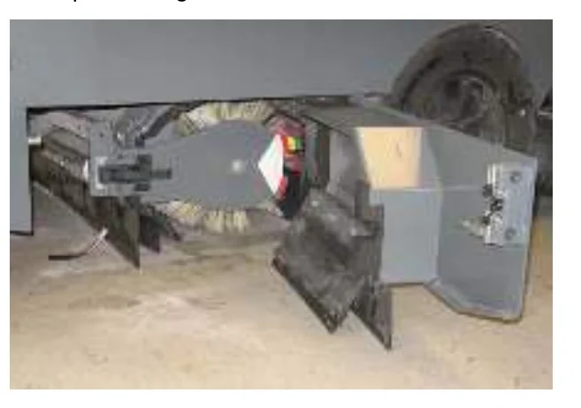
Open right side main brush access door at the side of the machine, showing the main brush and the brush idler plate
  1. Unlatch and remove the brush idler plate.
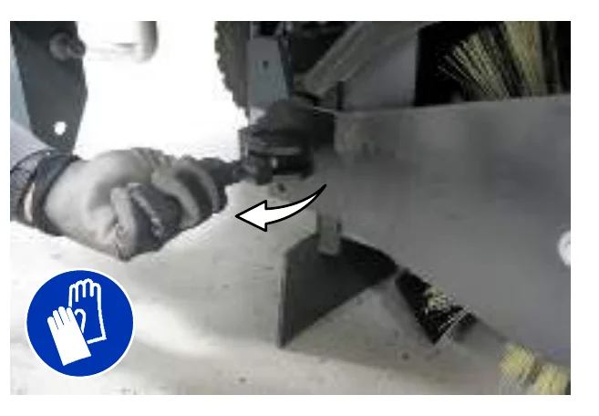
Gloved hand unlatching the brush idler plate, with an arrow showing the direction to turn the latch, and a blue glove-required safety symbol at the lower left
Source: Tennant S30 Diesel Operator Manual 9004087 Rev. 09 (4-2015), page 54, used with permission. SES ref PF-TOJT-RLXT‌‌​⁠‍⁠​​⁠⁠‍‌‌‍‍‌⁠‍‌​​​​​​⁠‌‍​​​‌​⁠​​⁠⁠‍‌‍​​‍⁠⁠‌‍‍‍‌⁠‍​⁠‍‍⁠​‌
S30 Diesel 9004087 (Rev. 09 (4-2015))Page 54 of 74
MAINTENANCE
  1. Pull the main brush from the main brush compartment.
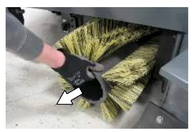
Gloved hand pulling the yellow-bristled main brush out of the main brush compartment, with a white arrow pointing in the direction the brush is pulled out
  1. Replace or rotate the main brush end-for-end.
  2. Slide the brush into the brush compartment and all the way onto the drive plug.
  3. Reinstall the brush idler plate.
Brush idler plate being reinstalled at the side of the main brush compartment, with white arrows pointing to the two mounting points and to the direction the plate slides in
  1. Close the right side main brush access door.
  2. Check and adjust the brush pattern if needed after replacing or rotating it. Refer to CHECKING THE MAIN BRUSH PATTERN.
Source: Tennant S30 Diesel Operator Manual 9004087 Rev. 09 (4-2015), page 55, used with permission. SES ref PF-SH2D-2UK6‌‌​⁠‍⁠​​⁠⁠‍‌‌‍‍‌⁠‍‌​​​​​​⁠‌⁠​​​‌​⁠​​‍‍⁠‍​‍‌⁠‍​‍‌⁠‍‌‌‌⁠‌‌‍​‍‌
S30 Diesel 9004087 (Rev. 09 (4-2015))Page 55 of 74
MAINTENANCE

CHECKING THE MAIN BRUSH PATTERN

In short Check the main brush pattern by chalking the floor, lowering the brush onto it and measuring the mark it leaves. The pattern should be the same width along the whole brush; if it is tapered, adjust the brush taper.‌‌​⁠‍⁠​​⁠⁠‍‌‌‍‍‌⁠‍‌​​​​​​⁠‍​​​​‌​⁠​​⁠​⁠‌​​‍⁠​​‌‌‍​‌‍​‍​‍‌‍‍‌
  1. Apply chalk, or a similar marking material, to a smooth and level section of the floor.
NOTE: If chalk or other material is not available, allow the brush to spin on the floor for two minutes. A polish mark will remain on the floor.
  1. Lower the main brush onto the chalked area and hold it there for 15 to 20 seconds without moving the machine.
  2. Raise the brush and drive the machine from the chalked area. The brush pattern should be 50 to 65 mm (2.0 to 2.5 in) across the entire length of the brush. Refer to ADJUSTING THE MAIN BRUSH WIDTH.
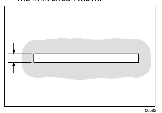
Chalked floor area with a correct brush pattern: a long rectangular brush mark of even width inside the grey chalk area, with arrows at the left marking the width of the pattern
00582
  1. If the brush pattern is tapered, see ADJUSTING THE MAIN BRUSH TAPER section of this manual.
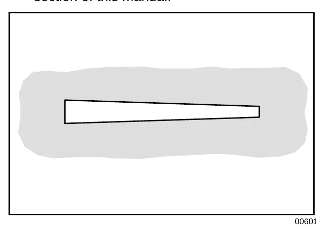
Chalked floor area with a tapered brush pattern: the brush mark is wider at the left end and narrows toward the right inside the grey chalk area
00601

ADJUSTING THE MAIN BRUSH TAPER

In short To correct a tapered brush pattern, loosen the shaft bearing bracket mounting bolts, move the bracket up or down in its slots, and retighten. Then recheck the pattern and set the adjustment knob pointer to the same color band as the brush idler plate.
FOR SAFETY: Before leaving or servicing machine, stop on level surface, set parking brake, turn off machine, and remove key.
  1. Loosen the shaft bearing bracket mounting bolts.
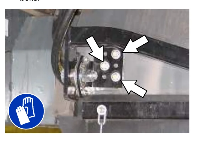
Photo of the main brush shaft bearing bracket with three white arrows pointing at the mounting bolts, and a blue glove symbol in the corner indicating gloves should be worn
  1. Move the bracket up or down in the slots and tighten the mounting bolts.
  2. Check the main brush pattern and readjust as necessary. Set the main brush adjustment knob pointer to the same color band as the brush idler plate.
Source: Tennant S30 Diesel Operator Manual 9004087 Rev. 09 (4-2015), page 56, used with permission. SES ref PF-FKMQ-MYIP‌‌​⁠‍⁠​​⁠⁠‍‌‌‍‍‌⁠‍‌​​​​​​⁠‍​​​​‌​⁠​​⁠​⁠‌​​‍⁠​​‌‌‍​‌‍​‍​‍‌‍‍‌
S30 Diesel 9004087 (Rev. 09 (4-2015))Page 56 of 74
MAINTENANCE

ADJUSTING THE MAIN BRUSH WIDTH

In short This procedure sets the main brush width by matching the bristle length to the color band on the brush idler plate. You compare the bristles to the band, move the pointer to match, and then recheck the pattern.‌‌​⁠‍⁠​​⁠⁠‍‌‌‍‍‌⁠‍‌​​​​​​⁠‍‌​​​‌​⁠​​‍‍​⁠​​⁠‌​​​⁠‍⁠​‍​⁠‍​⁠⁠‍​
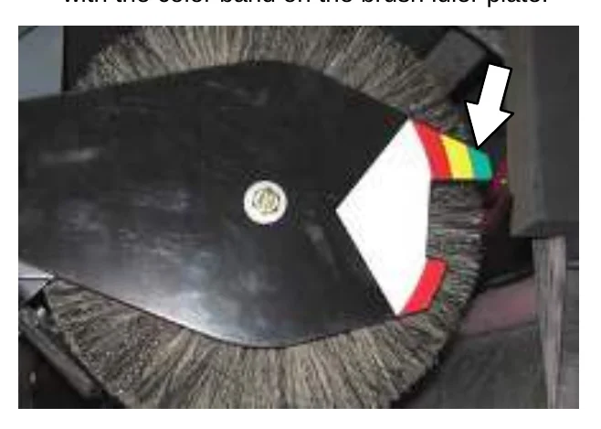
FOR SAFETY: Before leaving or servicing machine, stop on level surface, set parking brake, turn off machine, and remove key.
  1. Compare the length of the main brush bristles with the color band on the brush idler plate.
Photo of the main brush with a black idler plate; a white arrow points to the red, yellow, green color band on the plate beside the bristles
  1. Loosen the main brush adjustment knob and slide the pointer so it matches the color band on the brush idler plate. Retighten the knob.
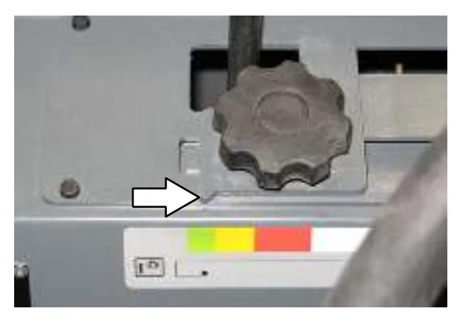
Photo of the main brush adjustment knob on the machine frame with a white arrow pointing to the pointer above the color band scale
  1. Recheck the pattern. Readjust if necessary.

SIDE BRUSH

In short Check the side brush daily for wear or damage and clear tangled string or wire. Replace it when it no longer cleans effectively by raising it, removing the retaining pin and old brush, fitting the new brush and pin, and adjusting the pattern.

Check the side brush daily for wear or damage. Remove any tangled string or wire from the side brush or side brush drive hub.‌‌​⁠‍⁠​​⁠⁠‍‌‌‍‍‌⁠‍‌​​​​​​⁠‍‌​​​‌​⁠​​‍‍​⁠​​⁠‌​​​⁠‍⁠​‍​⁠‍​⁠⁠‍​

REPLACING THE SIDE BRUSH

Replace the side brush(es) when it no longer cleans effectively.

  1. Raise the side brush.
FOR SAFETY: Before leaving or servicing machine, stop on level surface, set parking brake, turn off machine, and remove key.
  1. Remove the side brush retaining pin and then remove the side brush.
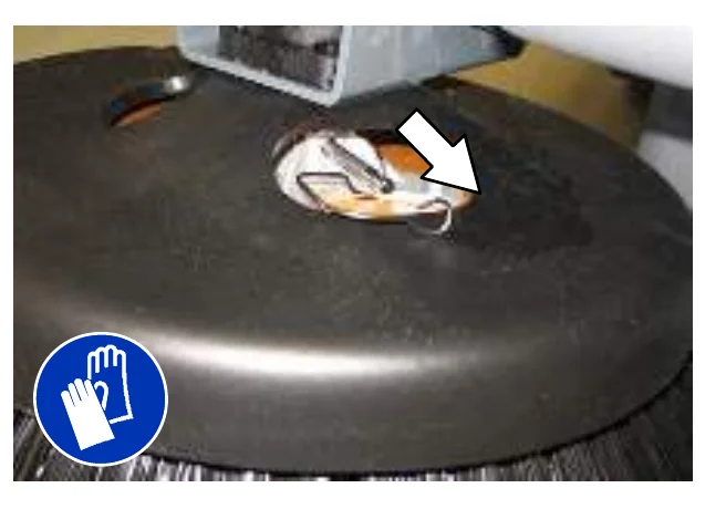
Photo of the underside of the side brush with a white arrow pointing to the retaining pin at the center, and a blue glove-required safety symbol at lower left
NOTE: Remove the drive hub and put it on the new brush if one is not installed.
  1. Slide the new side brush onto the side brush drive shaft and reinstall the retaining pin.
  2. Adjust the side brush pattern. Refer to ADJUSTING THE SIDE BRUSH PATTERN.
Source: Tennant S30 Diesel Operator Manual 9004087 Rev. 09 (4-2015), page 57, used with permission. SES ref PF-I4VN-NOPE‌‌​⁠‍⁠​​⁠⁠‍‌‌‍‍‌⁠‍‌​​​​​​⁠‍‌​​​‌​⁠​​‍‍​⁠​​⁠‌​​​⁠‍⁠​‍​⁠‍​⁠⁠‍​
S30 Diesel 9004087 (Rev. 09 (4-2015))Page 57 of 74
MAINTENANCE

ADJUSTING THE SIDE BRUSH PATTERN

In short The side brush bristles should touch the floor between 10 o'clock and 4 o'clock when the brush is moving. The adjustment knob is turned one way on the S30 and the opposite way on the S30 XP and X4 to change the pattern.‌‌​⁠‍⁠​​⁠⁠‍‌‌‍‍‌⁠‍‌​​​​​​⁠‍‍​​​‌​⁠​​⁠​​‍‍⁠​​​‌‌‍​‍‍​‍‌⁠⁠‍⁠‍‍

The side brush bristles should touch the floor between 10 o’clock and 4 o’clock when the brush is in motion.‌‌​⁠‍⁠​​⁠⁠‍‌‌‍‍‌⁠‍‌​​​​​​⁠‍‍​​​‌​⁠​​⁠​​‍‍⁠​​​‌‌‍​‍‍​‍‌⁠⁠‍⁠‍‍

Diagram of the side brush seen from above with circular arrows showing its rotation, the bristles touching the floor between 10 o'clock and 4 o'clock, next to the machine body outline
350327

S30: Turn the side brush adjustment knob counterclockwise to increase the brush pattern and clockwise to decrease the brush pattern.
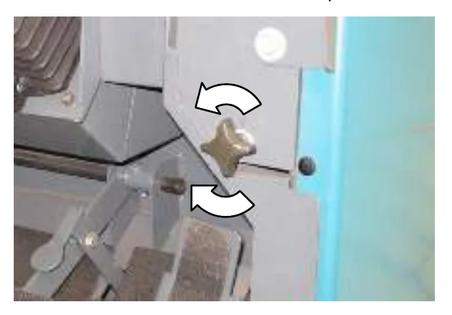
Photo of the side brush adjustment knob on the S30 with two curved arrows showing the directions the knob can be turned

S30 XP and X4: Tighten the side brush adjustment knob into the side brush bracket to the decrease brush pattern and loosen the knob to increase the brush pattern.
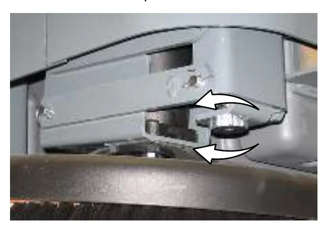
Photo of the side brush adjustment knob and bracket on the S30 XP and X4 with two curved arrows showing tightening and loosening directions

ROTATING AND REPLACING THE SIDE BRUSH GUARD

In short The side brush guard is rotated 90° every 200 hours of operation. Once all four sides have been used, the guard is replaced.

Rotate the side brush guard 90° every 200 hours of operation. Replace the brush guard after all four sides have been used.
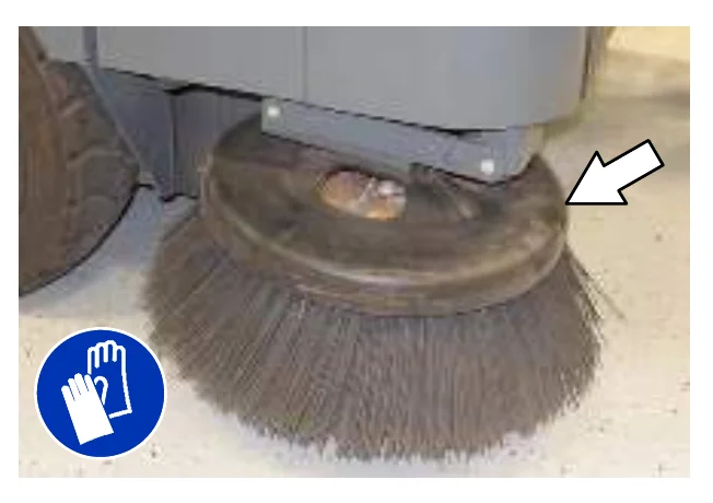
Photo of the side brush with its guard on top and a white arrow pointing to the guard; a blue symbol shows that gloves are to be worn
Source: Tennant S30 Diesel Operator Manual 9004087 Rev. 09 (4-2015), page 58, used with permission. SES ref PF-4WSX-SRZT‌‌​⁠‍⁠​​⁠⁠‍‌‌‍‍‌⁠‍‌​​​​​​⁠‍‍​​​‌​⁠​​⁠​​‍‍⁠​​​‌‌‍​‍‍​‍‌⁠⁠‍⁠‍‍
S30 Diesel 9004087 (Rev. 09 (4-2015))Page 58 of 74
MAINTENANCE

SKIRTS AND FLAPS

In short This section covers the daily check of the hopper skirts, brush door skirts, rear skirts and recirculation flap for wear or damage. The brush door and rear skirts must also clear the floor by the stated amount, with the rear tire properly inflated.‌‌​⁠‍⁠​​⁠⁠‍‌‌‍‍‌⁠‍‌​​​​​​⁠‍⁠​​​‌​⁠​​⁠‍‍⁠​‍⁠⁠‍‍‍‍​‍​​​​⁠‍‌⁠⁠​
FOR SAFETY: Before leaving or servicing machine, stop on level surface, set parking brake, turn off machine, and remove key.

HOPPER SKIRTS

Check the hopper skirts for wear or damage daily. Replace the hopper skirts when they no longer touch the floor.‌‌​⁠‍⁠​​⁠⁠‍‌‌‍‍‌⁠‍‌​​​​​​⁠‍⁠​​​‌​⁠​​⁠‍‍⁠​‍⁠⁠‍‍‍‍​‍​​​​⁠‍‌⁠⁠​

Photo of the side of the machine's hopper area with three white arrows pointing to the hopper skirts: one at the top near the opening, one at the middle of the side, and one at the bottom skirt near the floor

BRUSH DOOR SKIRTS

NOTE: Be sure the rear tire is properly inflated before checking skirt clearances.

The brush door skirts should clear the floor by 3 to 6 mm (0.12 to 0.25 in). Check the skirts for wear or damage and adjustment daily.
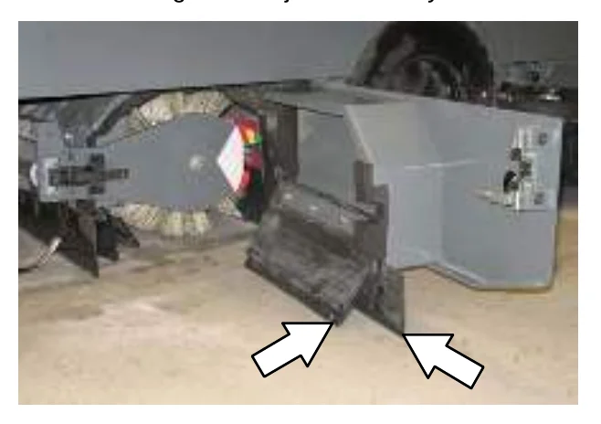
Photo of the open brush door with two white arrows pointing to the brush door skirts at the bottom edge of the door, close to the floor
NOTE: The brush door skirts have slotted holes to allow for a ground clearance adjustment. The door must be closed for proper adjustment.

REAR SKIRTS

NOTE: Be sure the rear tire is properly inflated before checking skirt clearances.

The rear brush skirt should clear the floor by 3 to 6 mm (0.12 to 0.25 in). Check the skirt for wear or damage and adjustment daily.
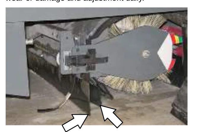
Photo of the rear of the machine showing the side brush, with two white arrows pointing to the rear brush skirt near the floor

RECIRCULATION FLAP

The recirculation flap is self-adjusting. Check the flap for wear or damage daily.
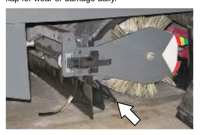
Photo of the rear of the machine showing the side brush, with one white arrow pointing to the recirculation flap
Source: Tennant S30 Diesel Operator Manual 9004087 Rev. 09 (4-2015), page 59, used with permission. SES ref PF-GCQW-HQNF‌‌​⁠‍⁠​​⁠⁠‍‌‌‍‍‌⁠‍‌​​​​​​⁠‍⁠​​​‌​⁠​​⁠‍‍⁠​‍⁠⁠‍‍‍‍​‍​​​​⁠‍‌⁠⁠​
S30 Diesel 9004087 (Rev. 09 (4-2015))Page 59 of 74
MAINTENANCE

SEALS

In short This section covers checking the brush door, hopper door, hopper inspection door and filter chamber inlet seals for wear or damage. Each is checked every 100 hours of operation, after stopping on a level surface, setting the parking brake, turning off the machine and removing the key.‌‌​⁠‍⁠​​⁠⁠‍‌‌‍‍‌⁠‍‌​​​​​​⁠⁠​​​​‌​⁠​​​‌‍‍​‌‍​⁠⁠‍​‌⁠‌​‌‌‌‍‌‍​​
FOR SAFETY: Before leaving or servicing machine, stop on level surface, set parking brake, turn off machine, and remove key.

BRUSH DOOR SEALS

Check the brush door seals for wear or damage every 100 hours of operation.‌‌​⁠‍⁠​​⁠⁠‍‌‌‍‍‌⁠‍‌​​​​​​⁠⁠​​​​‌​⁠​​​‌‍‍​‌‍​⁠⁠‍​‌⁠‌​‌‌‌‍‌‍​​

Underside view of the brush door area with the main sweeping brush, and three white arrows pointing to the brush door seals around the brush

HOPPER SEALS

Check the hopper door seals for wear or damage every 100 hours of operation.
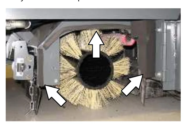
Rear view of the hopper with the brush visible, and three white arrows pointing to the hopper door seals along the top and both sides
Tilted view of the raised hopper with a red-edged door, and four white arrows pointing to the hopper door seals around its edges

HOPPER INSPECTION DOOR SEALS

Check the hopper inspection door seal for wear or damage every 100 hours of operation.
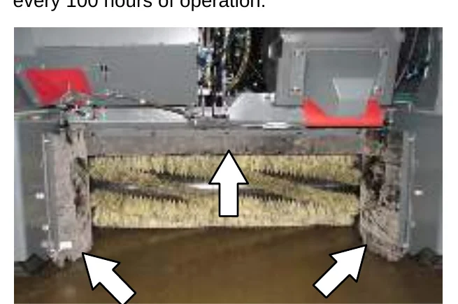
Hopper inspection door area with two white arrows pointing to the inspection door seal around the door opening

FILTER CHAMBER INLET SEAL

Check the filter chamber inlet seal for wear or damage every 100 hours of operation.
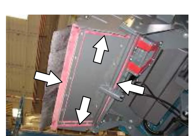
Filter chamber inlet box with a white arrow pointing to the filter chamber inlet seal, for serial numbers 000000 to 006500
(SN 000000 − 006500)
Filter chamber inlet opening with a white arrow pointing to the inlet seal, for serial number 006501 and up
(SN 006501 − )
Source: Tennant S30 Diesel Operator Manual 9004087 Rev. 09 (4-2015), page 60, used with permission. SES ref PF-ZH6A-4543‌‌​⁠‍⁠​​⁠⁠‍‌‌‍‍‌⁠‍‌​​​​​​⁠⁠​​​​‌​⁠​​​‌‍‍​‌‍​⁠⁠‍​‌⁠‌​‌‌‌‍‌‍​​
S30 Diesel 9004087 (Rev. 09 (4-2015))Page 60 of 74
MAINTENANCE

CYCLONIC PRE−FILTER SEALS

Check the cyclonic pre−filter seals for wear or damage every 100 hours of operation.‌‌​⁠‍⁠​​⁠⁠‍‌‌‍‍‌⁠‍‌​​​​​​⁠⁠‌​​​‌​⁠​​‌​​⁠​⁠​‍‍​⁠​‌​‍‍​‍‌‌⁠⁠⁠​

Cyclonic pre-filter assembly for serial numbers 000000 to 006500, with two arrows pointing to the seals along the two openings
(SN 000000 − 006500)
Cyclonic pre-filter assembly for serial numbers from 006501, with two arrows pointing to the seals at the two openings
(SN 006501 − )

DUST RETURN SEALS (SN 000000 − 006500)

Check the dust return seals for wear or damage every 100 hours of operation.
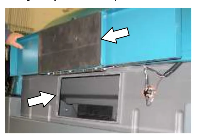
Dust return area with an arrow pointing to the red dust return seal at the bottom of the grey housing
Red dust return seal around a bracket opening on the grey panel, with an arrow pointing to the seal

DUST FILTER SEALS (SN 000000 − 006500)

Check the dust filter seals for wear or damage every 100 hours of operation.
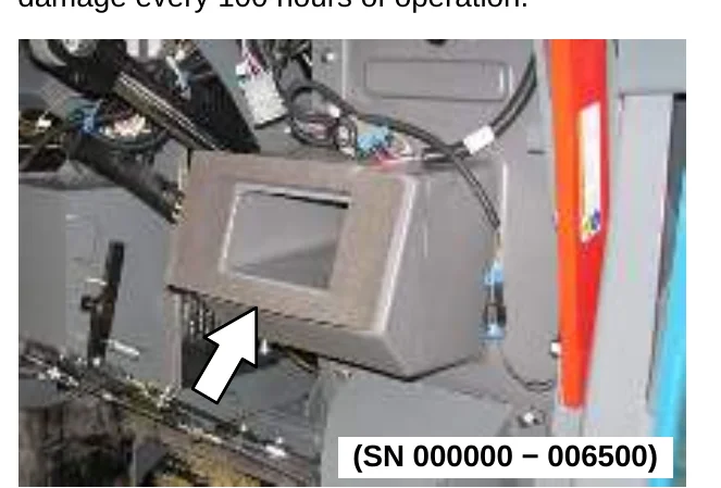
Dust filter housing seen from above with two arrows pointing to the seals around the round filter opening

VACUUM WAND DOOR SEALS (OPTION)

Check the vacuum wand door seal for wear or damage every 100 hours of operation.
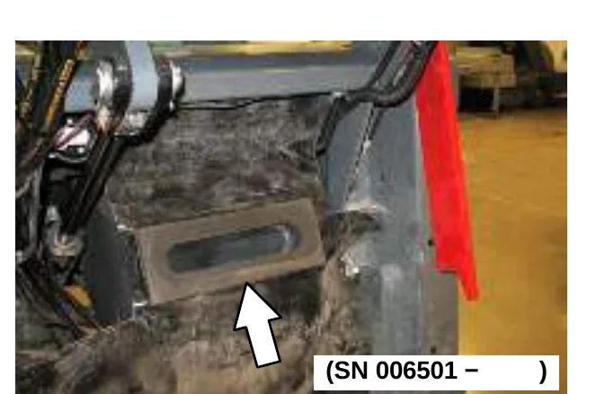
Source: Tennant S30 Diesel Operator Manual 9004087 Rev. 09 (4-2015), page 61, used with permission. SES ref PF-2TKT-A7QE‌‌​⁠‍⁠​​⁠⁠‍‌‌‍‍‌⁠‍‌​​​​​​⁠⁠‌​​​‌​⁠​​‌​​⁠​⁠​‍‍​⁠​‌​‍‍​‍‌‌⁠⁠⁠​
S30 Diesel 9004087 (Rev. 09 (4-2015))Page 61 of 74
MAINTENANCE

CYCLONIC DUST TRAY SEALS (SN 006501 − )

In short The cyclone dust tray seals are checked for wear, damage and debris buildup every 100 hours of operation. The cyclone assembly does not need to be removed to check or clean them.‌‌​⁠‍⁠​​⁠⁠‍‌‌‍‍‌⁠‍‌​​​​​​⁠⁠‍​​​‌​⁠​​​‍‌⁠⁠⁠‌‍‍⁠‍​‍⁠​⁠⁠‌​‍​‌​​

Check the cyclone dust tray seals for wear, damage, and debris buildup every 100 hours of operation.‌‌​⁠‍⁠​​⁠⁠‍‌‌‍‍‌⁠‍‌​​​​​​⁠⁠‍​​​‌​⁠​​​‍‌⁠⁠⁠‌‍‍⁠‍​‍⁠​⁠⁠‌​‍​‌​​

NOTE: It is not necessary to remove the cyclone assembly from the machine to check / clean the seals.
View of the underside of the cyclone dust tray with two arrows pointing to the tray seals along its edge
A hand pulling at the dust tray seal strip along the edge of the tray to check it

CYCLONE PERMA−FILTER (SN 006501 − )

In short Clean heavy or wet dust and excess debris from the cyclone perma-filter as needed, and check it for damage every 100 hours of operation.
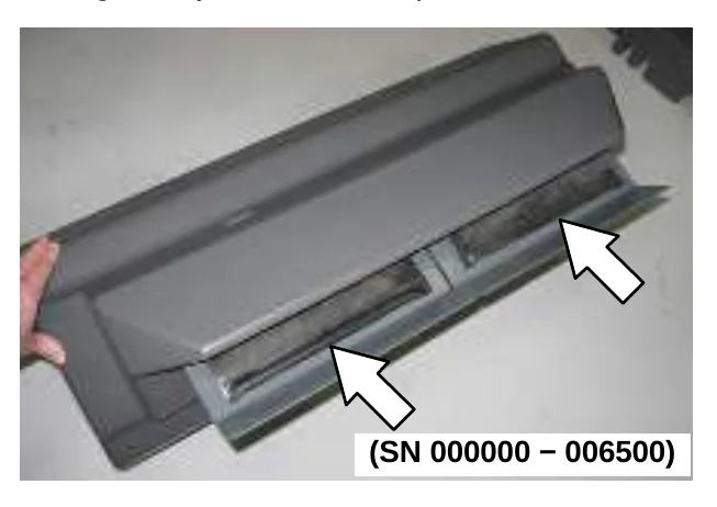
Clean heavy or wet dust and excess debris from the cyclone perma−filter as necessary. Check the cyclone perma−filter for damage every 100 hours of operation.
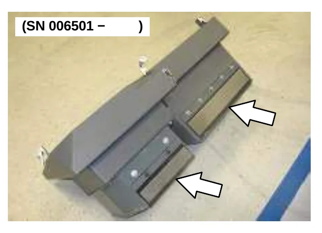
Cyclone perma-filter panel on the machine with an arrow pointing to the filter area

CYCLONE COVER SEALS (SN 006501 − )

In short The cyclone cover seals are checked for wear or damage every 100 hours of operation, and dust and debris are cleaned from the cyclones as necessary.

Check the cyclone cover seals for wear or damage every 100 hours of operation. Clean dust and debris from the cyclones as necessary.
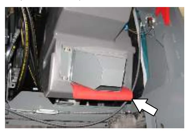
Cyclone cover seen from above with three arrows pointing to the seals around the cyclone openings

CYCLONE COVER ACCESS PORT SEAL (SN 006501 − )

In short The cyclone cover access port seal is checked for wear or damage every 100 hours of operation, and cleaned of dust and debris as necessary.

Check the cyclone cover access port seal for wear or damage every 100 hours of operation. Clean dust and debris from the seal as necessary.
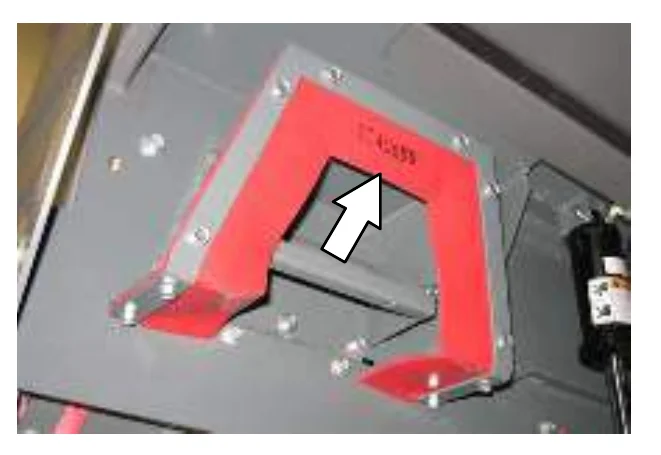
Gloved hand holding open the cyclone cover access port with an arrow pointing to the port seal

HOPPER DUST FILTER COVER SEAL (SN 006501 − )

In short The hopper dust filter cover seal is checked for wear or damage every 100 hours of operation, and cleaned of dust and debris as necessary.

Check the hopper dust filter cover seal for wear or damage every 100 hours of operation. Clean dust and debris from the seal as necessary.
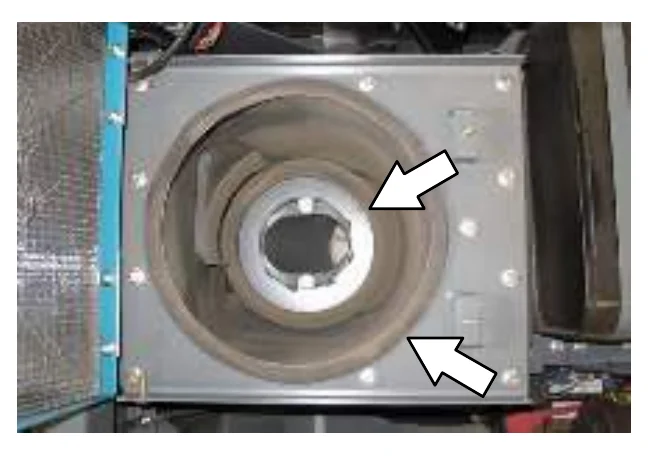
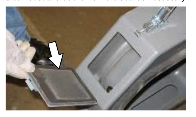
Hopper dust filter cover with an arrow pointing to the cover seal
Source: Tennant S30 Diesel Operator Manual 9004087 Rev. 09 (4-2015), page 62, used with permission. SES ref PF-YWC2-EU7S‌‌​⁠‍⁠​​⁠⁠‍‌‌‍‍‌⁠‍‌​​​​​​⁠⁠‍​​​‌​⁠​​​‍‌⁠⁠⁠‌‍‍⁠‍​‍⁠​⁠⁠‌​‍​‌​​
S30 Diesel 9004087 (Rev. 09 (4-2015))Page 62 of 74
MAINTENANCE

BRAKES AND TIRES

In short This section covers checking the brake adjustment every 200 hours, checking rear tire pressure every 100 hours, and torquing the rear wheel nuts in the shown pattern.‌‌​⁠‍⁠​​⁠⁠‍‌‌‍‍‌⁠‍‌​​​​​​⁠⁠⁠​​​‌​⁠​​⁠‌‍‌‍‌⁠⁠⁠​‍​‍⁠‌​⁠‌‍‍‍⁠​‍

BRAKES

Check the brake adjustment after every 200 hours of operation.‌‌​⁠‍⁠​​⁠⁠‍‌‌‍‍‌⁠‍‌​​​​​​⁠⁠⁠​​​‌​⁠​​⁠‌‍‌‍‌⁠⁠⁠​‍​‍⁠‌​⁠‌‍‍‍⁠​‍

To check the brake adjustment, measure the distance from the stationary brake pedal to the point where there is resistance in the pedal movement. The distance must be 19 to 25 mm (0.75 to 1.0 in). Adjust the brakes if required.
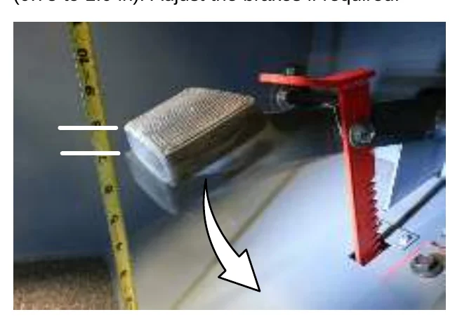
Photo of the brake pedal with a tape measure alongside and parallel lines showing the pedal travel, with an arrow pointing down along the pedal movement

TIRES

The standard front tires are solid. The standard rear tire is pneumatic.

Check the rear tire pressure every 100 hours of operation. The proper air pressure is 790 ± 35 kPa (115 ± 5 psi).

REAR WHEEL

Torque the rear wheel nuts twice in the pattern shown to 122 to 149 Nm (90 to 110 ft lb) after the first 50 hours of operation, and then after every 800 hours.
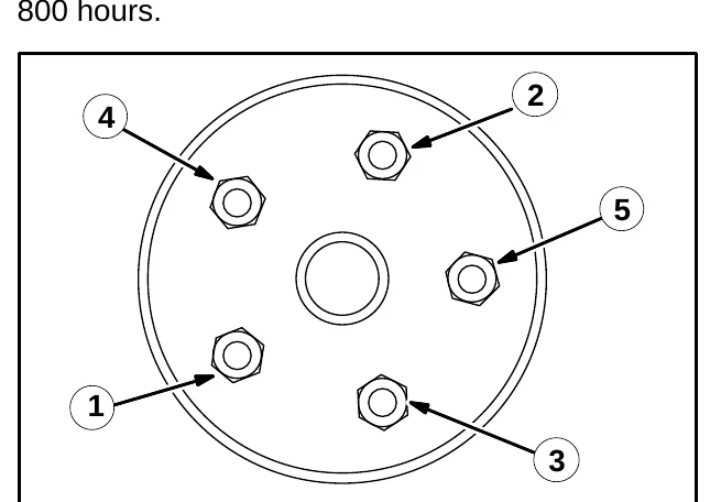
Rear wheel with five lug nuts numbered 1 to 5 by arrows, showing the tightening pattern

PROPELLING MOTOR

In short The propelling motor shaft nut must be torqued every 800 hours of operation, to a lower value if lubricated and a higher value if dry.

Torque the shaft nut to 508 Nm (375 ft lb) lubricated, 644 Nm (475 ft lb) dry, after every 800 hours of operation.
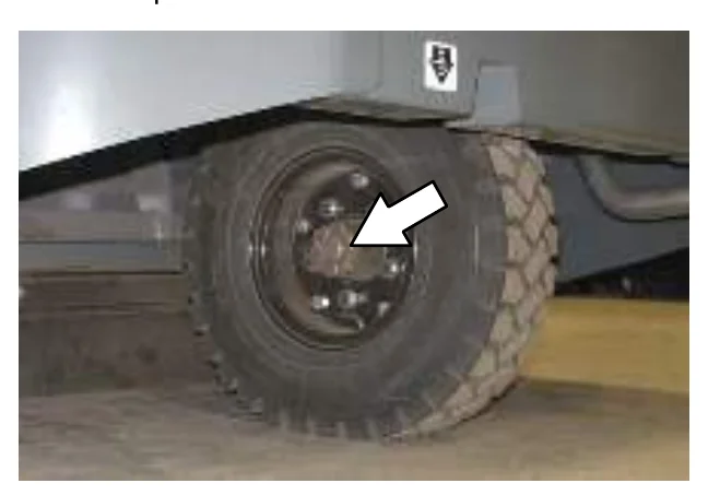
Photo of the machine's wheel with an arrow pointing to the propelling motor shaft nut at the wheel center
Source: Tennant S30 Diesel Operator Manual 9004087 Rev. 09 (4-2015), page 63, used with permission. SES ref PF-4DNK-FZ72‌‌​⁠‍⁠​​⁠⁠‍‌‌‍‍‌⁠‍‌​​​​​​⁠⁠⁠​​​‌​⁠​​⁠‌‍‌‍‌⁠⁠⁠​‍​‍⁠‌​⁠‌‍‍‍⁠​‍
S30 Diesel 9004087 (Rev. 09 (4-2015))Page 63 of 74
MAINTENANCE

PUSHING, TOWING, AND TRANSPORTING THE MACHINE

In short A disabled machine can be pushed or towed only a very short distance, and only after the bypass valve on the propelling pump has been turned. The page also begins the steps for loading the machine onto a truck or trailer.‌‌​⁠‍⁠​​⁠⁠‍‌‌‍‍‌⁠‍‌​​​​​‌​​​​​​‌​⁠​​‌‍‌⁠​‌​⁠‍⁠‍‌⁠‍‌‍‌⁠⁠‌⁠‍⁠⁠

PUSHING OR TOWING THE MACHINE

If the machine becomes disabled, it can be pushed from the front or rear, but only towed from the rear.‌‌​⁠‍⁠​​⁠⁠‍‌‌‍‍‌⁠‍‌​​​​​‌​​​​​​‌​⁠​​‌‍‌⁠​‌​⁠‍⁠‍‌⁠‍‌‍‌⁠⁠‌⁠‍⁠⁠

Use the bypass valve to prevent damaging the hydraulic system when pushing or towing the machine. This valve allows a disabled machine to be moved for a very short distance and at a speed to not exceed 1.6 kp/h (1 mph). The machine is NOT intended to be pushed or towed a long distance or at a high speed.

ATTENTION! Do not push or tow machine for a long distance or damage may occur to the propelling system.

Turn the bypass valve located on the bottom of the propelling pump 90° (either direction) from the normal position before pushing or towing the machine. Return the bypass valve to the normal position when finished pushing or towing the machine. Do Not use the bypass valve during normal machine operation.
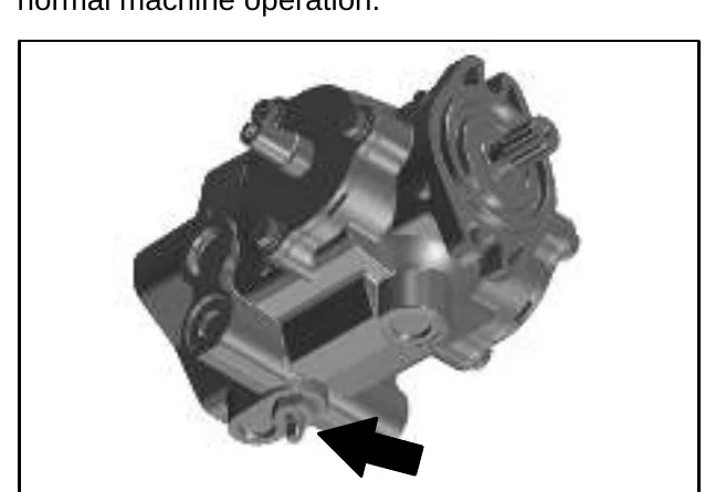
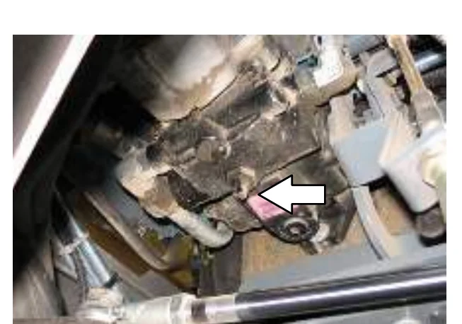
Drawing of the propelling pump with a black arrow pointing to the bypass valve on its bottom
Photo looking up at the underside of the machine with a white arrow pointing to the bypass valve on the propelling pump

TRANSPORTING THE MACHINE

  1. Raise the brushes. If necessary, slightly raise the hopper for additional ramp clearance.
FOR SAFETY: When loading machine onto truck or trailer, empty debris hopper before loading machine.
  1. Position the front of the machine at the loading edge of the truck or trailer.
FOR SAFETY: When loading machine onto truck or trailer, use winch. Do not drive the machine onto the truck or trailer unless the loading surface is horizontal AND is 380 mm (15 in) or less from the ground.
  1. If the loading surface is horizontal and 380 mm (15 in) or less from the ground, drive the machine onto the truck or trailer.
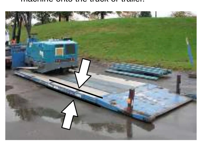
Photo of the machine on a flat trailer at ground level, with white arrows showing the horizontal loading surface and its height from the ground
  1. To winch the machine onto the truck or trailer, attach the winching chains to the holes in the right and left lower corners in front of the machine.
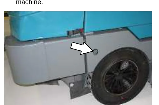
Photo of the lower front corner of the machine with a white arrow pointing to the hole for the winching chain
Source: Tennant S30 Diesel Operator Manual 9004087 Rev. 09 (4-2015), page 64, used with permission. SES ref PF-U2KI-MM35‌‌​⁠‍⁠​​⁠⁠‍‌‌‍‍‌⁠‍‌​​​​​‌​​​​​​‌​⁠​​‌‍‌⁠​‌​⁠‍⁠‍‌⁠‍‌‍‌⁠⁠‌⁠‍⁠⁠
S30 Diesel 9004087 (Rev. 09 (4-2015))Page 64 of 74
MAINTENANCE

MAINTENANCE

  1. Position the machine as close to the front of the trailer or truck as possible.
  2. Set the parking brake and place a block behind each wheel to prevent the machine from rolling.
  3. Lower the brushes and hopper (if hopper was raised).
  4. Connect the tie−down straps to the holes in the right and left lower corners in front of the machine and the holes in the rear jacking brackets behind the rear tires.
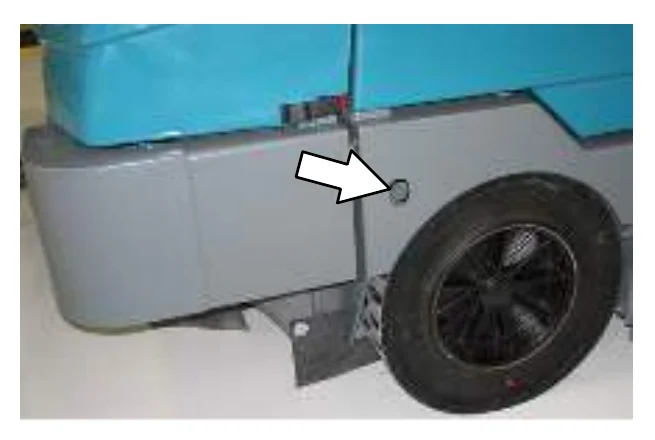
Front right lower corner of the machine beside the front wheel, with an arrow pointing to the tie-down hole
Rear of the machine with an arrow pointing to the rear jacking bracket hole behind the rear tire where a tie-down strap connects
  1. Route the tie−downs to the opposite ends of the machine and hook them to the brackets on the floor of the trailer or truck. Tighten the tie−down straps.
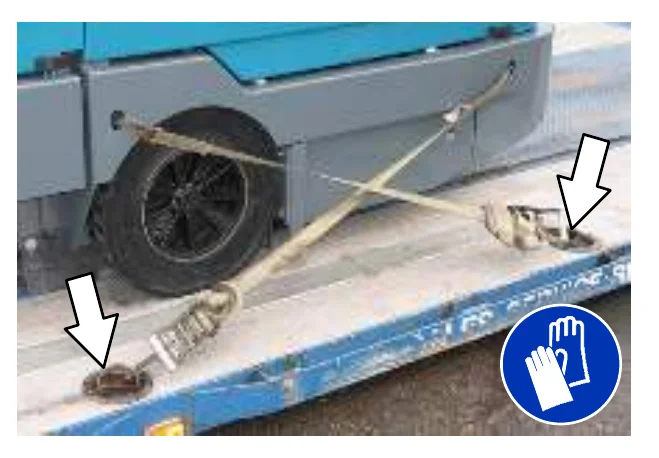
NOTE: It may be necessary to install tie-down brackets to the floor of the trailer or truck.
Machine on a trailer secured with crossed tie-down straps hooked to brackets on the trailer floor, with arrows pointing to the hook points and a blue glove-required symbol
FOR SAFETY: When unloading machine off truck or trailer, use winch. Do not drive the machine off the truck or trailer unless the loading surface is horizontal AND 380 mm (15 in) or less from the ground.
  1. If the loading surface is horizontal AND is 380 mm (15 in) or less from the ground, drive the machine off the truck or trailer.
Source: Tennant S30 Diesel Operator Manual 9004087 Rev. 09 (4-2015), page 65, used with permission. SES ref PF-WPJM-DFDP‌‌​⁠‍⁠​​⁠⁠‍‌‌‍‍‌⁠‍‌​​​​​‌​​‌​​​‌​⁠​​​‌‌‍​​⁠‌‍​‍‍⁠‌‍‍​​​⁠​⁠⁠⁠
S30 Diesel 9004087 (Rev. 09 (4-2015))Page 65 of 74
MAINTENANCE

MACHINE JACKING

In short Empty the hopper and jack the machine up only at the designated front and rear locations, using a hoist or jack that can support the machine's weight plus jack stands. Block the tires and secure the machine before servicing.‌‌​⁠‍⁠​​⁠⁠‍‌‌‍‍‌⁠‍‌​​​​​‌​​‍​​​‌​⁠​​‌⁠‌‍‌‍‍​​⁠‍‌‌‌⁠​​​‍‍⁠‍‌​

Empty the hopper before jacking up the machine. Jack up the machine at the designated locations. Use a hoist or jack capable of supporting the weight of the machine. Use jack stands to support the machine.‌‌​⁠‍⁠​​⁠⁠‍‌‌‍‍‌⁠‍‌​​​​​‌​​‍​​​‌​⁠​​‌⁠‌‍‌‍‍​​⁠‍‌‌‌⁠​​​‍‍⁠‍‌​

FOR SAFETY: Before leaving or servicing machine, stop on level surface, set parking brake, turn off machine, and remove key.
FOR SAFETY: When servicing machine, block machine tires before jacking machine up. Use a hoist or jack that will support the weight of the machine. Jack machine up at designated locations only. Support machine with jack stands.

Rear jacking locations are located directly behind the rear tire on each side of the machine.
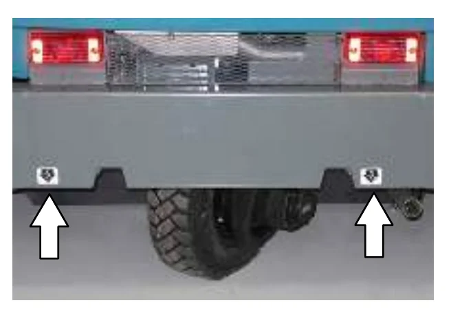
Rear of the machine showing the two rear jacking locations, each marked with a jacking label and a white arrow pointing up, located behind the rear tire on each side

Front jacking locations are located on the frame directly in front of the front tire.
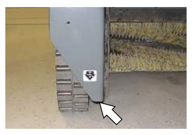
Front corner of the machine frame directly in front of the front tire, with a white arrow pointing to the front jacking location marked by a jacking label

STORAGE INFORMATION

In short Before storing the machine for extended periods, park it indoors in a cool, dry area. Remove the battery, or charge it every three months.

Batteries and chargers: make sure your charger is compatible with your batteries, and set its charging algorithm to your battery pack before you use it.

The following steps should be taken prior to storing the machine for extended periods.

  1. Park the machine in a cool, dry area. Do not expose the machine to rain or snow. Store indoors.
  2. Remove the battery, or charge battery every three months.
Source: Tennant S30 Diesel Operator Manual 9004087 Rev. 09 (4-2015), page 66, used with permission. SES ref PF-FZIX-Z5Q7‌‌​⁠‍⁠​​⁠⁠‍‌‌‍‍‌⁠‍‌​​​​​‌​​‍​​​‌​⁠​​‌⁠‌‍‌‍‍​​⁠‍‌‌‌⁠​​​‍‍⁠‍‌​
S30 Diesel 9004087 (Rev. 09 (4-2015))Page 66 of 74
SPECIFICATIONS

SPECIFICATIONS

GENERAL MACHINE DIMENSIONS/CAPACITIES

In short This section lists the machine's dimensions, capacities, weights, sound and vibration values, and performance limits such as turning radius, travel speeds and ramp inclines. Use the figures for the model you have (S30, S30 XP or S30 X4).‌‌​⁠‍⁠​​⁠⁠‍‌‌‍‍‌⁠‍‌​​​​​‌​​⁠​​​‌​⁠​​‌‌​⁠‍‌​‍‌⁠‍⁠‌​​‍‍‍‌​‍⁠​‍
ItemDimension/capacity
Length2360 mm (93 in)
Height1475 mm (58 in)
Height (with overhead guard or cab machines with AC)2095 mm (82.5 in)
Width/frame1590 mm (62.5 in)
Wheel base1226 mm (48.25 in)
Track1426 mm (56.125 in)
Cleaning path width (Single side brush)1590 mm (62.5 in)
Cleaning path width (Dual side brushes)2030 mm (80 in)
Main brush diameter356 mm (14 in)
Side brush diameter660 mm (26 in)
Debris hopper volume capacity (Plastic and Steel)395 L (14 ft3)
Debris hopper weight capacity (Plastic)490 kg (1080 lbs)
Debris hopper weight capacity (Steel)545 kg (1200 lbs)
Dump height (variable to)1525 mm (60 in)
Minimum ceiling dump height2500 mm (98 in)
Weight − empty1595 Kg (3520 lbs)
GVWR2585 Kg (5700 lbs)
Transport ground clearance100 mm (4 in)
Protection GradeIPX3
Values determined as per EN 60335−2−72Measure
Sound pressure level LpA83 dB(A)
Sound pressure uncertainty KpA3 dB(A)
Sound power level LWA + Uncertainty KWA100 dB(A)
Vibration − Hand−arm<2.5 m/s2
Vibration − Whole body<0.5 m/s2

GENERAL MACHINE PERFORMANCE

ItemMeasure
Minimum aisle turn (S30 and S30 XP)2870 mm (113 in)
Minimum aisle turn (S30 X4)5000 mm (196.75 in)
Travel speed forward (maximum) (S30 and S30 XP)13.0 Km/h (8 mph)
Travel speed forward (maximum) (S30 X4)24.0 Km/h (15 mph)
Travel speed reverse (maximum)5.0 Km/h (3 mph)
Maximum ramp incline for loading − Empty (S30 and S30 XP)25%
Maximum ramp incline for loading − Empty (S30 X4)16%
Maximum ramp incline for sweeping (All Models)14%
Maximum ramp incline for transporting (GVWR) (S30 and S30 XP)17%
Maximum ramp incline for transporting (GVWR) (S30 X4)10.5%
Source: Tennant S30 Diesel Operator Manual 9004087 Rev. 09 (4-2015), page 67, used with permission. SES ref PF-24QT-3RPT‌‌​⁠‍⁠​​⁠⁠‍‌‌‍‍‌⁠‍‌​​​​​‌​​⁠​​​‌​⁠​​‌‌​⁠‍‌​‍‌⁠‍⁠‌​​‍‍‍‌​‍⁠​‍
S30 Diesel 9004087 (Rev. 09 (4-2015))Page 67 of 74
SPECIFICATIONS

SPECIFICATIONS

In short This page lists the machine's hydraulic fluid capacities and grades, steering type, engine data, braking system and tire sizes. Use it to check the correct values for each system.‌‌​⁠‍⁠​​⁠⁠‍‌‌‍‍‌⁠‍‌​​​​​‌​‌​​​​‌​⁠​​‍‌‍⁠⁠​‍‍‌⁠​​‌‍⁠​​‍‌⁠‌‍‍⁠

HYDRAULIC SYSTEM

SystemCapacityISO Grade Viscosity IndexAmbient Air Temperature Ranges
Hydraulic reservoir38 L (10 gal)ISO 100 VI 126 or higher19° C (65° F) or higher
Hydraulic total45 L (12 gal)ISO 68 VI 155 or higher7 to 43° C (45 to 110° F)
ISO 32 VI 163 or higher16° C (60° F) or lower

STEERING

TypePower source
Rear wheel, hydraulic cylinderHydraulic accessory pump

POWER TYPE

EngineTypeIgnitionCycleAspirationCylindersBoreStroke
Kubota V1505−BPistonDiesel4Natural478 mm (3.07 in)78.4 mm (3.08 in)
DisplacementNet power, governedNet power, maximum
1500 cc (91.4 cu in)24.6 kw (34 hp) @ 2400 rpm27.2 kw (37.5 hp) @ 3000 rpm
FuelCooling systemElectrical system
Diesel
Fuel tank: 42 L (11.2 gal)
low sulfer fuel content less than 500ppm only
*5% maximum biodiesel
Water/ethylene glycol antifreeze12 V nominal
Total: 7.5 L (2 gal)75 A alternator
Radiator: 3.8 L (1 gal)
Idle speed, no load(Fast) governed speed, under loadEngine lubricating oil without filter
1350 ± 50 rpm2000 ± 50 rpm
2400 ± 50 rpm
6 L (6.35 qt) API diesel classification CF or better

BRAKING SYSTEM

TypeOperation
Service brakesMechanical drum brakes (2), one per front wheel, cable actuated
Parking brakeUtilize service brakes, cable actuated

TIRES

LocationTypeSize
Front (2)Solid127 mm x 535 mm (5 in x 21 in)
Rear (1)
(S30 and S30 XP)
Pneumatic115 mm x 470 mm (4.5 in x 18.5 in)
Rear (2) (S30 X4)Foam Fill115 mm x 410 mm (4.5 in x 16 in)
Source: Tennant S30 Diesel Operator Manual 9004087 Rev. 09 (4-2015), page 68, used with permission. SES ref PF-LZKP-CB7L‌‌​⁠‍⁠​​⁠⁠‍‌‌‍‍‌⁠‍‌​​​​​‌​‌​​​​‌​⁠​​‍‌‍⁠⁠​‍‍‌⁠​​‌‍⁠​​‍‌⁠‌‍‍⁠
S30 Diesel 9004087 (Rev. 09 (4-2015))Page 68 of 74
SPECIFICATIONS

SPECIFICATIONS

MACHINE DIMENSIONS

In short This page gives the overall dimensions of the machine in millimeters and inches, for the version with the overhead guard and the version with the cab. Use the drawings to check height, length, width, wheel base and track.‌‌​⁠‍⁠​​⁠⁠‍‌‌‍‍‌⁠‍‌​​​​​‌​‌‌​​​‌​⁠​​⁠​​‌‌​⁠‍⁠⁠​​​⁠‌‍⁠​‍⁠⁠​⁠⁠
Top, side and rear views of the machine with the overhead guard, with dimension arrows: overall height 2095 mm (82.5 in), height to the seat area 1475 mm (58 in), wheel base 1226 mm (48.25 in), overall length 2360 mm (93 in), track 1426 mm (56.125 in) and overall width 1590 mm (62.5 in)
Top, side and rear views of the machine with the cab, with dimension arrows: overall height 2095 mm (82.5 in), wheel base 1226 mm (48.25 in), overall length 2360 mm (93 in), track 1426 mm (56.125 in) and overall width 1590 mm (62.5 in)
354726
Source: Tennant S30 Diesel Operator Manual 9004087 Rev. 09 (4-2015), page 69, used with permission. SES ref PF-GXIT-5MVH‌‌​⁠‍⁠​​⁠⁠‍‌‌‍‍‌⁠‍‌​​​​​‌​‌‌​​​‌​⁠​​⁠​​‌‌​⁠‍⁠⁠​​​⁠‌‍⁠​‍⁠⁠​⁠⁠
S30 Diesel 9004087 (Rev. 09 (4-2015))Page 69 of 74
INDEX

INDEX

In short This page lists topics beginning with the number 1 and the letters A through E, each followed by the manual page numbers where it is covered. Use it to find controls, adjustments, filters, seals, brakes and engine service topics.‌‌​⁠‍⁠​​⁠⁠‍‌‌‍‍‌⁠‍‌​​​​​‌​‌‍​​​‌​⁠​​​⁠‍​​⁠‍‌​⁠‌​​‌⁠‌‍‍‌‍‌​‍‌

1

1−STEP Sweep button, 14, 23‌‌​⁠‍⁠​​⁠⁠‍‌‌‍‍‌⁠‍‌​​​​​‌​‌‍​​​‌​⁠​​​⁠‍​​⁠‍‌​⁠‌​​‌⁠‌‍‍‌‍‌​‍‌

A

Access door, hopper, 16

Adjust deluxe suspension seat, 17

Adjust operator seat, 17

Adjust steering column, 11

Adjusting the Main Brush Taper, 54

Adjusting the Main Brush Width, 55

Adjusting the Side Brush Pattern, 56

Air Filter, 44

  • Replace the safety filter element, 44

Air filter indicator, 44

  • Reset, 45

Alarms, 27, 28

  • Fault Indicators (S30 XP and X4), 28
  • Fault Indicators (S30), 27

B

Battery, 46

Blower Wand (Option), 30

Brake pedal, 11

Brakes, 61

  • System specifications, 66

Brakes and Tires, 61

  • Brakes, 61
  • Rear Wheel, 61
  • Tires, 61

Brush Door Seals, 58

Brush Door Skirts, 57

Brush Information, 18

Buttons

  • 1−STEP Sweep button, 14, 23
  • Contrast control button, 14
  • Engine Speed Button, 13
  • Filter shaker button, 15
  • Hopper door close button, 24
  • Hopper lower button, 25
  • Hopper raise button, 24
  • Supervisor Control Buttons, 13
  • Vacuum fan button, 14, 30

Buttons, Controls and Instruments, 9, 13

Bypass valve, 62

C

Cab Fuses, 48

Cab light (Option), 31

Cab light switch, 31

Capacities, 65

Checking the Main Brush Pattern, 54

Cleaning the Cyclone Assembly, 51

Cleaning the Dust Filter, 51

Contrast control button, 14

Controls and Instruments, 8, 9

  • Touch Panel, 9

Cooling System, 42

  • Check the coolant level in the reservoir, 42
  • Flush the radiator and the cooling system, 42

Cyclone Assembly, Cleaning, 51

Cyclone cover access port seal, 60

Cyclone cover seals, 60

Cyclone perma−filter, 60

Cyclonic Dust Tray Seals, 60

Cyclonic Pre−filter Seals, 59

D

Dash fault indicators, 29

Dimensions, 65

Directional pedal, 11

Disengaging hopper support bar, 26

Dust Filter, 49, 50

  • Removing the Dust Filter, 49, 50
  • Replacing the Dust Filter, 49, 50

Dust Filter Seals, 59

Dust Return Seals, 59

E

Emptying the hopper, 24

Engaging hopper support bar, 25

Engine, 42

  • Air Filter, 44
  • Air filter indicator, 44
  • Cooling System, 42
  • Engine Belt, 46
  • Fuel Filter, 45
  • Fuel Lines, 45
  • Priming the fuel system, 46
  • Specifications, 66
Source: Tennant S30 Diesel Operator Manual 9004087 Rev. 09 (4-2015), page 70, used with permission. SES ref PF-MVAY-ZFEO‌‌​⁠‍⁠​​⁠⁠‍‌‌‍‍‌⁠‍‌​​​​​‌​‌‍​​​‌​⁠​​​⁠‍​​⁠‍‌​⁠‌​​‌⁠‌‍‍‌‍‌​‍‌
S30 Diesel 9004087 (Rev. 09 (4-2015))Page 70 of 74
INDEX

INDEX

Engine air filter, Cleaning, 44
Engine Belt, 46
Engine Harness Fuses and Relays, 48
Engine Oil, 38
Engine Speed Button, 13
Engine Speed Switch, 13‌‌​⁠‍⁠​​⁠⁠‍‌‌‍‍‌⁠‍‌​​​​​‌​‌⁠​​​‌​⁠​​‍‍⁠⁠‍​‍​‌⁠‍‌⁠‍⁠​⁠‍​​​‌​‍

F

Fan knob, 31
Fault Indicators (S30 XP and X4), 28
Fault Indicators (S30), 27
Filter Chamber Inlet Seal, 58
Filter shaker button, 15
Filter shaker switch, 15
Filters, 49, 50

  • Cleaning the Dust Filter, 51
  • Cyclone perma−filter, 60
  • Diesel Fuel Filter, 45
  • Engine Air Filter, 44
  • Hydraulic Fluid Filter, 40
  • Removing the Dust Filter, 49, 50
  • Replacing the Dust Filter, 49, 50

Flaps, 57
Front jacking locations, 64
Front Wheel Bearings, 39
Fuel Filter, 45
Fuel Indicator, 12
Fuel Lines, 45
Fuses and Relays, 47

  • Cab Fuses, 48
  • Engine Harness Fuses and Relays, 48
  • Relay Panel Fuses and Relays, 47

G

General Machine Dimensions / Capacities, 65
General Machine Performance, 65
Glow Plug Light, 20

H

Headlights, 15
Heater / Air conditioner (Option), 31
Heater / Air conditioner switch, 31
Hopper access door, 16
Hopper door switch, 22, 24
Hopper dust filter cover seal, 60
Hopper Inspection Door Seals, 58
Hopper Lift Arm Pivots, 38
Hopper lower button, 25
Hopper lower switch, 25
Hopper raise button, 24
Hopper raise switch, 24
Hopper Seals, 58
Hopper Skirt, 57
Hopper support bar, 25

  • Disengaging hopper support bar, 26
  • Engaging hopper support bar, 25

Hour Meter, 13
How the Machine Works, 18
Hydraulic Cooler, 43

  • Clean the fins, 43

Hydraulic Fluid, 41
Hydraulic Hoses, 41
Hydraulic System, System specifications, 66
Hydraulics, 40

  • Check the hydraulic fluid level, 40
  • Check the hydraulic hoses, 41
  • Hydraulic Fluid, 41
  • Hydraulic Hoses, 41
  • Replace the hydraulic fluid filter, 40

I

Indicators

  • Dash fault indicators, 29
  • Fault Indicators (S30 XP and X4), 28
  • Fault Indicators (S30), 27
  • Fuel Indicator, 12
  • Glow Plug Light, 20
  • Hour Meter, 13
Source: Tennant S30 Diesel Operator Manual 9004087 Rev. 09 (4-2015), page 71, used with permission. SES ref PF-SZAX-YINO‌‌​⁠‍⁠​​⁠⁠‍‌‌‍‍‌⁠‍‌​​​​​‌​‌⁠​​​‌​⁠​​‍‍⁠⁠‍​‍​‌⁠‍‌⁠‍⁠​⁠‍​​​‌​‍
S30 Diesel 9004087 (Rev. 09 (4-2015))Page 71 of 74
INDEX

INDEX

K

  • Knobs
    • Fan knob, 31
    • Side Brush Adjustment Knob, 56
    • Temperature knob, 31

L

  • Lights
    • Operating / hazard, 15
    • Operating / hazard light, 15
  • Lubrication, 38
    • Engine Oil, 38
    • Front Wheel Bearings, 39
    • Hopper Lift Arm Pivots, 38
    • Rear Wheel Support Bearing, 38
    • Steering Cylinder Bearing, 38
    • Steering Rod End, 39
    • Steering Spindles, 39

M

  • Machine components, 7
  • Machine Dimensions, 67
  • Machine Jacking, 64
    • Front jacking locations, 64
    • Rear jacking locations, 64
  • Machine Operation, Pre-Operation Checklist, 19
  • Machine Performance
    • Aisle Turnaround Width, 65
    • Climb and Descent Angles, 65
    • Travel Speed (Maximum), 65
  • Machine Specifications, 65
  • Machine Troubleshooting, 33
  • Main Brushes, 52
    • Adjusting the Taper, 54
    • Adjusting the Width, 55
    • Checking the Main Brush Pattern, 54
    • Replacing or Rotating the Main Brushes, 52
  • Main Brushes, Adjusting the Taper, 54
  • Main Brushes, Adjusting the Width, 55
  • Main Brushes, Checking the Pattern, 54
  • Main Brushes, Replacing or Rotating, 52
  • Maintenance, 35
  • Maintenance Chart, 35

O

  • Operating / hazard lights, 15
  • Operating temperature, 21
  • Operation, 7
  • Operation of controls, 11
  • Operator seat, 17
  • Options, 30
    • Blower wand, 30
    • Cab light, 31
    • Heater / Air conditioner, 31
    • Side brush light, 15
    • Tower bumpers, 32
    • Turn Signal, 32
    • Vacuum wand, 30
    • Windshield wiper, 31

P

  • Parking brake pedal, 11
  • Pedals
    • Brake pedal, 11
    • Directional pedal, 11
    • Parking brake pedal, 11
    • Steering column tilt pedal, 11
  • Pre-Operation Checklist, 19
  • Preheat-Glow Plug Light, 20
  • Priming the fuel system, 46
  • Propelling Motor, 61
    • Torque Shaft Nut, 61
  • Pushing or Towing the Machine, 62
  • Pushing the Machine, 62
  • Pushing, Towing, and Transporting the Machine, 62
    • Pushing or Towing the Machine, 62
    • Transporting the Machine, 62

R

  • Radiator, 42
    • Check hoses and clamps, 42
    • Clean core exterior, 43
  • Rear jacking locations, 64
  • Rear Skirt, 57
  • Rear Wheel Support Bearing, 38
  • Rear Wheel, Torque, 61
Source: Tennant S30 Diesel Operator Manual 9004087 Rev. 09 (4-2015), page 72, used with permission. SES ref PF-RMHR-P7KH‌‌​⁠‍⁠​​⁠⁠‍‌‌‍‍‌⁠‍‌​​​​​‌​‍​​​​‌​⁠​​‍‍‌​​⁠‍⁠⁠⁠‌‌⁠‍⁠⁠​‍⁠⁠‌​⁠‍
S30 Diesel 9004087 (Rev. 09 (4-2015))Page 72 of 74
INDEX

INDEX

  • Recirculation Flap, 57
  • Relay Panel Fuses and Relays, 47
  • Removing the Dust Filter, 49, 50
  • Replacing or Rotating the Main Brushes, 52
  • Replacing the Dust Filter, 49, 50
  • Replacing the Side Brush, 55
  • Replacing the Side Brush Guard, 56
  • Reset air filter indicator, 45
  • Rotating the Side Brush Guard, 56

S

  • Safety
    • Instructions, 3
    • Labels, 5
  • Seals, 58
    • Brush Door Seals, 58
    • Cyclone cover access port seal, 60
    • Cyclone cover seals, 60
    • Cyclonic Dust Tray Seals, 60
    • Cyclonic Pre-filter Seals, 59
    • Dust Filter Seals, 59
    • Dust Return Seals, 59
    • Filter Chamber Inlet Seal, 58
    • Hopper dust filter cover seal, 60
    • Hopper Inspection Door Seals, 58
    • Hopper Seals, 58
    • Vacuum Wand Door Seals, 59
  • Seat belts, 17
  • Seat, deluxe suspension, 17
  • Seat, Operator, 17
  • Setting the Engine Speed, 13
  • Side Brush, 55
    • Adjusting the Side Brush Pattern, 56
    • Replacing the Side Brush, 55
    • Replacing the Side Brush Guard, 56
    • Rotating the Side Brush Guard, 56
  • Side Brush Adjustment Knob, 56
  • Side Brush Guard, Replacing, 56
  • Side Brush Guard, Rotating, 56
  • Side brush light switch (option), 15
  • Side Brush, Adjusting the Pattern, 56
  • Side Brush, Replacing, 55
  • Skirts, 57
  • Skirts and Flaps, 57
    • Brush Door Skirts, 57
    • Hopper Skirts, 57
    • Rear Skirt, 57
    • Recirculation Flap, 57
  • Specifications, 65
    • Braking system, 66
    • General Machine Dimensions / Capacities, 65
    • General Machine Performance, 65
    • Hydraulic System, 66
    • Machine Capacities, 65
    • Machine Dimensions, 65
    • Machine Performance, 65
    • Power Type, 66
    • Steering, 66
    • Tires, 66
  • Starting the machine, 20
  • Steering, Specifications, 66
  • Steering Cylinder Bearing, 38
  • Steering Rod End, 39
  • Steering Spindles, 39
  • Storage Information, 64
    • Storing the Machine, 64
  • Supervisor Control Buttons, 13
  • Sweeping (S30 XP and X4), 23
  • Sweeping (S30), 22
  • Switches
    • Cab light switch, 31
    • Engine Speed Switch, 13
    • Filter shaker switch, 15
    • Heater / Air conditioner switch, 31
    • Hopper door switch, 22, 24
    • Hopper lower switch, 25
    • Hopper raise switch, 24
    • Operating / hazard light switch, 15
    • Side brush light switch (Option), 15
    • Turn signal switch, 32
    • Vacuum fan, 14, 22
    • Wand switch, 30
    • Windshield wiper switch, 31
  • Symbol definitions, 10
Source: Tennant S30 Diesel Operator Manual 9004087 Rev. 09 (4-2015), page 73, used with permission. SES ref PF-7BEY-JFDL‌‌​⁠‍⁠​​⁠⁠‍‌‌‍‍‌⁠‍‌​​​​​‌​‍‌​​​‌​⁠​​⁠‍‌‍‌‍​​‌​‌⁠​‌⁠‌⁠⁠‌⁠​‌⁠‍
S30 Diesel 9004087 (Rev. 09 (4-2015))Page 73 of 74
INDEX

INDEX

In short This page of the index lists topics starting with T, V and W, each followed by the page numbers where the manual covers them. Sub-topics are indented under their main entry.‌‌​⁠‍⁠​​⁠⁠‍‌‌‍‍‌⁠‍‌​​​​​‌​‍‍​​​‌​⁠​​​‌‌‌‌⁠‍‌‌‌‍⁠‌‌​​​‍‌‌​‍⁠⁠

T

  • Temperature, Operating, 21
  • Temperature knob, 31
  • Tires, 61
    • Specifications, 66
  • Touch Panel, 9
  • Tower bumpers (Option), 32
  • Towing the Machine, 62
  • Transporting the Machine, 62
  • Turn Signal (Option), 32
  • Turn signal switch, 32
  • Turning off the machine, 20

V

  • Vacuum fan button, 14, 30
  • Vacuum fan switch, 14, 22
  • Vacuum Wand (Option), 30
  • Vacuum Wand Door Seals, 59

W

  • Wand (Option), 30
  • Wand switch, 30
  • Warning Indicators, 28
    • Dash fault indicators, 29
    • Fault Indicators (S30 XP and X4), 28
    • Fault Indicators (S30), 27
  • Warning Indicators (S30), 27
  • Wheels, 61
  • While operating the machine, 21
  • Windshield wiper (Option), 31
  • Windshield wiper switch, 31
Source: Tennant S30 Diesel Operator Manual 9004087 Rev. 09 (4-2015), page 74, used with permission. SES ref PF-IPLQ-QIV7‌‌​⁠‍⁠​​⁠⁠‍‌‌‍‍‌⁠‍‌​​​​​‌​‍‍​​​‌​⁠​​​‌‌‌‌⁠‍‌‌‌‍⁠‌‌​​​‍‌‌​‍⁠⁠
S30 Diesel 9004087 (Rev. 09 (4-2015))Page 74 of 74

Tennant and Nobles are trademarks of Tennant Company. Southeastern Equipment & Supply is an independent dealer.


Not Sure Which Machine Fits Your Floors?

Talk to a real SES tech about new, demo or certified reconditioned options, parts and service.

© 2026 Southeastern Equipment and Supply, Inc. All Rights Reserved.

Visa Discover AMEX Mastercard