
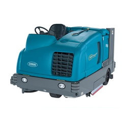
Tennant 285 Operator Manual
Tennant 285 sweeper/scrubber
TENNANT® 285 (Operator Manual). Sweeper/Scrubber.
Manual number MM191, revision 06, published 6-90.
About this manual
This manual is furnished with each new TENNANT® Model 285. It provides necessary operating and preventive maintenance instructions. Read this manual completely and understand the machine before operating or servicing it.
This manual covers all machine variations and standard accessories. The instruction portion of the manual consists of the Specification, Operation, Maintenance, and Appendix sections. The parts portion consists of the Low Dump Model Parts; Diesel Parts; Multi-Level Dump Model Parts; Accessories; Hydraulic Components; Engine Parts, Gasoline, LPG; and Engine Parts, Diesel; Cross Reference; and Customer Documents sections.
All right side and left side references to the machine are determined by facing the direction of forward travel. All hardware considered to be of a common nature or locally available has been omitted from the parts sections. Be aware that this machine may contain metric hardware. Make sure you use equivalent hardware when replacement becomes necessary.
This machine will provide excellent service. However, the best results will be obtained at minimum costs if:
- The machine is operated with reasonable care.
- The machine is maintained regularly – per the maintenance instructions provided.
- The machine is maintained with Tennant Company supplied or equivalent parts.
Parts and supplies may be ordered by phone or mail from any Tennant Company parts and service center, distributor, or from any of the Tennant Company subsidiaries. Before ordering parts or supplies, be sure to have your machine model number and serial number handy. Fill out the data block below for future reference. The telephone numbers, telex numbers, mailing addresses, and locations of those outlets are listed in the Customer Documents section of the manual.
Machine data
Please fill out at time of installation.
| Machine serial number | – |
|---|---|
| Engine serial number | – |
| Sales representative | – |
| Customer number | – |
| Date of installation | – |
| Manual number | MM191 |
| Revision | 06 |
| Published | 6-90 |
Trademark registered in: Austria, Benelux, Denmark, England, France, Germany, Italy, Spain, Switzerland, United States, Argentina, Australia, Canada, Japan, Mexico, Sweden, by TENNANT COMPANY, Minneapolis, Minnesota, U.S.A.
Acknowledgements: Technical information and/or illustrations supplied by Ford Motor Company; Cessna Fluid Power Division; Eaton Corporation, Hydraulics Division.
Copyright 1987, 1988, 1989, 1990 Tennant Company, Printed in U.S.A.
About this manual
The machine manual that you received with your TENNANT machine contains valuable information about the operation and maintenance, and numerous sections filled with TENNANT part numbers for the repair of the machine. Please read through this section titled ABOUT THIS MANUAL to become familiar with the contents of the machine manual, making the information you are looking for easier to find.
The machine manual consists of several sections of reference information, and the remainder contain part number information for ordering repair parts for the machine. Each section has a shaded bar at the top of the page with the name of that section. Just as this section has the title ABOUT THIS MANUAL on the top of each page. This way you can tell which section you are in at all times.
Reference sections
The reference information sections of the manual are; General Information, Specifications, Operation, Maintenance, and Appendix.
GENERAL INFORMATION – The General Information section of the manual contains the safety precautions, the location of the safety labels on the machine, and a table of contents of the entire manual. The Safety Precautions are an overview of the safety measures to be observed when operating and maintaining your machine. The location of the safety labels show the mounting location of the safety labels for use in the replacement of the labels. The table of contents in this section is a list of all the table of contents that appear in the front of each section in the manual. This can be used for easy reference to locate information in a particular section of the manual.
SPECIFICATIONS – The Specifications section of the manual contains machine specification information useful in the operation and maintenance of the machine. This section gives you specification information on the engine, electric motors, brake system, hydraulics, fluid capacities, and machine weight to mention a few. The section also has a illustration of the top and side view of the machine with the height and width dimensions displayed.
OPERATION – The Operation section of the manual contains information needed to operate the machine. This section will list the controls and instruments on the machine, overview the machine operation, and tell you how to transport and store the machine.
MAINTENANCE – The Maintenance section contains information on the suggested maintenance procedures and adjustments to keep your machine in top operating condition. The section includes a Maintenance Chart listing the maintenance schedule and the areas of the machine to be addressed. Each subject of maintenance is covered in more detail in such areas as Lubrication, Hydraulics, Engine, and Electrical System.
APPENDIX – The Appendix contains hardware and hydraulic information. Standard hardware torques and identification information is included, plus hydraulic torques if your machine is hydraulically controlled.
Part sections
The remaining sections of the manual contain part number information for ordering repair parts for your machine. The manual contains part number information on every type of machine model available in the model size of your particular machine. Therefore there will be part number information in your manual you will not need to refer to when wanting to place an order.
The main thing you need to know about your machine is what type of model is it. Is the machine powered by an engine or batteries? If the machine has an engine, is it fueled from gasoline, LPG, or gasoline? If it is a mid-sized or larger sweeper, is it multi-level or low dump? For the scrubbers, is it SRS® or standard. Determining this information about your machine will help guide you through the separate parts sections to find the repair part you need.
The smaller line of sweeper and scrubbers have less complicated part section arrangement, and are easier to find your way through the parts sections. The larger machines can have quite a variety of model types which significantly increases the size to the machine manual. Because of this, on the larger machine we made the first part section, Section 5, a part section which contains parts common to all type of the machine. If the machine has an engine, this section contains parts information on a gasoline powered machine.
The remaining sections contain only parts information which is unique to that particular machine type, such as unique diesel parts on the machine, or unique SRS® parts. Knowing the machine model type you have is important when searching for that part information you need for ordering repair parts. Start in that unique section first when looking for a part, then go to the first parts section, Section 5, if the part can’t be found in the unique section.
Machine serial numbers
When a design change takes place to a machine, the changes are indicated in the parts sections with machine serial numbers. Know the serial number of your machine which can be found on the machine data plate mounted on the machine. Record this number on the inside front cover of your manual along with your customer number.
Machine number usage is recorded in the Machine Serial Number column of the parts lists in the parts sections of the manual. If the machine serial number column lists zeros on the left side of the dash, then this part is used on all machines; such as (000000--- ).
If the column lists zeros on the left of the dash and a number on the right of the dash, then the part is used on machines up to and including that machine serial number; such as (00000---002345).
For parts that are used on machines beginning at and continuing on from a certain serial number, the column would list a serial number on the left of the dash and have blank spaces on the right side of the dash; such as (002346--- ). This part would be used on machines starting with that machine serial number and greater.
Finally, parts can be used on machines with serial numbers in a certain block of numbers. In this situation there is a serial number on the left and right side of the dash. The part is then used on a machine with a serial number starting at the number on the left and up to and including the number on the right; such as (002346---008900).
Parts assemblies
A part assembly has parts within the assembly, such as a parking brake consisting of other smaller parts. What parts are contained in a part assembly can be determined by an indentation arrangement in the description column of the parts lists. Here is an example of a part assembly, in this case we will use the parking brake mentioned previously:
| Machine serial number | Description | Qty. |
|---|---|---|
| (000000--- ) | Parking Brake | 1 |
| (000000--- ) | Pin, Roll | 1 |
| (000000--- ) | Link | 1 |
| (000000--- ) | Spring, Compression | 1 |
| (000000--- ) | Pin, Roll | 1 |
| (000000--- ) | Support | 1 |
| (000000--- ) | Lever, Release | 1 |
| (000000--- ) | Rod, Parking Brake | 1 |
| (000000--- ) | Washer, 0.50” | 3 |
In this example, the parts whose descriptions are indented under the parking brake are all parts of the parking brake. When you order the parking brake you will receive all the parts listed under it. You also can order any of the individual parts listed under the parking brake if it is the only part you need.
Supplier component breakdowns
TENNANT purchases certain components of the machine from suppliers. Some of these components are engines, hydraulic pumps and motors, electric motors, and solution pumps.
For those purchased components that are repairable, lists of parts for them appear in the later part of the parts sections. These are the supplier breakdowns. The engine breakdown contains both supplier and TENNANT parts numbers for repair parts. Breakdowns for hydraulic and electrical components have TENNANT part numbers for the parts TENNANT supplies. The serial numbers listed in any of the parts lists in these sections is a serial number the manufacturer uses to identify design changes in their particular component.
Ordering repair parts
Once you have located a part to order, there are several things you need to have to place the order. At the beginning of each parts section is an Ordering Repair Parts page which lists the information you will need to place your order. Review this list before placing the order.
This page is blank in the printed manual.
Safety precautions
The following symbols are used throughout this manual as indicated in their descriptions:
The following information signals potentially dangerous conditions to the operator or equipment. Read this manual carefully. Know when these conditions can exist. Locate all safety devices on the machine. Then, take necessary steps to train machine operating personnel. Report machine damage or faulty operation immediately. Do not use the machine if it is not in proper operating condition.
- Do not operate machine:
- Unless trained and authorized.
- Unless operation manual is read and understood.
- In flammable or explosive areas unless modified for use in those areas.
- In areas with possible falling objects unless equipped with overhead guard.
- Before starting machine:
- Check for fuel leaks (gasoline, LPG, diesel).
- Make sure all safety devices are in place and operate properly. See Operation section.
- Check brakes and steering for proper operation.
- When starting machine:
- Keep foot on brake and directional pedal in neutral.
- When using machine:
- Go slow on grades and slippery surfaces.
- Use care when backing machine.
- Do not carry riders on machine.
- Always follow safety and traffic rules.
- Before leaving or servicing machine:
- Stop on level surface.
- Set parking brake.
- Turn off machine and remove key.
- When servicing machine:
- Avoid moving parts. Do not wear loose jackets, shirts, or sleeves when working on machine.
- Use Tennant Company supplied or equivalent replacement parts.
Safety precautions (continued)
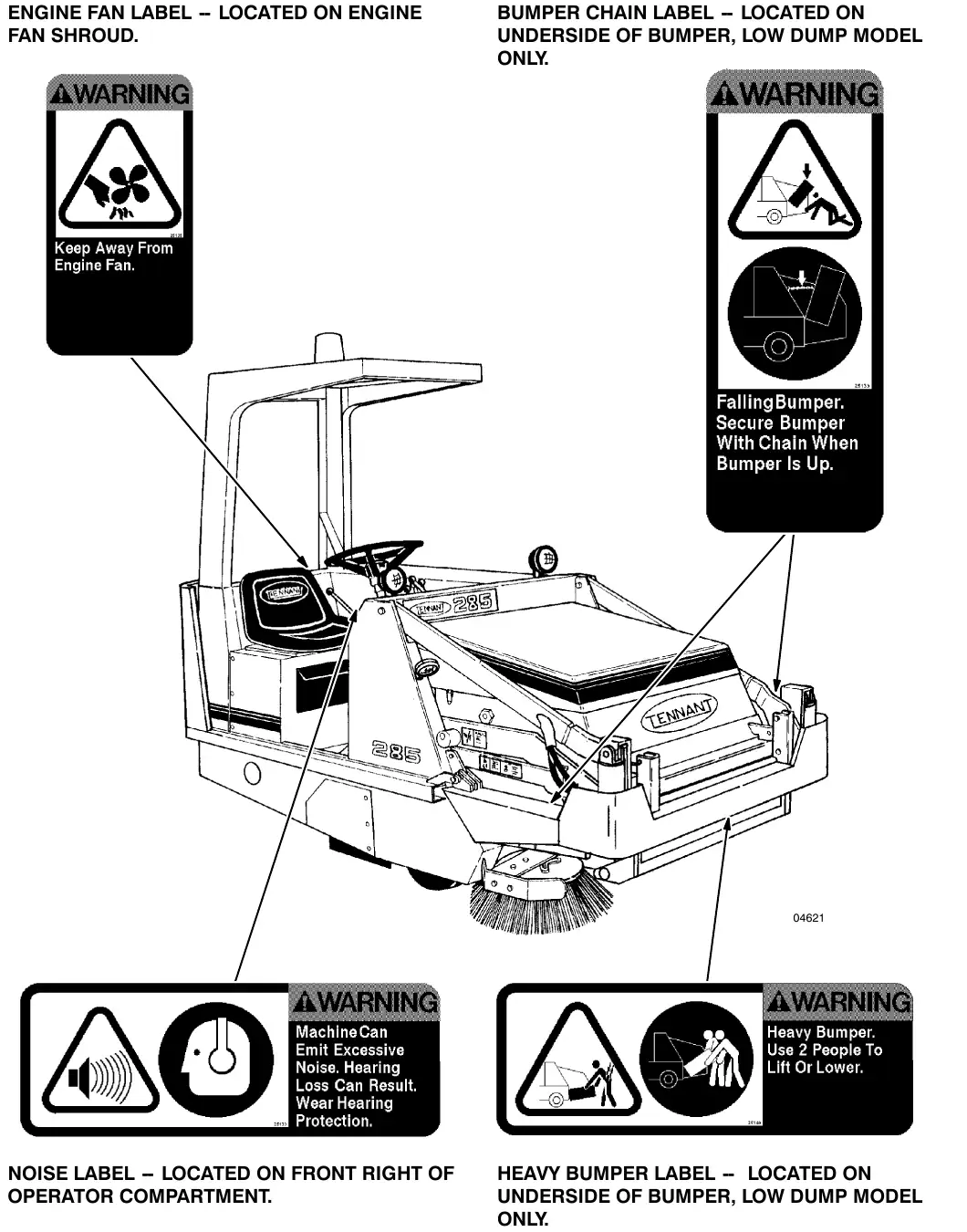
Safety label locations
The following safety labels are mounted on the machine in the locations indicated. If these, or any, labels become damaged or illegible, install a new label in its place.
- Engine fan label – located on engine fan shroud. Reads: “Warning. Keep Away From Engine Fan.”
- Bumper chain label – located on underside of bumper, low dump model only. Reads: “Warning. Falling Bumper. Secure Bumper With Chain When Bumper Is Up.”
- Noise label – located on front right of operator compartment. Reads: “Warning. Machine Can Emit Excessive Noise. Hearing Loss Can Result. Wear Hearing Protection.”
- Heavy bumper label – located on underside of bumper, low dump model only. Reads: “Warning. Heavy Bumper. Use 2 People To Lift Or Lower.”
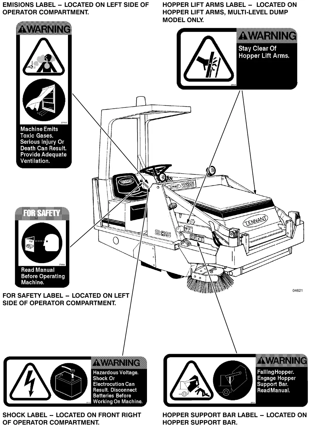
Safety label locations (continued)
- Emissions label – located on left side of operator compartment. Reads: “Warning. Machine Emits Toxic Gases. Serious Injury Or Death Can Result. Provide Adequate Ventilation.”
- Hopper lift arms label – located on hopper lift arms, multi-level dump model only. Reads: “Warning. Stay Clear Of Hopper Lift Arms.”
- For Safety label – located on left side of operator compartment. Reads: “For Safety. Read Manual Before Operating Machine.”
- Shock label – located on front right of operator compartment. Reads: “Warning. Hazardous Voltage. Shock Or Electrocution Can Result. Disconnect Batteries Before Working On Machine.”
- Hopper support bar label – located on hopper support bar. Reads: “Warning. Falling Hopper. Engage Hopper Support Bar. Read Manual.”
Contents
This contents list covers the whole printed manual package. The parts sections listed in it (sections 5 to 14) are not included in this operator manual file. See the parts page for this machine on our website.
General information (i)
Safety precautions (i)
Specifications (1-1)
- Machine specifications (1-3)
- Power type (1-3)
- Power train (1-3)
- Steering (1-3)
- Hydraulic system (1-3)
- Braking system (1-4)
- Suspension system (1-4)
- System fluid capacities (1-4)
- General machine dimensions/capacities (1-4)
- Machine weights (1-4)
- General machine performance (1-4)
- Machine dimensions (1-5)
Operation (2-1)
- Preparation for operation (2-3)
- After unloading and before operating the machine: (2-3)
- Operation of controls (2-4)
- Machine components – multi-level dump model shown (2-4)
- Instrument panel symbols (2-5)
- Controls and instruments (2-7)
- Brake pedal (2-8)
- Directional pedal (2-8)
- Parking brake lever (2-8)
- Operator seat (2-8)
- Squeegee switch (2-8)
- Water valve switch (2-8)
- Throttle lever (2-9)
- Throttle switch (2-9)
- Hazard light switch (2-9)
- Engine choke knob (2-9)
- Drive lights switch (2-9)
- Diesel preheat pushbutton and indicator (2-9)
- Hopper dump lever (2-9)
- Hopper lift and side brush lever (2-10)
- Main brush position lever (2-10)
- Steering wheel (2-10)
- Main brush height adjustment knob (2-10)
- Instrument panel (2-11)
- Thermal sentry™ indicator (2-11)
- Battery condition indicator (2-11)
- Hydraulic fluid temperature indicator (2-11)
- Engine coolant temperature indicator (2-11)
- Engine oil pressure indicator (2-12)
- Fuel level gauge (2-12)
- Clogged filter indicator (2-12)
- Filter shaker switch (2-12)
- Main brush and vacuum fan switch (2-12)
- Engine hour meter (2-12)
- Ignition and start switches (2-12)
- Side brush position lever (2-12)
- Hopper support bar (2-12)
- To engage hopper support bar (2-13)
- To disengage hopper support bar (2-13)
- Scrub brush position lever (2-14)
- Solution flow knob (2-14)
- Circuit breakers and relays (2-14)
- Machine operation (2-15)
- Normal sweeping operation (2-15)
- Pre-start checklist (2-15)
- To start machine (2-15)
- To sweep (2-16)
- To dump hopper (2-17)
- Post operation checklist – engine operating (2-17)
- To stop machine (2-17)
- Post operation checklist – engine stopped (2-17)
- Normal scrubbing operation (2-18)
- Pre-start checklist (2-18)
- To start machine (2-18)
- To scrub (2-19)
- To drain recovery tank and empty debris hopper (2-20)
- Post operation checklist – engine operating (2-20)
- To stop machine (2-21)
- Post operation checklist – engine stopped (2-21)
- Double scrubbing operation (2-21)
- Operation on grades (2-21)
- Vacuum wand (2-22)
- To operate vacuum wand (2-22)
- Hopper dolly (2-23)
- To remove hopper with dolly (2-23)
- To install hopper with dolly (2-24)
- Scrub attachment (2-24)
- To mount scrub attachment (2-24)
- To remove scrub attachment (2-27)
- Snow blade (2-29)
- To install snow blade (2-29)
- To operate snow blade (2-30)
- To remove snow blade (2-31)
Contents (continued)
- Snow broom (2-31)
- To install snow broom assembly (2-31)
- To operate snow broom (2-33)
- To remove snow broom assembly (2-34)
- Machine troubleshooting – sweeping (2-35)
- Machine troubleshooting – scrubbing (2-36)
- Transporting machine (2-37)
- Pushing or towing machine (2-37)
- Machine jacking (2-37)
- To jack up machine (2-37)
- Machine tie-downs (2-38)
- Machine storage (2-39)
- Storing machine (2-39)
Maintenance (3-1)
- Recommended first 50-hour machine inspection (3-3)
- Maintenance chart (3-4)
- Lubrication (3-6)
- Engine (3-6)
- Gasoline and LPG engines (3-6)
- Diesel engines (3-6)
- Steering gear (3-6)
- Rear wheel support (3-6)
- Front wheel bearings (3-6)
- Hopper lift arm pivots (3-7)
- Hopper door latches (3-7)
- Scrub attachment leg casters (3-8)
- Scrub attachment debris hopper (3-8)
- Hydraulics (3-9)
- Hydraulic fluid (3-9)
- Hydraulic fluid reservoir (3-9)
- To drain hydraulic fluid reservoir and replace filter element (3-10)
- To fill hydraulic fluid reservoir (3-11)
- Hydraulic pumps (3-11)
- Directional pedal (3-11)
- To adjust directional pedal (3-12)
- Lift arm speed limiter (3-13)
- Hydraulic fluid leaks (3-13)
- Hydraulic schematic, low dump model (3-14)
- Hydraulic schematic, multi-level dump model (3-15)
- Hydraulic system troubleshooting (3-16)
- Hydraulic components troubleshooting (3-18)
- Engine (3-19)
- Engine lubrication (3-19)
- Gasoline and LPG engines (3-19)
- Diesel engines (3-19)
- Cooling system (3-19)
- Air intake system (3-20)
- Air filter restriction indicator (3-21)
- Air filter (3-21)
- To replace air filter element (3-22)
- Fuel system – gasoline (3-23)
- Fuel filter (3-23)
- Fuel system – LPG (3-24)
- LPG fuel system (3-24)
- Fuel tanks (3-25)
- To change an LPG fuel tank (3-26)
- Fuel filter lock (3-26)
- Vaporizer-regulator (3-26)
- Carburetor (3-26)
- Oil pressure switch (3-26)
- LPG fuel troubleshooting (3-27)
- Fuel system – diesel (3-28)
- Diesel fuel system (3-28)
- Fuel water trap-filter (3-28)
- To replace fuel filter element (3-28)
- Priming fuel system (3-28)
- To prime fuel system (3-29)
- Governor – gasoline, LPG (For machines below serial number 010750) (3-29)
- To adjust governor (For machines below serial number 010750) (3-29)
- Governor – gasoline, LPG (For machines serial number 010750 and above) (3-30)
- Ignition system – gasoline, LPG (3-30)
- Spark plugs (3-30)
- Distributor (For machines below serial number 010750) (3-31)
- Engine ignition timing (For machines below serial number 010750) (3-31)
- To check and adjust ignition timing (For machines below serial number 010750) (3-31)
- Engine ignition timing (For machines serial number 010750 and above) (3-32)
- Cylinder head – gasoline, LPG (3-32)
- Cylinder head (3-32)
- Valve tappet clearance (3-32)
Contents (continued)
- Cylinder head – diesel (3-33)
- Cylinder head (3-33)
- Valve clearance (3-33)
- Crankcase ventilation system (3-33)
- Tune-up chart – gasoline, LPG (3-33)
- Electrical system (3-34)
- Battery (3-34)
- Electrical schematic – gasoline, LPG (For machines below serial number 010750) (3-35)
- Electrical schematic – gasoline, LPG (For machines serial number 010750 and above) (3-36)
- Electrical schematic – gasoline, LPG (For machines serial number 010750 and above) (3-37)
- Electrical schematic – diesel (3-38)
- Electrical schematic – diesel (For machines serial number 010750 and above) (3-39)
- Electrical schematic – diesel (For machines serial number 010750 and above) (3-40)
- Electrical schematic – auto shaker, RFS (3-41)
- Belts and chains (3-43)
- Engine fan belt (3-43)
- Governor belt – gasoline, LPG (For machines below serial number 010750) (3-43)
- Static drag chain (3-43)
- Debris hopper (3-44)
- Hopper dust filter (3-44)
- To remove hopper dust filter (3-44)
- To install hopper dust filter (3-44)
- Debris hopper (3-45)
- To adjust low dump model hopper (3-45)
- To adjust multi-level dump model hopper (3-46)
- Thermo Sentry™ (3-49)
- Brushes (3-50)
- Main brush (3-50)
- To replace main brush (3-50)
- To check and adjust main brush pattern (3-51)
- Side brush (3-52)
- To replace side brush (3-53)
- Skirts and seals (3-54)
- Hopper lip skirts (3-54)
- To replace hopper lip skirts (3-54)
- Brush door skirts (3-55)
- To replace and adjust brush door skirts (3-55)
- Rear skirts (3-56)
- To replace and adjust the rear skirts (3-56)
- Main brush door seals (3-57)
- Hopper seals (3-57)
- Hopper inspection door seal (3-57)
- Hopper door seals (3-58)
- Hopper cover seal (3-58)
- Hopper vacuum fan seal (3-58)
- Brakes and tires (3-59)
- Service brakes (3-59)
- To adjust brake linkage (3-59)
- Parking brakes (3-59)
- Tires (3-59)
- Scrub attachment (3-60)
- Scrub attachment (3-60)
- Solution tanks (3-60)
- Solution distribution system (3-60)
- Scrub brushes (3-60)
- To replace scrub brush (3-61)
- To check and adjust scrub brush pattern (3-61)
- Recovery tank (3-63)
- To drain the recovery tank (3-63)
- To clean the recovery tank (3-63)
- Debris hopper (3-64)
- Side squeegee (3-65)
- To replace side squeegee blade (3-65)
- Rear squeegee (3-66)
- To replace or rotate rear blade (3-66)
- To replace or rotate front blade (3-67)
- To check and adjust rear squeegee (3-68)
- Snow broom (3-70)
- Snow broom (3-70)
- To replace snow broom (3-70)
Appendix (4-1)
- Hardware information (4-3)
- Standard bolt torque chart (4-3)
- Metric bolt torque chart (4-3)
- Bolt identification (4-3)
- Thread sealant and locking compounds (4-3)
- Hydraulic fitting information (4-4)
- Hydraulic tapered pipe fitting (npt)torque chart (4-4)
- Hydraulic tapered seat fitting (JIC) torque chart (4-4)
- Hydraulic o–ring fitting torque chart (4-4)
Contents (continued)
Low dump model parts (5-1)
- Ordering repair parts (5-3)
- Fig. 1 – Recommended General Maintenance Items (5-4)
- Fig. 2 – Replacement Brushes (5-6)
- Fig. 3 – Main Frame Group (5-8)
- Fig. 4 – Seat and Radiator Group (5-10)
- Fig. 5 – Engine Cover and Side Door Group (5-12)
- Fig. 6 – Hopper Group (5-14)
- Fig. 7 – Hopper Cover and Filter Group (5-16)
- Fig. 8 – Hopper Lift Arms Group (5-18)
- Fig. 9 – Side Brush Group (5-20)
- Fig. 10 – Front Wheel and Brakes Group (5-22)
- Fig. 11 – Steering Control Group (5-24)
- Fig. 12 – Rear Wheel Drive Group (5-26)
- Fig. 13 – Main Brush Drive Group (5-28)
- Fig. 14 – Main Brush Lift Group (5-29)
- Fig. 15 – Access and Kick Panels Group (5-30)
- Fig. 16 – Vacuum Fan Group (5-31)
- Fig. 17 – Instrument and Control Panels Group (5-32)
- Fig. 18 – Battery Group (5-33)
- Fig. 19 – Wire Harnesses Group (5-34)
- Fig. 20 – Hydraulic Hoses Group (5-36)
- Fig. 21 – Hydraulic Pumps Group (5-38)
- Fig. 22 – Hydraulic Reservoir Group (5-39)
- Fig. 23 – Hydraulic Control Valve Group (5-40)
- Fig. 24 – Hydraulic Solenoid Valve Group (5-41)
- Fig. 25 – Hydraulic Filter Group (5-42)
- Fig. 26 – Hydraulic Couplings Group (5-43)
- Fig. 27 – Engine Group (5-44)
- Fig. 28 – Fuel Tank Bumper Group, LPG (5-46)
- Fig. 29 – Carburetor Group, LPG (5-48)
- Fig. 30 – Sheaves and Belts Group (5-49)
- Fig. 31 – Air Cleaner Group (5-50)
- Fig. 32 – Directional Control Group (5-51)
- Fig. 33 – Flywheel Housing Group (5-52)
- Fig. 34 – Throttle Linkage Group (5-54)
- Fig. 35 – Muffler Group (5-55)
- Fig. 36 – Fuel Tank Group (5-56)
- Fig. 37 – Labels Group (5-57)
- Fig. 38 – Headlight, Taillight, and Spotlight Group (5-58)
- Fig. 39 – Pressure Switch Group (5-59)
- Fig. 40 – Overhead Guard Group (5-60)
Diesel parts (6-1)
- Ordering repair parts (6-3)
- Fig. 1 – Engine Group, Diesel (6-4)
- Fig. 2 – Fuel Tank Group, Diesel (6-6)
- Fig. 3 – Radiator and Shroud Group, Diesel (6-8)
- Fig. 4 – Throttle Linkage Group, Diesel (6-9)
- Fig. 5 – Muffler Group, Diesel (6-10)
- Fig. 6 – Directional Control Group, Diesel (6-11)
- Fig. 7 – Instruction Panel Group, Diesel (6-12)
- Fig. 8 – Wire Harness Group, Diesel (6-13)
- Fig. 9 – Foam Insulation Group, Diesel (6-14)
- Fig. 10 – Air Cleaner Group, Diesel (6-15)
Multi –level dump model parts (7-1)
- Ordering repair parts (7-3)
- Fig. 1 – Main Frame Group, Multi-level Dump (7-4)
- Fig. 2 – Hopper Door Assembly, Multi-level Dump (7-5)
- Fig. 3 – Hopper Group, Multi-level Dump (7-6)
- Fig. 4 – Hopper Lift Arms Group, Multi-level Dump (7-8)
- Fig. 5 – Hopper Cover and Filter Carrier Group, Multi-level Dump (7-10)
- Fig. 6 – Hydraulic Lift Cylinder Group, Multi-level Dump (7-11)
- Fig. 7 – Stabilizer Leg Group, Multi-level Dump (7-12)
- Fig. 8 – Side Brush Group, Multi-level Dump (7-13)
- Fig. 9 – Main Brush Lift Group, Multi-level Dump (7-14)
- Fig. 10 – Hydraulic Hoses Group, Multi-level Dump (7-15)
- Fig. 11 – Hydraulic Control Valve Group, Multi-level Dump (7-16)
- Fig. 12 – Wire Harnesses Group, Multi-level Dump (7-17)
- Fig. 13 – Pressure Switch Group, Multi-level Dump (7-18)
Accessories (8-1)
- Ordering repair parts (8-3)
- Fig. 1 – Cab Kit (8-4)
- Fig. 2 – Snow Blade Kit (8-6)
- Fig. 3 – Snow Broom Kit (8-8)
- Fig. 4 – Mount Frame Kit (8-10)
- Fig. 5 – Tire Chain Kit (8-11)
- Fig. 6 – Tire and Wheel Assembly (8-11)
- Fig. 7 – Revolving Light Kit, Overhead Guard (8-12)
- Fig. 8 – Flashing Light Kit, Overhead Guard (8-13)
- Fig. 9 – Revolving Light Kit, Shroud (8-14)
- Fig. 10 – Flashing Light Kit, Shroud (8-15)
- Fig. 11 – Revolving Light Kit, Cab (8-16)
- Fig. 12 – Flashing Light Kit, Cab (8-17)
- Fig. 13 – Rear Squeegee Group (8-18)
- Fig. 14 – Side Squeegee Group (8-20)
- Fig. 15 – Scrub Attachment Cam Group (8-21)
- Fig. 16 – Scrub Brush Drive Group (8-22)
- Fig. 17 – Solution Tanks Group (8-24)
- Fig. 18 – Recovery Tank Group (8-26)
Contents (continued)
- Fig. 19 – Main Scrubber Brush Group (8-28)
- Fig. 20 – Instrument Panel Group (8-28)
- Fig. 21 – Hopper Dolly Assembly (8-29)
- Fig. 22 – Scrubber Bumper Group (8-30)
- Fig. 23 – Dry Battery Kit (8-31)
- Fig. 24 – Vacuum Wand Kit, Low Dump (8-32)
- Fig. 25 – Vacuum Wand Group, Multi–level Dump (8-34)
- Fig. 26 – Battery Hold Down Kit (8-36)
- Fig. 27 – Fire Extinguisher Kit (8-37)
- Fig. 28 – Alternator Kit (8-37)
- Fig. 29 – Spark Arresting Muffler Kit (8-38)
- Fig. 30 – Protectoseal Fuel Tank Cap Kit (8-38)
- Fig. 31 – Hood Latch and Machine Tie–Down Kit (8-39)
- Fig. 32 – Fuel Tanks Group, LPG (8-40)
- Fig. 33 – Rear Wheel Assembly, Foam Filled (8-41)
- Fig. 34 – Rear Wheel Assembly, Solid (8-41)
- Fig. 35 – Extra Reach Side Brush Group, Multi-level Dump (8-42)
- Fig. 36 – Maximum Path Side Brush Group (8-43)
- Fig. 37 – Hopper and Cover Group, RFS (8-44)
- Fig. 38 – Filter and Shaker Group, RFS (8-46)
- Fig. 39 – Vacuum System Group, RFS (8-48)
- Fig. 40 – Electrical and Hydraulic Group, RFS (8-50)
- Fig. 41 – Switch and Circuit Group, RFS (8-52)
- Fig. 42 – Wire Harnesses Group, RFS (8-53)
Hydraulic components (9-1)
- Ordering repair parts (9-3)
- Fig. 1 – Hydraulic Piston Pump Breakdown 02704 (9-4)
- Fig. 2 – Pump Hydraulic Gear Breakdown 82205 (9-6)
- Fig. 3 – Hydraulic Motor Breakdown 48663 (9-7)
- Fig. 4 – Hydraulic Motor Breakdown 13106 (9-8)
- Fig. 5 – Hydraulic Motor Breakdown 27800 (9-9)
- Fig. 6 – Hydraulic Motor Breakdown 13105 (9-10)
- Fig. 7 – Hydraulic Motor Breakdown 28808 (9-11)
- Fig. 8 – Hydraulic Motor Breakdown 77101 (9-12)
- Fig. 9 – Hydraulic Motor Breakdown 27796 (9-13)
- Fig. 10 – Hydraulic Motor Breakdown 27787 (9-14)
- Fig. 11 – Hydraulic Valve Breakdown 62550 (9-15)
- Fig. 12 – Hydraulic Valve Breakdown 34319 (9-16)
- Fig. 13 – Hydraulic Solenoid Valve Breakdown 82754 (9-17)
- Fig. 14 – Hydraulic Cylinder Breakdown 04468 (9-18)
- Fig. 15 – Hydraulic Cylinder Breakdown 82757 (9-19)
- Fig. 16 – Hydraulic Cylinder Breakdown 04471 (9-20)
Engine parts, gasoline, LPG (10-1)
- Ordering repair parts (10-3)
- Fig. 1 – Cylinder Head Group (10-4)
- Fig. 2 – Cylinder Block Group (10-6)
- Fig. 3 – Camshaft Group (10-8)
- Fig. 4 – Crankshaft and Piston Group (10-10)
- Fig. 5 – Oil Pump and Oil Pan Group (10-12)
- Fig. 6 – Intake and Exhaust Manifold Group (10-14)
- Fig. 7 – Front Cover Group (10-15)
- Fig. 8 – Water Pump Group (10-16)
- Fig. 9 – Distributor Group (10-18)
- Fig. 10 – Gaskets Group (10-20)
- Fig. 11 – Flywheel Group (10-22)
Engine parts, DIS, gasoline, LPG (11-1)
- Ordering repair parts (11-3)
- Fig. 1 – Cylinder Head, Valves Group (11-4)
- Fig. 2 – Cylinder Block Group (11-6)
- Fig. 3 – Camshaft and Valve Control Group (11-8)
- Fig. 4 – Crankshaft and Piston Group (11-10)
- Fig. 5 – Oil Pump and Oil Pan Group (11-12)
- Fig. 6 – Intake Manifold Group (11-14)
- Fig. 7 – Front Cover Assembly Group (11-15)
- Fig. 8 – Water Pump Group (11-16)
- Fig. 9 – Distributorless Ignition Group (11-17)
- Fig. 10 – Gaskets Group (11-18)
- Fig. 11 – Flywheel Group (11-19)
Engine parts, diesel (12-1)
- Ordering repair parts (12-3)
- Fig. 1 – Crankcase Group (12-4)
- Fig. 2 – Oil Pan Group (12-6)
- Fig. 3 – Cylinder Head Group (12-7)
- Fig. 4 – Gear Case Group (12-8)
- Fig. 5 – Main Bearing Case Group (12-10)
- Fig. 6 – Inlet Manifold Group (12-11)
- Fig. 7 – Valve, Rocker Arm Group (12-12)
- Fig. 8 – Head Cover Group (12-14)
- Fig. 9 – Piston and Crankshaft Group (12-16)
- Fig. 10 – Camshaft Group (12-18)
- Fig. 11 – Flywheel Group (12-19)
- Fig. 12 – Nozzle Group (12-20)
- Fig. 13 – Fuel Camshaft Group (12-22)
Contents (continued)
- Fig. 14 – Governor Group (12-24)
- Fig. 15 – Speed Control Plate Group (12-25)
- Fig. 16 – Stop Lever Group (12-26)
- Fig. 17 – Thermostat Group (12-27)
- Fig. 18 – Water Pump Group (12-28)
- Fig. 19 – Starter Breakdown (12-29)
Cross reference (13-1)
- Part number to page number cross reference list (13-3)
Customer documents (14-1)
- Tennant company limited warranty (14-3)
- Tennant company, tennant company subsidiaries, and major parts and service locations directory (14-5)
Specifications contents
- Machine specifications (1-3)
- Power type (1-3)
- Power train (1-3)
- Steering (1-3)
- Hydraulic system (1-3)
- Braking system (1-4)
- Suspension system (1-4)
- System fluid capacities (1-4)
- General machine dimensions/capacities (1-4)
- Machine weights (1-4)
- General machine performance (1-4)
- Machine dimensions (1-5)
This page is blank in the printed manual.
Machine specifications
Power type
Gasoline and LPG engine
| Item | Specification |
|---|---|
| Engine type | piston |
| Ignition | breakerless-type spark |
| Cycle | 4 |
| Aspiration | natural |
| Cylinders | 4 |
| Bore | 2.91 in (74 mm) |
| Stroke | 2.97 in (75 mm) |
| Displacement | 79 cu in (1300 cc) |
| Net power | 28.5 hp (21.2 kW) @ 2200 rpm, governed |
| Net power | 35.5 hp (26.5 kW) @ 2650 rpm, governed |
| Net power | 53.7 hp (40 kW) @ 4000 rpm, maximum |
| Fuel | gasoline, 87 octane minimum, unleaded or LPG |
| Cooling system | water/ethylene glycol antifreeze |
| Electrical system | 12 V nominal, 37 A alternator |
Diesel engine
| Item | Specification |
|---|---|
| Engine type | piston |
| Ignition | diesel |
| Cycle | 4 |
| Aspiration | natural |
| Cylinders | 3 |
| Bore | 3.25 in (85 mm) |
| Stroke | 3.23 in (82 mm) |
| Displacement | 85 cu in (1395 cc) |
| Net power | 27 hp (20 kW) @ 2200 rpm, governed |
| Net power | 31 hp (23 kW) @ 2650 rpm, governed |
| Net power | 32 hp (24 kW) @ 3600 rpm, maximum |
| Fuel | diesel, No.1 or No.2 |
| Cooling system | water/ethylene glycol antifreeze |
| Electrical system | 12 V nominal, 37 A alternator |
Power train
| Item | Specification |
|---|---|
| Propelling | hydraulic drive motor, rear wheel |
| Main brush | hydraulic drive motor |
| Side brush | hydraulic drive motor |
| Vacuum fan | hydraulic drive motor |
Steering
| Item | Specification |
|---|---|
| Type | rear wheel controlled, automotive worm and sector gear |
| Power source | manual |
Hydraulic system
| Item | Specification |
|---|---|
| Function | operates propelling, hopper lift, hopper dump, main brush drive, side brush drive, and vacuum fan drive. |
| Control valve, low dump model, side brush drive, hopper lift | open center type, single spool. |
| Control valve, multi-level dump model, side brush drive, hopper lift, hopper dump | open center type, two spool. |
| Control valve, vacuum fan drive, main brush drive | open center type, single spool, solenoid operated. |
| Pump, propelling | variable displacement piston type, 1.24 cu in (20 cc) maximum displacement per revolution, 11.8 gpm (45 L/min) @ 2200 rpm, 14.2 gpm (54 L/min) @ 2650 rpm |
| Propelling system relief pressure | 4000 psi (27,580 kPa) |
| Pump, accessories | gear type, 1.02 cu in (14 cc) displacement, 9.5 gpm (36 L/min) @ 2200 rpm, 12.3 gpm (47 L/min) @ 2650 rpm. |
| Side brush and lift cylinder system relief pressure | 1900 psi (13,100 kPa) |
| Vacuum fan and main brush motor system relief pressure | 2150 psi (14,825 kPa) |
| Motor, propelling | internal gear type, 19 cu in (310 cc) displacement per revolution, 4500 psi (31,030 kPa) maximum rated pressure. |
| Motor, main brush | internal gear type, 4.5 cu in (75 cc) displacement per revolution, 2500 psi (17,240 kPa) maximum rated pressure |
| Motor, side brush | internal gear type, 2.8 cu in (45 cc) displacement per revolution, 1500 psi (10,340 kPa) maximum rated pressure |
| Motor, vacuum fan | external gear type, 0.26 cu in (5 cc) displacement per revolution, 3000 psi (20,685 kPa) maximum rated pressure |
| Cylinder, hopper lift, low dump model | single action type, 2.5 in (65 mm) bore x 6 in (150 mm) stroke, 1.12 in (29 mm) diameter rod, 2500 psi (17,240 kPa) maximum rated pressure |
| Cylinder, hopper lift, multi-level dump model | single action type, 3.5 in (90 mm) bore x 8 in (205 mm) stroke, 1.25 in (32 mm) diameter rod, 2500 psi (17,240 kPa) maximum rated pressure |
Machine specifications (continued)
Hydraulic system (continued)
| Item | Specification |
|---|---|
| Cylinder, hopper dump, multi-level dump model | double action type, 2 in (50 mm) bore x 5.38 in (135 mm) stroke, 1 in (25 mm) diameter rod, 2500 psi (17,240 kPa) maximum rated pressure |
Braking system
| Item | Specification |
|---|---|
| Service brakes | mechanical drum brakes (2), one per front wheel, linkage actuated |
| Parking brakes | utilize service brakes, linkage actuated |
Suspension system
| Item | Specification |
|---|---|
| Front | two 4 x 16 solid tires |
| Rear | one 5.70 x 8 pneumatic tire |
| Rear | one 5.00 x 8 solid tire accessory |
System fluid capacities
| Item | Specification |
|---|---|
| Engine cooling system, gasoline, LPG radiator | 4 qt (3.8 L) |
| Engine cooling system, gasoline, LPG total | 16 qt (15 L) |
| Engine cooling system, diesel radiator | N/A qt (N/A L) |
| Engine cooling system, diesel total | N/A qt (N/A L) |
| Engine lubricating oil, gasoline, LPG | 3.5 qt (3.3 L) with filter |
| Engine lubricating oil, diesel | 7 qt (6.7 L) with filter |
| Fuel tank, gasoline, diesel | 7.8 gal (30 L) |
| Fuel tank, LPG | 33 lb (15 kg) |
| Hydraulic system, reservoir | 5 gal (19 L) |
| Hydraulic system, total | 6.3 gal (24 L) |
General machine dimensions/capacities
| Item | Specification |
|---|---|
| Length, low dump model | 96 in (2440 mm) |
| Length, multi-level dump model | 98 in (2490 mm) |
| Width, low dump model | 56 in (1420 mm) |
| Width, multi-level dump model | 59 in (1500 mm) |
| Height | 52 in (1320 mm) |
| Height with overhead guard | 79 in (2005 mm) |
| Height with overhead guard and hazard lamp | 85 in (2160 mm) |
| Height with cab | 77 in (1955 mm) |
| Height with cab and hazard lamp | 83 in (2110 mm) |
| Track | 46 in (1170 mm) |
| Wheelbase | 38 in (965 mm) |
| Main brush diameter | 14 in (355 mm) |
| Main brush length | 42 in (1065 mm) |
| Side brush diameter | 21 in (535 mm) |
| Sweeping path width | 42 in (1065 mm) |
| Sweeping path width with side brush | 53 in (1345 mm) |
| Hopper capacity | 1000 lb (455 kg) |
| Hopper capacity | 14 cu ft (0.4 m³) |
| Dust filter area | 110 sq ft (10.2 m²) |
Machine weights
| Item | Specification |
|---|---|
| Net weight, low dump model | 2150 lb (975 kg) |
| Net weight, multi-level dump model | 2800 lb (1270 kg) |
| GVWR, low dump model | 3200 lb (1450 kg) |
| GVWR, multi-level dump model | 3800 lb (1725 kg) |
General machine performance
| Item | Specification |
|---|---|
| Maximum forward speed | 8.5 mph (13.7 km/h) |
| Maximum reverse speed | 4.2 mph (6.8 km/h) |
| Minimum isle turn width, right, low dump model | 157 in (3990 mm) |
| Minimum isle turn width, left, low dump model | 111 in (2820 mm) |
| Minimum isle turn width, right, multi-level dump model | 161 in (4090 mm) |
| Minimum isle turn width, left, multi-level dump model | 111 in (2820 mm) |
| Maximum rated climb/descent angle | 10° with full hopper, 15° with an empty hopper |
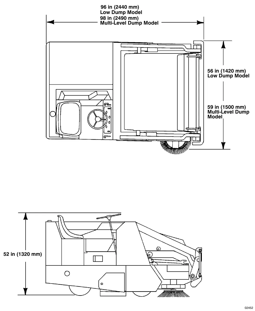
Machine dimensions
| Dimension | Low dump model | Multi-level dump model |
|---|---|---|
| Length | 96 in (2440 mm) | 98 in (2490 mm) |
| Width | 56 in (1420 mm) | 59 in (1500 mm) |
| Height | 52 in (1320 mm) | |
This page is blank in the printed manual.
Operation contents
- Preparation for operation (2-3)
- After unloading and before operating the machine: (2-3)
- Operation of controls (2-4)
- Machine components – multi-level dump model shown (2-4)
- Instrument panel symbols (2-5)
- Controls and instruments (2-7)
- Brake pedal (2-8)
- Directional pedal (2-8)
- Parking brake lever (2-8)
- Operator seat (2-8)
- Squeegee switch (2-8)
- Water valve switch (2-8)
- Throttle lever (2-9)
- Throttle switch (2-9)
- Hazard light switch (2-9)
- Engine choke knob (2-9)
- Drive lights switch (2-9)
- Diesel preheat pushbutton and indicator (2-9)
- Hopper dump lever (2-9)
- Hopper lift and side brush lever (2-10)
- Main brush position lever (2-10)
- Steering wheel (2-10)
- Main brush height adjustment knob (2-10)
- Instrument panel (2-11)
- Thermal sentry™ indicator (2-11)
- Battery condition indicator (2-11)
- Hydraulic fluid temperature indicator (2-11)
- Engine coolant temperature indicator (2-11)
- Engine oil pressure indicator (2-12)
- Fuel level gauge (2-12)
- Clogged filter indicator (2-12)
- Filter shaker switch (2-12)
- Main brush and vacuum fan switch (2-12)
- Engine hour meter (2-12)
- Ignition and start switches (2-12)
- Side brush position lever (2-12)
- Hopper support bar (2-12)
- To engage hopper support bar (2-13)
- To disengage hopper support bar (2-13)
- Scrub brush position lever (2-14)
- Solution flow knob (2-14)
- Circuit breakers and relays (2-14)
- Machine operation (2-15)
- Normal sweeping operation (2-15)
- Pre-start checklist (2-15)
- To start machine (2-15)
- To sweep (2-16)
- To dump hopper (2-17)
- Post operation checklist – engine operating (2-17)
- To stop machine (2-17)
- Post operation checklist – engine stopped (2-17)
- Normal scrubbing operation (2-18)
- Pre-start checklist (2-18)
- To start machine (2-18)
- To scrub (2-19)
- To drain recovery tank and empty debris hopper (2-20)
- Post operation checklist – engine operating (2-20)
- To stop machine (2-21)
- Post operation checklist – engine stopped (2-21)
- Double scrubbing operation (2-21)
- Operation on grades (2-21)
- Vacuum wand (2-22)
- To operate vacuum wand (2-22)
- Hopper dolly (2-23)
- To remove hopper with dolly (2-23)
- To install hopper with dolly (2-24)
- Scrub attachment (2-24)
- To mount scrub attachment (2-24)
- To remove scrub attachment (2-27)
- Snow blade (2-29)
- To install snow blade (2-29)
- To operate snow blade (2-30)
- To remove snow blade (2-31)
- Snow broom (2-31)
- To install snow broom assembly (2-31)
- To operate snow broom (2-33)
- To remove snow broom assembly (2-34)
- Machine troubleshooting – sweeping (2-35)
- Machine troubleshooting – scrubbing (2-36)
- Transporting machine (2-37)
- Pushing or towing machine (2-37)
- Machine jacking (2-37)
- To jack up machine (2-37)
- Machine tie-downs (2-38)
- Machine storage (2-39)
- Storing machine (2-39)
This page is blank in the printed manual.
Preparation for operation
After unloading and before operating the machine
- Check the machine for shipping damage.
- Read this manual carefully before operating or servicing the machine.
FOR SAFETY: Do not operate the machine unless operation manual is read and understood.
- Check the hydraulic fluid level in the hydraulic fluid reservoir, using the dipstick provided. TENNANT® hydraulic fluid is recommended. If TENNANT® hydraulic fluid is not available, use only new, approved hydraulic fluid. See Hydraulics in the Maintenance section.
- Check the engine oil level.
- Check the radiator coolant level.
WARNING: Hot engine coolant. Scalding can result. Do not open radiator cap or service cooling system until radiator and engine is cool to the touch.
- Check the main brush adjustment, as described in Brushes in the Maintenance section.
- Check the air pressure of the rear tire.
- Fill the fuel tank, or install an LPG fuel tank on the machine.
WARNING: Machine can have static electricity charge. When pouring fuel, spark can ignite fuel causing fire or explosion. Connect wire attached to fuel can to machine to discharge spark before pouring fuel.
Operation of controls
Machine components – multi-level dump model shown
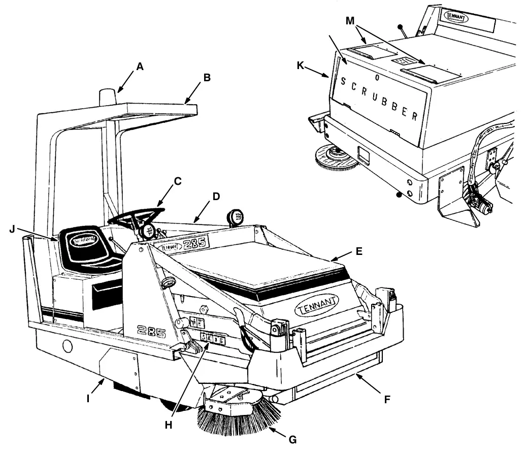
| Letter | Component | Letter | Component |
|---|---|---|---|
| A | Hazard Light | H | Hopper Support Bar |
| B | Overhead Guard | I | Main Brush Access Door |
| C | Steering Wheel | J | Operator Seat |
| D | Engine Cover | K | Scrub Attachment |
| E | Hopper Cover | L | Front Access Door |
| F | Hopper Door | M | Solution Tank Covers |
| G | Side Brush |
Instrument panel symbols
The symbols are used to identify controls and displays on the machine:
| Symbol | Meaning |
|---|---|
 | Squeegee Up |
 | Squeegee Down |
 | Solution Flow |
 | Diesel Off |
 | Idle |
 | Fast 1 |
 | Fast 2 |
 | Hopper Roll Out |
 | Hopper Roll In/Out Hold |
 | Hopper Roll In |
 | Side Brush On |
 | Hopper Up |
 | Hopper Down |
 | Hopper Hold |
 | Headlights |
 | Hazard Light |
 | Main Brush Free-Float |
 | Main Brush Down |
 | Main Brush Up |
 | Engine Oil Pressure |
 | Engine Water Temperature |
 | Hydraulic Fluid Temperature |
 | Battery/Alternator/Charging System |
 | Hopper Temperature – Thermo Sentry™ |
 | Engine Shutdown |
 | Fuel Level |
Instrument panel symbols (continued)
| Symbol | Meaning |
|---|---|
 | Filter Shaker |
 | Filter Clogged |
 | Main Brush On |
 | Hourmeter |
 | Engine Start |
 | Key Switch |
 | Side Brush Down |
 | Side Brush Up |
 | Circuit Breaker 1 |
 | Circuit Breaker 2 |
 | Circuit Breaker 3 |
 | Circuit Breaker 4 |
 | Circuit Breaker 5 |
 | Circuit Breaker 6 |
 | Circuit Breaker 7 |
Controls and instruments
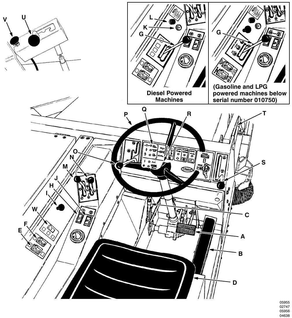
| Letter | Control | Letter | Control |
|---|---|---|---|
| A | Brake Pedal | M | Hopper Dump Lever |
| B | Directional Pedal | N | Hopper Lift and Side Brush Lever |
| C | Parking Brake Lever | O | Main Brush Position Lever |
| D | Operator Seat | P | Steering Wheel |
| E | Squeegee Switch | Q | Instrument Panel |
| F | Water Valve Switch | R | Horn Button |
| G | Throttle Lever | S | Side Brush Position Lever |
| H | Hazard Light Switch | T | Hopper Support Bar |
| I | Engine Choke Knob | U | Scrub Brush Position Lever |
| J | Drive Lights Switch | V | Solution Flow Knob |
| K | Diesel Preheat Indicator | W | Throttle Switch |
| L | Diesel Preheat Pushbutton |
Brake pedal
The brake pedal operates the mechanical drum brakes on the two front wheels.
To stop the machine, return the directional pedal to neutral; then apply pressure to the brake pedal.
Directional pedal
The directional pedal controls the propelling drive. It is used to select the direction of travel and the propelling speed of the machine.
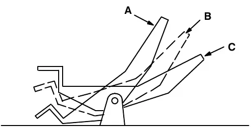
To travel forward, press the “toe” portion of the pedal; to travel backward, press the “heel” portion of the pedal. The propelling speed of the machine is regulated by varying the pressure on the pedal.
Parking brake lever
The parking brake lever operates the front wheel brakes. To engage the parking brake, push the parking brake handle down. To disengage the parking brake, pull the brake handle up. Always park on a level surface, stop the engine, and engage the parking brake before leaving the machine unattended and before working on the machine.
Operator seat
The operator seat is three-way adjustable. It has adjustments to vary bounce, to vary the backrest angle, and to vary the front-to-rear seat position. of a fixed back style with a forward–backward adjustment. The operator seat also tilts forward to allow access to the fuel tank.
The weight lever has three positions. One for light operators, one for medium weight operators, and one for heavy operators. Pull the lever up for light operators; position the lever horizontally for medium operators; and down for heavy operators.
The backrest angle is adjusted by turning the knob. Turn the knob clockwise to decrease the angle and counter-clockwise to increase the angle.
The seat position is adjusted by pulling the lever in front of the seat out to the left, sliding the seat to a comfortable position and releasing the lever.
Squeegee switch
The squeegee switch is present on machines equipped with the rear squeegee or scrub attachment accessories. The switch controls the position of the rear squeegee.
To raise the rear squeegee, place the switch in the top (Squeegee Up) position. To lower the rear squeegee, place the switch in the bottom (Squeegee Down) position.
Water valve switch
The water valve switch is present on machines equipped with the scrub attachment accessory. The switch controls solution flow to the floor. The solution flow knob mounted on the scrub attachment controls the solution flow rate to the floor.
To start the solution flow to the floor from the scrub attachment tank, place the switch into the top position. To stop the solution flow to the floor, place the switch into the bottom position.
Throttle lever
The throttle lever controls the engine governed speed on gasoline and LPG powered machines below serial number 010750. The throttle lever controls the engine governed speed and stops the engine on all diesel powered machines.
When starting the engine and to slow the engine speed to idle, push the lever into the (Idle) position.
To pick up normal debris, speed the engine to the normal governed speed by pulling the lever into the middle (Fast 1) position.
To pick up light litter, speed the engine to the maximum governed speed by pulling the lever to the left into the (Fast 2) position.
To stop the engine on a diesel powered machine, pull the lever all the way to the right into the (Diesel Off) position.
Throttle switch
The throttle switch controls engine governed speed on gasoline and LPG powered machines serial number 010750 and above.
When starting the engine and to slow the engine speed to idle, place the switch in the top (Engine Start) position.
To pick up normal debris, speed the engine to the normal governed speed by placing the switch in the bottom (Fast 1) position.
To pick up light litter, speed the engine to the maximum governed speed by placing the switch in the middle (Fast 2) position.
Hazard light switch
The hazard light switch is present on machines with rotating or flashing light accessory. To operate the light, place the switch in the top position. To turn off the light, place the switch in the bottom position.
Engine choke knob
The engine choke knob controls the engine choke on gasoline powered machines.
To close the choke for cold starting, pull the choke knob out.
To open the choke, push the knob in.
Drive lights switch
The drive lights switch is present on machines with the operating lights accessory. The switch controls the headlights, taillights, and side brush spot light. To operate the lights, place the switch in the top position. To turn off the lights, place the switch in the bottom position.
Diesel preheat pushbutton and indicator
The diesel preheat pushbutton and indicator are present on diesel powered machines. The pushbutton controls the engine preheaters. The indicator glows brightly when the preheaters are up to starting temperature.
To use engine preheaters, push and hold the preheat pushbutton until the indicator glows brightly – usually fifteen to thirty seconds. Then release pushbutton and start engine.
Hopper dump lever
The hopper dump lever is present on multi-level dump model machines. The lever controls the rotation of the hopper into the dump position.
To dump the hopper, raise the hopper to the desired height with the hopper lift and side brush lever. Then push the hopper dump lever forward into the (Hopper Roll Out) position.
To hold the hopper in the (Hopper Roll Out) position, pull the lever back and release it in the (Hopper In/Out Hold) position.
To return the hopper to the operating position, pull the hopper dump lever back into the (Hopper Roll In) position, then release the lever into the (Hopper In/Out Hold) position. Lower the hopper with the hopper lift and side brush lever.
Hopper lift and side brush lever
The hopper lift and side brush lever controls the hopper lift height and side brush rotation.
To lift the hopper, pull the lever back into the (Hopper Up) position until the hopper reaches the desired lift height. Be sure adequate vertical clearance is available before lifting the hopper.
To hold the hopper up, pull the lever all the way back into the (Hopper Hold) position. Do not rely on the hydraulic system to keep the hopper raised if work is to be done on the machine. Always engage the hopper support bar.
To lower the hopper, push the lever into the (Hopper Down) position.
To the start the side brush rotation, push the lever into the (Side Brush On) position. To stop the side brush rotation, pull the lever into the (Hopper Down) position.
Main brush position lever
The main brush position lever controls the position of the main brush. There are two positions in which the main brush may be operated. The positions are normal and free-float. The normal sweeping position is used for most sweeping conditions. Operating in the normal position will extend main brush life. The free-float position is used when sweeping extremely uneven areas. The free-float position allows the main brush to follow the uneven surfaces more closely.
To lower the main brush for normal sweeping conditions, pull the lever back and to the left into the (Main Brush Down) position.
To lower the main brush for sweeping extremely uneven surfaces, pull the lever back and to the right into the (Main Brush Free Float) position.
To raise the main brush, pull the lever all the way back and to the right into the (Main Brush Up) position.
NOTE: Always raise the main brush when the machine is not being operated for a period of time to prevent the main brush from taking a set.
Steering wheel
The steering wheel controls the rear wheel through an arm and tie rod. The machine is very responsive to steering wheel movements. Use care until you become more experienced in guiding the machine.
A horn button is located in the center of the steering wheel.
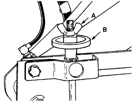
Main brush height adjustment knob
The main brush height adjustment knob is located behind an access door next to the operator’s left foot. It limits how close to the ground the main brush will operate when the main brush position lever is in the “normal” position.
To raise the main brush and reduce the main brush floor contact, loosen the wing nut and thread the knob clockwise.
To lower the main brush and increase main brush floor contact, loosen the locking knob and thread the knob counter-clockwise. Retighten the wing nut after making any adjustment.
Instrument panel
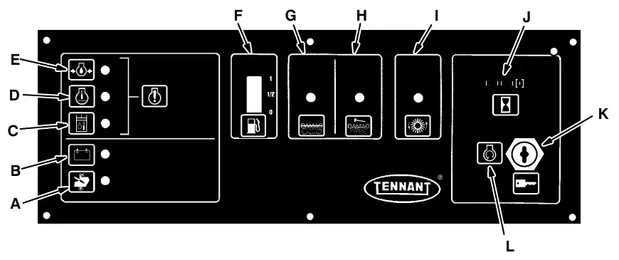
| Letter | Item | Letter | Item |
|---|---|---|---|
| A | Thermal Sentry™ Indicator | F | Fuel Level Gauge |
| B | Battery Condition Indicator | G | Clogged Filter Indicator |
| C | Hydraulic Fluid Temperature Indicator | H | Filter Shaker Switch |
| D | Engine Coolant Temperature Indicator | I | Main Brush and Vacuum Fan Switch |
| E | Engine Oil Pressure Indicator | J | Engine Hour Meter |
| K | Ignition Switch | ||
| L | Start Switch |
Thermal Sentry™ indicator
The Thermal Sentry™ indicator glows when there is excessive heat, possibly from a fire, in the hopper. It will stop the vacuum fan and main brush from operating. The Thermal Sentry™ must be manually reset. See THERMAL SENTRY™ in the MAINTENANCE section.
Battery condition indicator
The battery condition indicator glows when the present voltage potential of the battery is not normal – 10 to 14 volts. Also when the engine is operating, the indicator glows when the alternator output voltage falls below 10 volts or when it exceeds 14 volts. If the voltage falls below 10 volts, it may not be accepting or getting a charge from the alternator. If the voltage exceeds 14 volts, it may be overcharging. Undercharging and overcharging are indications that one or more electrical components are in need of repair.
Hydraulic fluid temperature indicator
The hydraulic fluid temperature indicator glows when the temperature of the hydraulic fluid in the reservoir exceeds 225° F (107° C). When the indicator glows, an audio alarm will sound for 30 seconds and then the engine will stop. The engine may be restarted – the alarm may still sound. If it does, you will have another 30 seconds before the engine stops. Locate and correct the problem.
Engine coolant temperature indicator
The engine coolant temperature indicator glows when the temperature of the engine coolant exceeds 225° F (107° C). When the indicator glows, an audio alarm will sound for 30 seconds and then the engine will stop. The engine may be restarted – the alarm may still sound. If it does, you will have another 30 seconds before the engine stops. Locate and correct the problem.
An over-heating condition may arise due to a low coolant level, a clogged radiator, a loose fan belt, a defective thermostat, or other engine malfunctions. Engine over-heating will always cause a coolant loss. If coolant loss does not occur, check for malfunction of the temperature sending unit.
Engine oil pressure indicator
The engine oil pressure indicator glows when the engine oil pressure falls below 5 psi (35 kPa). When the indicator glows, an audio alarm will sound for 30 seconds and then the engine will stop. The engine may be restarted – the alarm may still sound. If it does, you will have another 30 seconds before the engine stops. Locate and correct the problem.
Fuel level gauge
The fuel level gauge indicates how much fuel is left in the fuel tank. It is present on gasoline and diesel powered machines.
Clogged filter indicator
The clogged filter indicator glows when the hopper dust filter is clogged.
To unclog the filter, shake it with the filter shaker switch. If the filter shaker does not clean the filter enough to turn the indicator off, clean the filter as described in HOPPER DUST FILTER in the MAINTENANCE section.
Filter shaker switch
The filter shaker switch operates the hopper dust filter shaker.
To unclog the hopper dust filter, push the filter shaker switch. The filter shaker motor will then operate for 30 seconds. If the filter shaker does not clean the filter enough to keep the clogged indicator off, try it again. Then if the filter shaker does not clean the filter enough to keep the indicator off, clean the filter as described in HOPPER DUST FILTER in the MAINTENANCE section.
Main brush and vacuum fan switch
The main brush and vacuum fan switch controls hydraulic fluid flow to the main brush and vacuum fan motors. The switch also controls the scrub attachment, and the snow broom motor (only) when the machine is equipped with the snow broom accessory.
To start main brush rotation and vacuum fan suction, press the switch.
To stop main brush rotation and vacuum fan suction, press the switch again.
Engine hour meter
The engine hour meter records the number of hours the machine has been operated. This information is useful in determining when to service the machine.
Ignition and start switches
The key-operated ignition switch controls power to all machine electrical components. The start switch operates the engine starter motor.
To start the engine, turn the key fully clockwise. Then press and hold the start switch until the engine starts.
NOTE: Do not operate the starter motor for more than 10 seconds at a time or after the engine has started. Allow the starter to cool between starting attempts. The starter may be damaged if it is operated incorrectly.
To stop the engine, turn the key counter-clockwise.
Side brush position lever
The side position lever controls the position of the side brush.
To lower the side brush, pull the lever back and to the left into the (Side Brush Down) position. To raise the side brush, pull the level back and to the right into the (Side Brush Up) position.
NOTE: Always raise the side brush when the machine is not being operated for a period of time to prevent the side brush from taking a set.
Hopper support bar
The hopper support bar is located on the operator’s side of the hopper. It holds the hopper in a “raised” position to allow work to be done under the hopper. Do not rely on the machine hydraulic system to keep the hopper raised.
To engage hopper support bar
- Set the machine parking brake and start the engine.
FOR SAFETY: Before leaving or servicing the machine; stop on level surface, set parking brake, and turn off machine.
- Raise the hopper to the fully raised position.
- Lift and position the hopper support bar under the hopper lift arm pin on low dump models, or hopper lift arm cam on multi-level dump models.
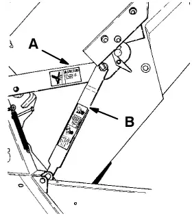
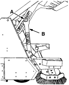
- Slowly lower the hopper so the lift arm pin or cam rests on the support bar.
- Turn the engine off.
- Check the support bar to make sure it is securely engaged.
To disengage hopper support bar
- Start the engine.
- Raise the hopper to the fully raised position.
- Place the support bar in its storage position.
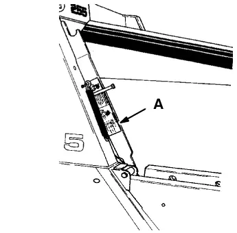
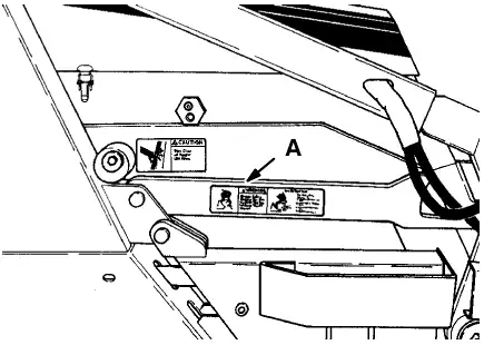
- Lower the hopper.
- Turn the engine off.
Scrub brush position lever
The scrub brush position lever is located on the right side of the scrub attachment. The lever controls the position of the scrub brush.
The scrub brush may be positioned in either the raised, normal, or restricted down positions. The raised position is used when the scrub attachment is not in use. The normal position is for general scrubbing. The restricted down position is used to remove compacted soilage.
To raise the scrub brush, pull the lever back and to the right into the raised position.
To lower the scrub brush, pull the lever back and lower it into the normal position or push it forward into the restricted down position.
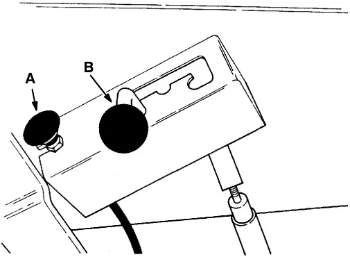
Solution flow knob
The solution flow knob controls the solution flow rate to the floor. The solution flow switch is used to start and stop solution flow.
To increase solution flow, pull the knob out. To decrease solution flow, push the knob in. Pushing the knob all of the way in will stop solution flow.
Circuit breakers and relays
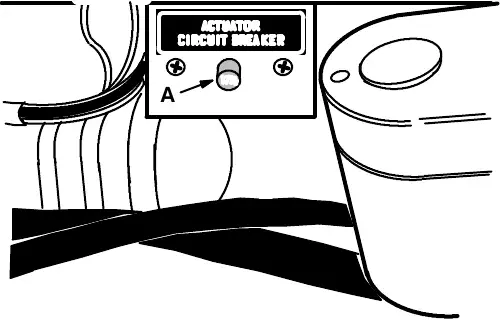
Circuit breakers are resetable circuit protection devices designed to stop the flow of current in the event of a circuit overload. Once tripped, circuit breakers must be allowed to cool and then manually reset. If the overload which caused the circuit breaker to trip is still present in the circuit, the circuit breaker will continue to stop current flow until the overload is corrected.
The circuit breakers are located on the lintel, under the engine cover.
Also included in the machine electrical system are relays that work with the electronic instrument panel. They are located on the lintel in front of the instrument panel.
The following chart shows the various circuit breakers and the electrical components they protect. It also shows the relays and the circuits they control.
| Protective device | Rating | Circuit protected |
|---|---|---|
| CB-1 | 15 A | Filter Shaker |
| CB-2 | 15 A | Horn |
| CB-3 | 15 A | Engine Ignition |
| CB-4 | 15 A | Operating Lights, Scrub Attachment |
| CB-5 | 15 A | Hazard Light, Cab |
| CB-6 | 17.5 A | Squeegee Actuator |
| CB-7 | 17.5 A | Squeegee Actuator |
| M-1 | – | Starter |
| M-2 | – | Fuel pump, Ignition |
| M-3 | – | Starter |
| M-4 | – | Main Brush |
| M-5 | – | Filter Shaker |
| M-6 | – | Horn |
Machine operation
Normal sweeping operation
A normal sweeping operation consists of seven typical operations: pre-start checklist, starting machine, sweeping, dumping hopper, post operation checklist – engine operating, stopping machine, and post operation checklist – engine stopped.
PRE-START CHECKLIST lists things to check before starting the machine.
TO START MACHINE lists the steps required to start the machine.
TO SWEEP lists things to keep in mind before and during the sweeping operation.
TO DUMP HOPPER lists the steps required to dump the hopper.
POST OPERATION CHECKLIST – ENGINE OPERATING lists things to check before stopping the machine engine.
TO STOP MACHINE lists the steps required to stop the machine.
POST OPERATION CHECKLIST – ENGINE STOPPED lists things to check after stopping the machine engine.
Pre-start checklist
- Check under machine for leak spots.
- Empty the engine air filter dust cap and check the air filter restriction indicator.
- Check the engine radiator for debris and clean if needed.
- Check the brushes and brush skirts for damage, wear and adjustment.
- Check engine lubricating oil level.
- Check fuel level.
- Check for LPG odor indicating a fuel leak.
- Check brakes and controls for proper operation.
- Check service records to determine service requirements.
To start machine
NOTE: Before starting machine, perform the pre-start checks.
- LPG powered machines: Slowly open the liquid service valve.
NOTE: Opening the service valve too quickly may cause the service valve check valve to stop the flow of LPG fuel. If the check valve stops the flow of fuel, close the valve, wait a few seconds, and slowly open the valve once again.
Diesel powered machines: Push the diesel preheat pushbutton until the preheat indicator glows brightly.
- The machine operator must be in the operator’s seat with the directional pedal in the “neutral” position and with a foot on the brake pedal or with the parking brake engaged.
FOR SAFETY: Before starting machine make sure all safety devices are in place and operate properly.
- Gasoline powered machines: When the engine is cold, pull out the choke knob about three-fourths of the way. Push the choke in after the engine is running smoothly.
LPG powered machines: When the engine is cold and exposed to cold temperatures, open the engine cover, press the primer button on the LPG vaporizer, close the engine cover.
- Place the throttle control in the (Idle) position.
- Turn the ignition switch key clockwise. Press the start switch until the engine starts. Do not operate the starter for more than a few seconds at a time or after the engine has started.
NOTE: Do not operate the starter motor for more than 10 seconds at a time or after the engine has started. Allow the starter to cool between starting attempts. The starter motor may be damaged if it is operated incorrectly.
To start machine (continued)
- Allow the engine and hydraulic system to warm up three to five minutes.
- Release the machine parking brake.
- Place the throttle control in the (Fast 1) position, and drive the machine to the area to be swept.
To sweep
Plan the sweeping in advance. Try to arrange long runs with minimum stopping and starting. Sweep debris from very narrow aisles into main aisles ahead of time. Do an entire floor or section at one time.
Pick up oversize debris before sweeping. Flatten or remove bulky cartons from aisles before sweeping. Pick up pieces of wire, twine, string, etc., which could become entangled in brush or brush plugs. Overlap brush paths.
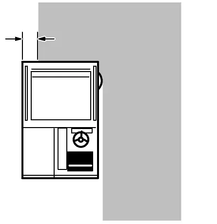
Avoid turning the steering wheel too sharply when the machine is in motion. The machine is very responsive to the movement of the steering wheel. Avoid sudden turns, except in emergencies.
Sweep as straight a path as possible. Avoid bumping into posts or scraping the sides of the sweeper.
Speed up the engine from (Fast 1) to (Fast 2) when light litter is to be picked up. This will improve both litter pickup and hopper loading. Do not overuse the (Fast 2) speed as the machine may dust and clog the hopper filters in dusty environments. Normal debris is best picked up with the engine operating in the (Fast 1) position.
- Push the hopper lift and side brush lever into the (Side Brush On) position.
- Press the main brush and vacuum fan switch to start the main brush and vacuum fan.
- Move the main bush position lever into the (Main Brush Down) position and the side brush position lever into the (Side Brush Down) position.
- Sweep as required.
To dump hopper
- Pull the main brush position lever back into the (Main Brush Up) position.
- Pull the side brush position lever back into the (Side Brush Up) position.
- Press the main brush and vacuum fan switch to stop the main brush and vacuum fan.
- Press the filter shaker switch.
- Slowly drive the machine up to the dump site or dumpster.
- Low dump model machines: Pull the hopper lift and side brush lever back into the (Hopper Up) position to dump the hopper. Pull the lever into the (Hopper Hold) position to keep the hopper in the dumped position.
Multi-level dump model machines: Pull the hopper lift and side brush lever back into the (Hopper Up) position to lift the hopper to the desired height. Be aware, the minimum vertical clearance needed to high dump the hopper 108 in (2745 mm).
WARNING: Machine hopper lifts to 108 in (2745 mm) when high dumping. Hopper can hit overhead wires or object. Electrical shock or falling debris can result. Be sure adequate clearance is available before raising hopper.Multi-level dump model machines: Pull the hopper lift and side brush lever back into the (Hopper Hold) position to keep the hopper at the desired height; then push the hopper dump lever into the (Hopper Roll Out) position to dump the hopper.
NOTE: Lowering the hopper into the dumpster may help to control flying dust.
Multi-level dump model machines: Pull the hopper dump lever into the (Hopper Roll In) position to return the hopper to its normal angle, then release the lever.
- Push the hopper lift and side brush lever into the (Hopper Down) position to return the hopper to its operating position.
- Slowly back the machine away from the dump site or dumpster.
Post operation checklist – engine operating
- Check brush patterns for width and evenness.
To stop machine
- Return the directional pedal to the “neutral” position. Apply the brake.
- Pull the main brush position lever into the (Main Brush Up) position and the side brush position lever into the (Side Brush Up) position.
- Place the hopper lift and side brush lever into the (Hopper Down) position.
- Press the main brush and vacuum fan switch to stop the main brush and vacuum fan.
- Turn the operating lights off if used.
- Gasoline and LPG powered machines: Place the throttle control in the (Idle) position.
Diesel powered machines: Place the throttle lever in the (Diesel Stop) position.
- Set the machine parking brake.
- Turn the ignition switch key counter-clockwise. Remove the key.
FOR SAFETY: Before leaving or servicing the machine; stop on level surface, set parking brake, and turn off machine.
- LPG powered machines: Close the LPG tank liquid service valve.
Post operation checklist – engine stopped
- Check skirts for damage, wear, and adjustment.
- Check for wire or string tangled on brushes.
- Check to make sure LPG tank service valve is closed.
- Check for LPG odor indicating a fuel leak.
- Check under machine for leak spots.
Normal scrubbing operation
A normal scrubbing operation consists of seven typical operations: pre-start checklist, starting machine, scrubbing, draining recovery tank and emptying hopper, post operation checklist – engine operating, stopping machine, and post operation checklist – engine stopped.
PRE-START CHECKLIST lists things to check before starting the machine.
TO START MACHINE lists the steps required to start the machine.
TO SCRUB lists things to keep in mind before and during the scrubbing operation.
TO DRAIN RECOVERY TANK AND EMPTY HOPPER lists the steps required to empty the debris hopper and the recovery tank.
POST OPERATION CHECKLIST – ENGINE OPERATING lists things to check before stopping the machine engine.
TO STOP MACHINE lists the steps required to stop the machine.
POST OPERATION CHECKLIST – ENGINE STOPPED lists things to check after stopping the machine engine.
Pre-start checklist
- Check under machine for leak spots.
- Empty the engine air filter dust cap and check the air filter restriction indicator.
- Check the engine radiator for debris and clean if needed.
- Check the brushes and brush skirts for damage, wear and adjustment.
- Check engine lubricating oil level.
- Check fuel level.
- Check for LPG odor indicating a fuel leak.
- Check brakes and controls for proper operation.
- Check service records to determine service requirements.
To start machine
NOTE: Before starting machine, perform the pre-start checks.
- LPG powered machines: Slowly open the liquid service valve.
NOTE: Opening the service valve too quickly may cause the service valve check valve to stop the flow of LPG fuel. If the check valve stops the flow of fuel, close the valve, wait a few seconds, and slowly open the valve once again.
Diesel powered machines: Push the diesel preheat pushbutton until the preheat indicator glows brightly.
- The machine operator must be in the operator’s seat with the directional pedal in the “neutral” position and with a foot on the brake pedal or with the parking brake set.
FOR SAFETY: Before leaving or servicing the machine; stop on level surface, set parking brake, and turn off machine.
- Gasoline powered machines: When the engine is cold, pull out the choke knob about three-fourths of the way. Push choke in after the engine is running smoothly.
LPG powered machines: When the engine is cold and exposed to cold temperatures, open the engine cover, press the primer button on the LPG vaporizer, close the engine cover.
- Place throttle control in the (Idle) position.
- Turn the ignition switch key clockwise. Press the start switch until the engine starts. Do not operate the starter for more than a few seconds at a time or after the engine has started.
NOTE: Do not operate the starter motor for more than 10 seconds at a time or after the engine has started. Allow the starter to cool between starting attempts. The starter motor may be damaged if it is operated incorrectly.
- Allow the engine and hydraulic system to warm up three to five minutes.
- Disengage the machine parking brake.
- Place the throttle control in the (Fast 1) position and drive the machine to the solution filling site.
To scrub
Plan the scrubbing in advance. Try to arrange long runs with minimum stopping and starting. Do an entire floor or section at one time.
Pick up oversize debris before scrubbing. Remove bulky debris from aisles before scrubbing. Pick up pieces of wire, twine, string, etc., which could become entangled in brush or brush plugs.
Allow a few inches overlap of brush paths.
Do not turn steering wheel too sharply when the machine is in motion. It is very responsive to the movement of the steering wheel. Avoid sudden turns, except in emergencies.
Try to scrub as straight a path as possible. Avoid bumping into posts or scraping the sides of the machine.
Floor conditions, amount of soilage, type of soilage, brush action, and squeegee action all play an important role in determining the type and concentration of detergent to be used. For specific recommendations, consult the local Tennant Company Representative.
The recovery tank should be drained after the solution tank is empty and whenever the ball float rises and stops water vacuum. The recovery tank may fill before the solution tank empties if standing water is picked up in addition to the solution put down by the machine.
For best scrubbing results, reduce speed to one-half maximum machine speed. Shut off solution flow to floor 5 ft (1525 mm) before making turns. Adjust solution flow to floor with solution flow knob to match floor conditions.
Always raise the rear squeegee before backing machine.
- Stop the engine and set the parking brake before filling solution tanks.
FOR SAFETY: Before leaving or servicing the machine; stop on level surface, set parking brake, and turn off machine.
- Open the solution tank covers.
- Pour the required amount of detergent into the solution tanks. Fill the tanks with water.
- Start and drive the machine to the area to be scrubbed.
- Push the hopper lift and side brush lever into the (Side Brush On) position.
- Press the main brush and vacuum fan switch to start the main brush, scrub brush, and vacuum fan.
- Move the main brush position lever into the (Main Brush Down) position, and the scrub brush position lever into the normal position. Move the side brush position lever into the (Side Brush Down) position.
- Place the water valve switch in the top position.
- Place the throttle control in the (Fast 2) position.
- Place the squeegee switch in the bottom (Squeegee Down) position.
- Scrub as required. Adjust the solution flow to match floor conditions. When the recovery tank ball float stops vacuum, return to the solution dump/filling site. Drain the recovery tank, empty the hopper, and refill the solution tank.
To drain recovery tank and empty debris hopper
- Place the water valve switch in the bottom position.
- Pull the main brush into the (Main Brush Up) position, and the scrub brush position lever into the raise position. Move the side brush position lever into the (Side Brush Up) position.
- Move the hopper lift and side brush lever to the (Hopper Down) position to stop the side brush rotation.
- Press the main brush and vacuum fan switch to stop the main brush, scrub brush, and vacuum fan.
- Place the squeegee switch in the top (Squeegee Up) position.
- Park the machine next to a floor drain. Stop the engine and set the parking brake.
FOR SAFETY: Before leaving or servicing the machine; stop on level surface, set parking brake, and turn off machine.
- Open the front access door.
- Remove the tank drain hose from its retention plug. Lower the hose to the floor drain to drain the tank.
NOTE: The tank will not empty with the vacuum fan operating.
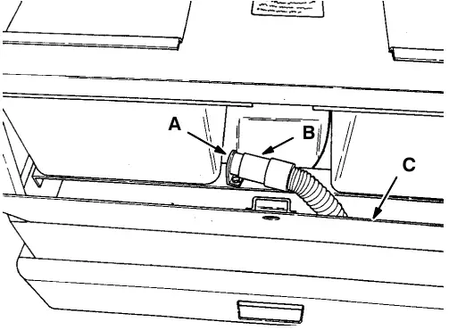
- Replace the hose on the retention plug after the tank is empty.
- Close the front access door.
- Start the engine and move the hopper lift and side brush lever to the (Hopper Up) position to empty the debris hopper.
- Move the hopper lift and side brush lever to the (Hopper Down) position to lower the scrub attachment
Post operation checklist – engine operating
- Check scrub brush pattern for width and evenness.
- Check squeegees for proper deflection.
To stop machine
- Return the directional pedal to the “neutral” position. Apply the brake.
- Place the water valve switch in the bottom position.
- Pull the main brush position lever into the (Main Brush Up) position, and the scrub brush position lever in the raise position. Move the side brush position lever into the (Side Brush Up) position.
- Move the hopper lift and side brush lever to the (Hopper Down) position to stop the side brush rotation.
- Press the main brush and vacuum fan switch to the stop the main brush, scrub brush, and vacuum fan.
- Place the squeegee switch in the top (Squeegee Up) position.
- Turn the operating lights off if used.
- Gasoline and LPG powered machines: Place the throttle control in the (Idle) position.
Diesel powered machines: Place the throttle control in the (Diesel Off) position.
- Set the machine parking brake.
- Turn the ignition switch key counter-clockwise. Remove the key.
FOR SAFETY: Before leaving or servicing the machine; stop on level surface, set parking brake, and turn off machine.
- LPG powered machines: Close the LPG tank liquid service valve.
Post operation checklist – engine stopped
- Check skirts for damage, wear, and adjustment.
- Check for wire or string tangled on brushes.
- Drain and clean recovery tank.
- Check vacuum hoses for debris or obstructions.
- Check to make sure LPG tank service valve is closed.
- Check for LPG odor indicating a fuel leak.
- Check under machine for leak spots.
Double scrubbing operation
Double scrubbing is a method of removing heavy accumulations of soilage, dirt, wax, or spills. It involves making two passes over the area to be cleaned. To double scrub, make a single pass over the surface being cleaned with the rear squeegee raised. Allow the solution to soak on the floor for 15 to 20 minutes. Then make a second scrubbing pass in the normal manner with the rear squeegee lowered.
Operation on grades
Drive the machine slowly on grades. Use the service brakes to control machine speed.
The maximum rate ramp climb and descent angle is 15° with an empty hopper, and 10° with a full hopper.
Vacuum wand
The vacuum wand accessory gives the machine the added flexibility of picking up debris not accessible by the machine. A 120 in (3050 mm) hose utilizes the machine vacuum system.
To operate vacuum wand
- Stop the machine close to the area to be cleaned.
- Move the main brush position lever into the (Main Brush Up) position. Move the side brush position lever to the (Side Brush Up) position.
- Stop the engine and set the machine parking brake.
FOR SAFETY: Before leaving or servicing the machine; stop on level surface, set parking brake, and turn off machine.
- Open the hopper inspection door.
- Low dump models: Unlatch the vacuum door retainer. Press the vacuum door arms down to close the vacuum door.
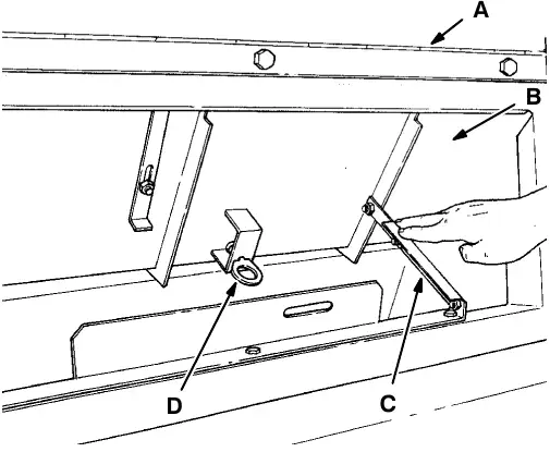
Closing vacuum door (02749). A. Inspection Door. B. Vacuum Door. C. Door Arm. D. Retainer. Multi-level dump models: Push the vacuum door closed. Press the vacuum door arms down to lock the door shut.
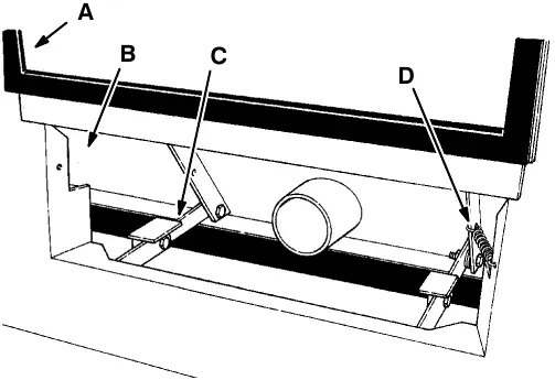
Closed vacuum door (02801). A. Inspection Door. B. Vacuum Door. C. Door Arm. D. Spring. - Low dump models: Remove the vacuum plug from the side of the hopper.
- Assemble the vacuum wand to the vacuum hose.
- Connect the hose to the vacuum connection.
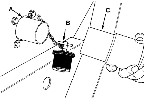
Connecting vacuum hose – low dump model (02750). A. Vacuum Connection. B. Vacuum Plug. C. Hose. - Start the engine and move the throttle control to the (Fast 1) position.
- Press the main brush and vacuum fan switch to start the vacuum fan.
To operate vacuum wand (continued)
- Vacuum the area as required.
- When finished, press the main brush and vacuum fan switch to stop the vacuum fan; then stop the engine.
- Disassemble the vacuum wand and hose. Place them in their storage locations.
- Low dump models: Replug the vacuum connection.
- Pull the vacuum door arms up to open the vacuum door.
- Low dump models: Pull the door retainer through the door brackets and latch to hold the vacuum door open.
Multi-level dump models: Pull the vacuum door open. The spring will keep the door open.
- Close the hopper inspection door.
Hopper dolly
The hopper dolly accessory makes the job of removing the low dump model debris hopper easy. It also is used to store the hopper when it is not mounted on the machine.
To remove hopper with dolly
- Empty debris hopper.
- Stop the engine and set the machine parking brake.
FOR SAFETY: Before leaving or servicing the machine; stop on level surface, set parking brake, and turn off machine.
- Unlatch and remove the hopper cover.
- Disconnect all wires and vacuum hoses between the hopper and the machine.
- Reposition and latch the hopper cover on the hopper.
- Start the engine, raise the hopper, and place the hopper lift and side brush lever in the (Hopper Hold) position.
- Stop the engine.
- Roll the hopper dolly under the hopper so the lip on the short end of the dolly is behind the bottom edge of the hopper.
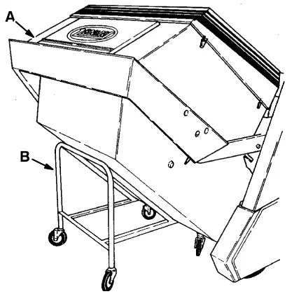
Hopper dolly (02751). A. Hopper. B. Dolly. - Tilt the lift arm hooks back away from the lift arm pins.
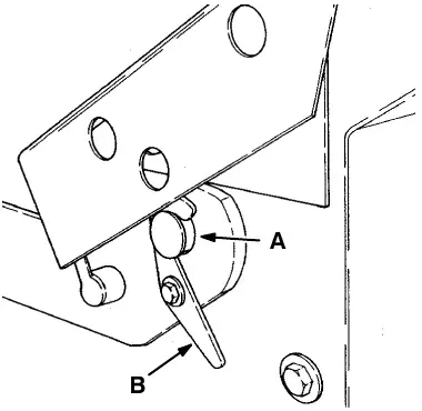
Lift arm hook (02752). A. Pin. B. Hook. - Place the hopper lift and side brush lever in the (Hopper Down) position to lower the hopper onto the dolly.
- Push the lift arms down to clear the lift arm pins and roll the hopper away from the machine.
To install hopper with dolly
- Stop the engine and set the machine parking brake.
FOR SAFETY: Before leaving or servicing the machine; stop on level surface, set parking brake, and turn off machine.
- Roll the hopper into position in the machine.
- Position the lift arm pins in the lift arm slots. Push the lift arm hooks over the pins.
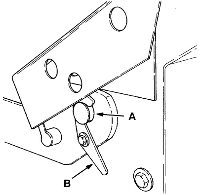
Lift arm hook (02752). A. Pin. B. Hook. - Start the engine, raise the hopper, and place the hopper lift and side brush lever in the (Hopper Hold) position.
- Stop the engine.
- Roll the hopper dolly away from the machine.
- Place the hopper lift and side brush lever in the (Hopper Down) position.
- Unlatch and remove the hopper cover.
- Connect the wire harness connectors and the vacuum hose(s) between the hopper and the machine.
- Reposition and latch the hopper cover on the hopper.
Scrub attachment
The scrub attachment accessory gives the machine the added flexibility to scrub floors. It consists of three groups of parts – the scrub attachment, the side scrub brush and squeegee, and the rear squeegee.
The scrub attachment and side scrub brush and squeegee are to be removed when sweeping. The rear squeegee may be left on the machine in the “raised” position. The scrub attachment takes the place of the sweeping hopper. The side scrub brush and squeegee take the place of the side sweep brush. The main sweeping brush is also exchanged for a scrubbing variety brush in the conversion.
To mount scrub attachment
- Remove debris hopper with hopper dolly as described in TO REMOVE HOPPER WITH DOLLY.
- Stop the engine and set the machine parking brake.
FOR SAFETY: Before leaving or servicing the machine; stop on level surface, set parking brake, and turn off machine.
- Position top lift arm cams vertically.
- Position the scrub attachment rear left cam locking bracket in the “top” position.
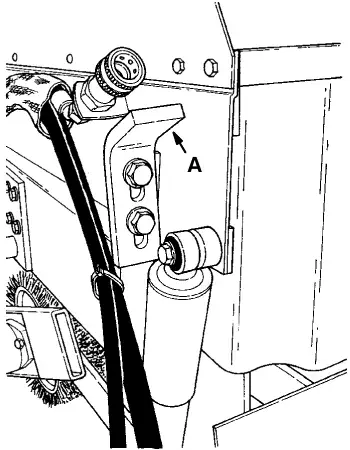
Locking bracket (02756). A. Locking Bracket.
To mount scrub attachment (continued)
- Roll the scrub attachment into position in the machine until it contacts bottom lift arm cams.
WARNING: The solution and recovery tanks must be empty during scrub attachment installation and removal to avoid personal injury.
- Position the lift arm pins in the lift arm slots. Push the lift arm hooks over the pins.
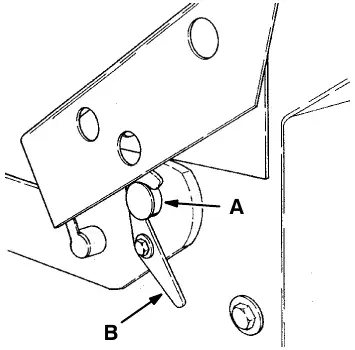
Lift arm hook (02752). A. Pin. B. Hook. - Turn the top lift arm cams, one on each side, so they overlap the scrub attachment brackets. Tighten the cam bolts. Be aware that the left side cam bolt has left hand threads.
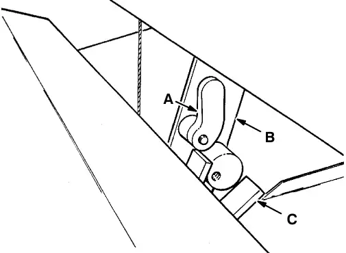
Top lift arm cam (02753). A. Top Cam. B. Lift Arm. C. Bracket. - Start the engine, raise the scrub attachment, and engage the hopper support bar. Stop the engine.
WARNING: Falling hopper. Engage hopper support bar before working under hopper.
- Pull the scrub attachment leg locking knobs out, swing the legs up into the “raised” position, and release the knobs.
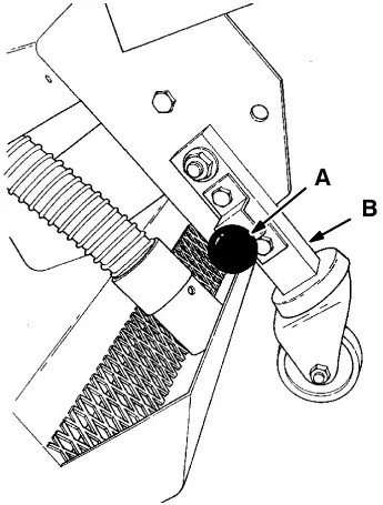
Scrub attachment leg (02754). A. Locking Knob. B. Leg. - Start the engine, raise the scrub attachment, place the hopper support bar in its storage location, and lower the scrub attachment. Stop the engine.
- Push the rear of the scrub attachment down so the right side cam locking bracket contacts the bottom lift arm cam. Snug the top lift arm cam up to the locking bracket and tighten the cam bolt.
- Push the rear of the scrub attachment down so the left side cam locking bracket contacts the bottom lift arm cam. Snug the top lift arm cam up to the locking bracket and tighten the left-hand threaded cam bolt.
- Connect the wire harness connectors and vacuum hoses between the scrub attachment and the machine.
To mount scrub attachment (continued)
- Disconnect the hydraulic hose from the front of the quick-disconnect station and connect it to the quick-disconnect fitting mounted on the scrub attachment.
NOTE: Wipe all dirt and oil from couplings before making connections to avoid hydraulic system contamination.
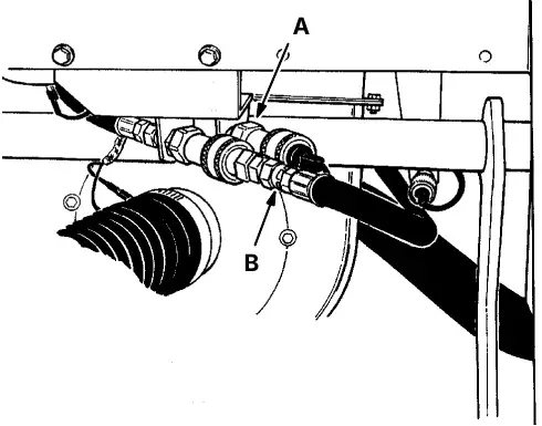
Quick-disconnect station (02755). A. Quick-Disconnect Station. B. Hydraulic Hose. 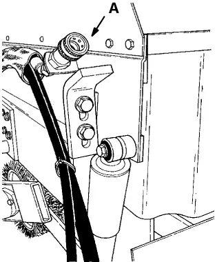
Scrub attachment quick-disconnect fitting (02756). A. Quick-Disconnect Fitting. - Connect the large diameter hose from the scrub attachment to the quick-disconnect station port the previous hose was connected to.
- Connect the small diameter hose from the scrub attachment to the quick-disconnect fitting below the quick-disconnect station.
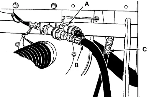
Connected scrub attachment hoses (02810). A. Quick-Disconnect Station. B. Large Diameter Hose. C. Small Diameter Hose. - Slide the side brush squeegee assembly into position in the squeegee bracket.
- Slide the two squeegee retaining pins through the bracket and squeegee assembly.
- Pull the pin keeper out, turn the squeegee retaining pins so they are under the pin keeper, and release the keeper.
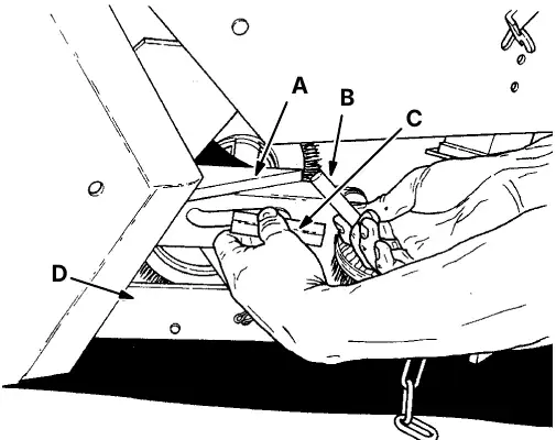
Securing squeegee retaining pins (02757). A. Bracket. B. Retaining Pin. C. Pin Keeper. D. Squeegee Assembly.
To mount scrub attachment (continued)
- Connect the squeegee assembly chain to the chain hook.
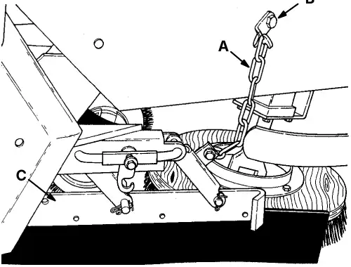
Squeegee assembly chain (02758). A. Chain. B. Hook. C. Squeegee Assembly. - Replace the side brush with a scrubbing side brush as described in TO REPLACE SIDE BRUSH.
- Replace the main brush with a scrubbing main brush as described in TO REPLACE MAIN BRUSH.
- Check the rear tire pressure. It should be 70 ± 5 psi (480 ± 35 kPa) for scrubbing.
- Check the air bleed hole on the rear squeegee pickup hose. The hole should be on the side of the hose next to the squeegee nozzle. The hole should be free of debris or obstructions.
To remove scrub attachment
- Drain the scrub attachment solution and recovery tanks.
WARNING: The solution and recovery tanks must be empty during scrub attachment installation and removal to avoid personal injury.
- Drive the machine to the scrub attachment storage area.
- Disconnect the squeegee assembly chain from the chain hook.
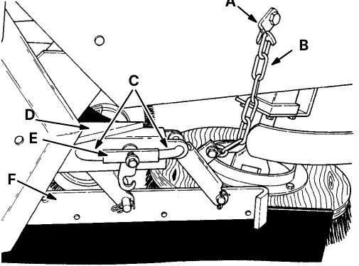
Squeegee assembly (02758). A. Hook. B. Chain. C. Retaining Pin. D. Bracket. E. Pin Keeper. F. Squeegee Assembly. - Pull the retaining pin keeper out and remove the two squeegee assembly retaining pins. Release the pin keeper.
To remove scrub attachment (continued)
- Slide the squeegee assembly out from the machine.
- Disconnect the small diameter hose from the quick-disconnect coupling on the machine. Replace the coupling plug.
NOTE: Wipe all dirt and oil from couplings before making connections to avoid hydraulic system contamination.
- Disconnect the large diameter hose from the quick-disconnect station.
- Disconnect the large diameter hose from the quick-disconnect coupling on the side of the scrub attachment. Reconnect it to the operator-side port of the quick-disconnect station.
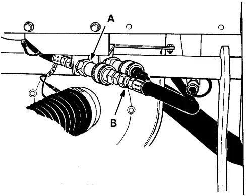
Reconnected hose (02755). A. Operator-Side Port. B. Hydraulic Hose. - Disconnect the wire harness connectors and vacuum hoses between the scrub attachment and the machine.
- Start the engine, raise the scrub attachment, and engage the hopper support bar. Stop the engine.
WARNING: Falling hopper. Engage hopper support bar before working under hopper.
- Pull the scrub attachment leg locking knobs out, swing the legs down into the “down” position, and release the knobs.
- Start the engine, raise the scrub attachment, place the hopper support bar in its storage location, and lower the scrub attachment. Stop the engine.
- Loosen the top lift arm cam bolts, one on each side, to free scrub attachment.
- Tilt the lift arm hooks back away from the lift arm pins.
- Push the lift arms down to clear the lift arm pins.
- Roll the scrub attachment out of the machine to its storage location.
- Replace the side scrub brush with a sweeping variety side brush as described in TO REPLACE SIDE BRUSH.
- Replace the main brush with a sweeping variety main brush as described in TO REPLACE MAIN BRUSH.
- Check the rear tire pressure. It should be 80 ± 5 psi (550 ± 35 kPa) for sweeping.
Snow blade
The snow blade accessory gives the machine the added flexibility to remove snow from walks and driveways. It consists of two groups of parts – the mounting frame and the blade assembly. The mounting frame is used to mount either the snow blade or snow broom assembly to the machine. The blade assembly may be positioned to push snow straight ahead, to the left, or to the right of the machine at various angles.
To install snow blade
- Remove hopper as described in TO REMOVE HOPPER WITH DOLLY.
- Raise and chain up the front bumper, if present, and the side brush arm.
- Position the blade mounting frame lift pins in the lift arm slots. Push the lift arm hooks over the pins.
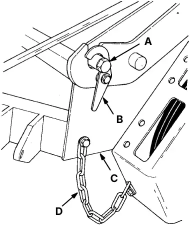
Lift arm hook (02759). A. Pin. B. Hook. C. Mounting Frame. D. Limiting Chain. - Position the upper ends of the mounting frame over the cams.
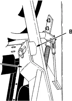
Secure mounting frame upper end (02760). A. Upper End. B. Cam. - Secure each upper end of the mounting frame to the cam with a spacer and bolt provided with the accessory.
- Connect the two limiting chains between the mounting frame and the machine.
- Connect the snow blade quadrant assembly to the mounting frame with the king pin and the sector pin.
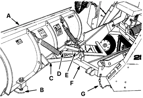
Snow blade installation (02761). A. Snow Blade. B. Runner Spindle. C. Quadrant Assembly. D. King Pin. E. Sector Pin. F. Mounting Frame. G. Limiting Chain (continued on page 52).
Snow blade installation figure key, continued from page 51: G. Limiting Chain.
To operate snow blade
Operate the machine as normally done using the hopper lift and side brush lever to raise and lower the snow blade.
The main brush and side brush should be raised. The main brush and vacuum fan should be off.
Begin plowing early when snow reaches 1 to 4 in (25 to 100 mm). Do not allow snow to accumulate. Heavy, wet snow can create hazards at even a 1 in (25 mm) accumulation. In heavier amounts, snow can be extremely difficult to handle. Do not allow snow to become packed and frozen. Crusted snow can hinder traction in future plowing. Choose the proper plowing speed. The heavier the snow, the slower the speed. The snow blade should be set at the best angle for rolling the snow sideways and in the desired direction. Snow of any considerable depth cannot be pushed straight ahead for more than a short distance.
For best operation, the bottom edge of the snow blade should be slightly above the ground. If adjustments are needed, they can be made by adding flat washers to the runner spindles. Place additional washers under the runner bracket to raise the blade. Remove washers to lower the blade.
To change the angle of the blade, raise the blade as far as the limiting chain will permit. Pull out the sector pin and the blade can be moved to the desired angle. Then replace the sector pin. The sector pin is designed to be a shear pin. If the plow strikes a solid, immovable object, the pin will shear, allowing the blade to swing away from the object before the equipment is damaged. The blade assembly is mounted on the lift arms of the machine which are free to float upward if necessary.
Under some conditions, snow can be pushed to unused areas and stacked to a considerable height. To do this, place the blade in a straight-on position. Push the snow forward by raising the plow as you move into the pile.
Stack snow only with the blade in a straight-on position. Do not create a vertical wall, but slope the piles so that later snow may be pushed up the slope.
Clearing large open areas can be done best by using a combination of snow removal equipment, such as a snow blade and snow blower or loader of some type. The snow can be plowed into windrows or piles and then blown into or loaded onto trucks and carried away. However, if only a blade is available, the area can be cleared by using the proper technique and common sense.
As a guide to help determine how much snow the plow can handle, remember that with a 6 in (150 mm) snowfall, the plow can easily move that amount of snow in two passes. With more snow, it will handle less; with less snow, more.
A suggested method of plowing is as follows:
Make the first pass one blade width in from the outside edge.
Make the second pass around the outside edge, moving the snow to the edge of the area, then keep moving in. Double the blade width from edge of the snow covered area and move this amount to the outside edge.
To remove snow blade
- Drive the machine to the snow blade storage area.
- Stop the engine and set the machine parking brake.
FOR SAFETY: Before leaving or servicing the machine; stop on level surface, set parking brake, and turn off machine.
- Lower the snow blade.
- Disconnect the two limiting chains from the machine frame.
- Remove the upper ends of the mounting frame from the lift arm cams.
- Tilt the lift arm hooks back away from the lift arm pins.
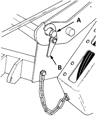
Lift arm hook (02759). A. Pin. B. Hook. - Push the lift arms down to clear the lift arm pins.
- Start the engine, release the parking brake, and back the machine away from the snow blade assembly.
Snow broom
The snow broom accessory gives the machine the added flexibility to remove snow from walks and driveways. It consists of two groups of parts – the mounting frame and the broom frame and drive assembly. The mounting frame is used to mount either the snow blade or snow broom assembly on the machine. The broom frame and drive assembly may be positioned so as to sweep snow to the left or right of the machine. Check the snow broom for tangled string or wire after each use.
To install snow broom assembly
- Remove hopper as described in TO REMOVE HOPPER WITH DOLLY.
- Raise and chain up the front bumper, if present, and the side brush arm.
- Position the broom mounting frame lift pins in the lift arm slots. Push the lift arm hooks over the pins.
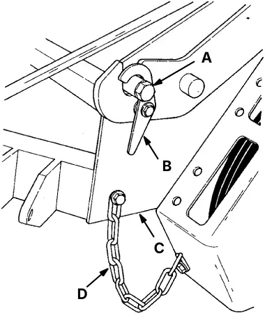
Lift arm hook (02759). A. Pin. B. Hook. C. Mounting Frame. D. Limiting Chain.
To install snow broom assembly (continued)
- Position the upper ends of the mounting frame over the cams.
- Secure each upper end of the mounting frame to the cam with a spacer and bolt provided with the accessory.
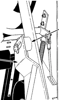
Secured mounting frame upper end (02760). A. Upper End. B. Cam. - Connect the two limiting chains between the mounting frame and the machine.
- Connect the snow broom support arm to the center rear hole in the mounting frame.
- Connect the snow broom frame to either the right or left side of the mounting frame with a clevis pin depending upon which direction the snow should be swept.
- Connect the tension chain between the top of the upright arm and the peg on the support arm. The tension chain helps raise or lower the snow broom.
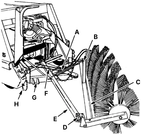
Snow broom installation (02762). A. Tension Chain and Spring. B. Upright Arm. C. Support Arm. D. Clevis Pin. E. Snow Broom Frame. F. Hex Set Screw. G. Mounting Frame. H. Limiting Chain. - Disconnect the hydraulic hose from the front of the quick-disconnect station.
To install snow broom assembly (continued)
- Connect the hoses from the snow broom to the quick-disconnect station ports – upper hose on snow broom to the engine-side port, lower hose to operator-side port.
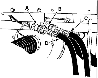
Connected snow broom hoses (02781). A. Operator-Side Port. B. Engine-Side Port. C. Upper Snow Broom Hose. D. Lower Snow Broom Hose. - Measure the distance between the floor surface and the snow broom pivots at the ends of the broom. These two distances should be equal.
To adjust, loosen the mounting frame upper end bolts, reposition the frame, and tighten the bolts. Recheck and adjust as necessary.
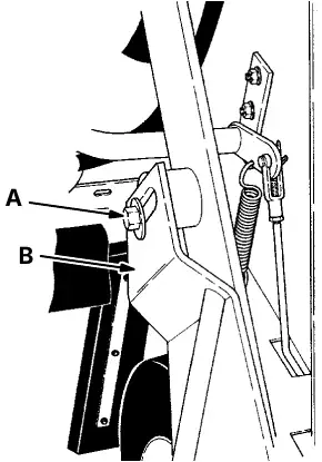
Mounting frame upper end (02760). A. Upper End Bolt. B. Mounting Frame.
To operate snow broom
Operate the machine as normally done using the hopper lift and side brush lever to raise and lower the snow broom. The main brush and side brush should be raised. Press the main brush and vacuum fan switch to operate the snow broom. The main brush and vacuum fan will not operate. The hydraulic fluid normally used to drive them is being diverted to the snow broom.
Begin sweeping early and often. Do not allow snow to accumulate or to become packed and frozen. The snow broom becomes ineffective in snow deeper than 4 in (100 mm).
Slow down in deep snow. Snow is thrown at an angle. The deeper the snow, the steeper the angle. When the snow is deep, it is carried over the top of the broom. Although this snow can be swept, slow down so the broom can catch up.
The brush bristles should contact the surface without being bent under. Adjust the tension chain and spring to control contact. The hex set screw on the support arm can be adjusted to raise or lower the snow broom.
In heavy snow, the broom may stall out. The hydraulic system will bypass the snow broom to protect itself. When this occurs, back the machine away and allow the broom to start rotating again. Do not let the snow broom stall for more than 30 seconds. Stalling causes overheating in the hydraulic system. This can seriously damage the hydraulic system.
To remove snow broom assembly
- Drive the machine to the snow broom storage area.
- Stop the engine and set the machine parking brake.
FOR SAFETY: Before leaving or servicing the machine; stop on level surface, set parking brake, and turn off machine.
- Lower the snow broom.
- Disconnect the hoses from the quick-disconnect station. Replace the coupling caps.
- Reconnect the hose from the machine to the operator-side port of the quick-disconnect station to reengage the main brush motor.
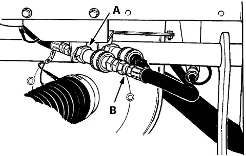
Reconnected hose (02755). A. Operator-Side Port. B. Hydraulic Hose. - Disconnect the two limiting chains from the machine frame.
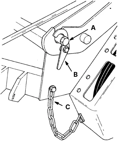
Limiting chain (02759). A. Pin. B. Hook. C. Limiting Chain. - Remove the upper ends of the mounting frame from the lift arm cams.
- Tilt the lift arm hooks back away from the lift arm pins.
- Push the lift arms down to clear the lift arm pins.
- Start the engine, release the parking brake, and back the machine away from the snow broom assembly.
Machine troubleshooting – sweeping
| Problem | Cause | Remedy |
|---|---|---|
| Excessive dusting | Dust skirts and seals worn, damaged, not adjusted properly | Replace or adjust skirts or seals Parts › |
| Dust filter clogged | Shake and/or clean or replace filter Parts › | |
| Engine operating at “litter” speed | Operate engine at “normal” speed | |
| Vacuum wand door closed | Open vacuum wand door | |
| Vacuum hose damaged | Replace vacuum hose Parts › | |
| Vacuum fan failure | See HYDRAULIC SYSTEM TROUBLESHOOTING: Poor or no vacuum to brush compartment | |
| Poor sweeping performance | Brush bristles worn | Replace brushes Parts › |
| Brushes not adjusted properly | Adjust brushes | |
| Debris caught in brush drive mechanism | Free mechanism of debris | |
| Main brush drive failure | See HYDRAULIC SYSTEM TROUBLESHOOTING: Main brush turns slowly or not at all | |
| Side brush drive failure | See HYDRAULIC SYSTEM TROUBLESHOOTING: Side brush turns slowly or not at all | |
| Hopper not adjusted properly | Adjust hopper floor clearance | |
| Hopper full | Empty hopper | |
| Hopper floor skirts worn, damaged | Replace skirts Parts › |
NOTE: For more specific electro-hydraulic system troubleshooting information, see HYDRAULIC SYSTEM TROUBLESHOOTING in the MAINTENANCE section.
Machine troubleshooting – scrubbing
| Problem | Cause | Remedy |
|---|---|---|
| Trailing water – poor or no water pickup | Worn rear squeegee | Rotate or replace rear squeegee blade Parts › |
| Rear squeegee out of adjustment | Adjust rear squeegee | |
| Vacuum hose clogged | Flush vacuum hoses | |
| Recovery tank full | Drain tank | |
| Ball float stuck shutting off vacuum | Clean ball float and float guide | |
| Engine not operating at governed speed (For machines below serial number 010750) | Speed up engine to “litter” speed and readjust governor | |
| Debris caught on squeegee | Remove debris | |
| Debris hopper full | Empty hopper | |
| Foam filling recovery tank | Empty recovery tank; change detergent | |
| Vacuum hose to rear squeegee disconnected or damaged | Reconnect or replace vacuum hose Parts › | |
| Vacuum fan to recovery tank hose damaged | Replace hose Parts › | |
| Little or no solution flow to floor | Solution tank empty | Fill solution tank |
| Water valve cable broken or out of adjustment | Replace and/or adjust cable Parts › | |
| Solution supply lines and spreader tube clogged | Flush solution supply lines, spreader tube | |
| Water valve switch in “off” position | Move switch to “on” position | |
| Water valve solenoid failure | Clean or replace solenoid valve Parts › | |
| Solution flow knob in “off” position | Pull flow knob into “on” position | |
| Poor scrubbing performance | Debris caught on scrub brushes | Remove debris |
| Improper detergent or brushes used | Check with TENNANT® representative for advice | |
| Worn scrub brushes | Replace scrub brushes Parts › | |
| Scrub brushes out of adjustment | Adjust scrub brushes | |
| Scrub brush drive failure | See HYDRAULIC SYSTEM TROUBLESHOOTING: Main brush turns slowly or not at all | |
| Debris hopper full | Empty hopper |
NOTE: For more specific electro-hydraulic system troubleshooting information, see HYDRAULIC SYSTEM TROUBLESHOOTING in the MAINTENANCE section.
Transporting machine
Pushing or towing machine
The machine may be pushed from the front or rear. It may be towed only from the rear.
Place a dolly under the rear wheel to travel distances greater than 1 mile (1 km) or speeds over 1 mph (1 km/h).
Machine jacking
The machine may be jacked up for service at the designated locations. Use a jack of adequate capacity and good working condition. Always stop the machine on a flat, level surface and block the tires before jacking the machine up.
The front jacking locations are on the flat bottom edge of the machine frame next to the front tires.
The rear jacking location is the middle flat bottom edge of the rear bumper.
To jack up machine
- Empty the debris hopper.
- Stop the engine and set the machine parking brake.
FOR SAFETY: Before leaving or servicing the machine; stop on level surface, set parking brake, and turn off machine.
- Block the tires, which are not being jacked up, in order to secure the machine position.
WARNING: Machine is unstable on jack. Block machine tires before jacking machine up.
- Use a jack of adequate capacity to raise the machine. Jack up the machine only at the designated locations.
WARNING: Machine is unstable on jack. Jack machine up at designated locations only. Block machine up with jack stands.
To jack up machine (continued)
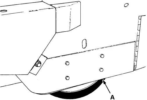
- Block machine up with jack stands or similar devices in the designated locations to secure the machine.
- Lower the machine onto the jack stands.
- Check to make sure the machine is secure.
- Service the machine as required.
- When finished servicing the machine, raise the machine off the jack stands.
- Remove the jack stands from under the machine.
- Lower the machine.
- Remove the blocks from the tires.
Machine tie-downs
The machine may be tied down at each of the corners of the main frame using tie down brackets supplied in the tie-down kit.
When transporting the machine on a trailer or in a truck, be sure to engage the machine parking brake and block the machine tires to prevent the machine from rolling.
Machine storage
Storing machine
When storing the machine for extended periods of time, these procedures must be followed to lessen the chance of rust, sludge, and other undesirable deposits from forming:
- Empty the debris hopper.
- Change engine oil.
- Place the main brush and side brush position levers in the “raise” position.
- Park the machine on a level surface in a cool, dry area.
- Stop the engine and set the machine parking brake.
- Check the hydraulic fluid level. It should be up to the full mark on the dipstick to prevent excessive condensation from forming in the reservoir.
7A. Gasoline and LPG powered machines: To store the machine 30 to 90 days:
- Remove the spark plugs.
- Pour 3 oz (90 cc) of clean engine oil into each spark plug hole.
- Remove the ignition coil high tension wire. Operate the engine starter motor for at least a dozen revolutions. This distributes the oil over the cylinder walls.
NOTE: Before preparing the engine for storage, allow it to cool down to the surrounding temperature. Oil adheres to cold metal surfaces much better than hot surfaces.
- Replace the high tension coil wire and spark plugs.
- Drain the gasoline from the carburetor bowl by removing the carburetor anti-diesel solenoid.
- Replace the carburetor drain plug.
7B. Gasoline and LPG powered machines: To store the machine 90 days to 6 months:
- Remove the spark plugs.
- Pour 3 oz (90 cc) of clean engine oil into each spark plug hole.
- Remove the ignition coil high tension wire. Operate the engine starter for at least a dozen revolutions. This distributes the oil over the cylinder walls.
NOTE: Before preparing the engine for storage, allow it to cool down to the surrounding temperature. Oil adheres to cold metal surfaces much better than hot surfaces.
- Replace the high tension coil wire and spark plugs.
- Drain the engine oil from the engine oil pan.
- Drain the coolant from the radiator and engine block by opening the cooling system drain cocks.
- Close the engine cooling system drain cocks.
- Drain gasoline from the carburetor, fuel tank, and the fuel lines.
- Seal the air cleaner inlet and the exhaust outlet with weatherproof masking tape.
- Tighten the engine oil filler cap, the fuel tank cap, and the radiator cap to make certain they are securely in place.
7C. Diesel powered machines: To store machine:
- Drain the coolant from the radiator and engine block.
- Close the engine cooling system drain cocks.
This page is blank in the printed manual.
Maintenance contents
- Recommended first 50-hour machine inspection (3-3)
- Maintenance chart (3-4)
- Lubrication (3-6)
- Engine (3-6)
- Gasoline and LPG engines (3-6)
- Diesel engines (3-6)
- Steering gear (3-6)
- Rear wheel support (3-6)
- Front wheel bearings (3-6)
- Hopper lift arm pivots (3-7)
- Hopper door latches (3-7)
- Scrub attachment leg casters (3-8)
- Scrub attachment debris hopper (3-8)
- Hydraulics (3-9)
- Hydraulic fluid (3-9)
- Hydraulic fluid reservoir (3-9)
- To drain hydraulic fluid reservoir and replace filter element (3-10)
- To fill hydraulic fluid reservoir (3-11)
- Hydraulic pumps (3-11)
- Directional pedal (3-11)
- To adjust directional pedal (3-12)
- Lift arm speed limiter (3-13)
- Hydraulic fluid leaks (3-13)
- Hydraulic schematic, low dump model (3-14)
- Hydraulic schematic, multi-level dump model (3-15)
- Hydraulic system troubleshooting (3-16)
- Hydraulic components troubleshooting (3-18)
- Engine (3-19)
- Engine lubrication (3-19)
- Gasoline and LPG engines (3-19)
- Diesel engines (3-19)
- Cooling system (3-19)
- Air intake system (3-20)
- Air filter restriction indicator (3-21)
- Air filter (3-21)
- To replace air filter element (3-22)
- Fuel system – gasoline (3-23)
- Fuel filter (3-23)
- Carburetor (3-23)
- Fuel system – LPG (3-24)
- LPG fuel system (3-24)
- Fuel tanks (3-25)
- To change an LPG fuel tank (3-26)
- Fuel filter lock (3-26)
- Vaporizer-regulator (3-26)
- Carburetor (3-26)
- Oil pressure switch (3-26)
- LPG fuel troubleshooting (3-27)
- Fuel system – diesel (3-28)
- Diesel fuel system (3-28)
- Fuel water trap-filter (3-28)
- To replace fuel filter element (3-28)
- Priming fuel system (3-28)
- To prime fuel system (3-29)
- Governor – gasoline, LPG (For machines below serial number 010750) (3-29)
- To adjust governor (For machines below serial number 010750) (3-29)
- Governor – gasoline, LPG (For machines serial number 010750 and above) (3-30)
- Ignition system – gasoline, LPG (3-30)
- Spark plugs (3-30)
- Distributor (For machines below serial number 010750) (3-31)
- Engine ignition timing (For machines below serial number 010750) (3-31)
- To check and adjust ignition timing (For machines below serial number 010750) (3-31)
- Engine ignition timing (For machines serial number 010750 and above) (3-32)
- Cylinder head – gasoline, LPG (3-32)
- Cylinder head (3-32)
- Valve tappet clearance (3-32)
- Cylinder head – diesel (3-33)
- Cylinder head (3-33)
- Valve clearance (3-33)
- Crankcase ventilation system (3-33)
- Tune-up chart – gasoline, LPG (3-33)
Maintenance contents (continued)
- Electrical system (3-34)
- Battery (3-34)
- Electrical schematic – gasoline, LPG (For machines below serial number 010750) (3-35)
- Electrical schematic – gasoline, LPG (For machines serial number 010750 and above) (3-36)
- Electrical schematic – gasoline, LPG (For machines serial number 010750 and above) (3-37)
- Electrical schematic – diesel (3-38)
- Electrical schematic – diesel (For machines serial number 010750 and above) (3-39)
- Electrical schematic – diesel (For machines serial number 010750 and above) (3-40)
- Electrical schematic – auto shaker, RFS (3-41)
- Belts and chains (3-43)
- Engine fan belt (3-43)
- Governor belt – gasoline, LPG (For machines below serial number 010750) (3-43)
- Static drag chain (3-43)
- Debris hopper (3-44)
- Hopper dust filter (3-44)
- To remove hopper dust filter (3-44)
- To install hopper dust filter (3-45)
- Debris hopper (3-45)
- To adjust low dump model hopper (3-45)
- To adjust multi-level dump model hopper (3-46)
- Thermo Sentry™ (3-49)
- Brushes (3-50)
- Main brush (3-50)
- To replace main brush (3-50)
- To check and adjust main brush pattern (3-51)
- Side brush (3-52)
- To replace side brush (3-53)
- Skirts and seals (3-54)
- Hopper lip skirts (3-54)
- To replace hopper lip skirts (3-54)
- Brush door skirts (3-55)
- To replace and adjust brush door skirts (3-55)
- Rear skirts (3-56)
- To replace and adjust the rear skirts (3-56)
- Main brush door seals (3-57)
- Hopper seals (3-57)
- Hopper inspection door seal (3-57)
- Hopper door seals (3-58)
- Hopper cover seal (3-58)
- Hopper vacuum fan seal (3-58)
- Brakes and tires (3-59)
- Service brakes (3-59)
- To adjust brake linkage (3-59)
- Parking brakes (3-59)
- Tires (3-59)
- Scrub attachment (3-60)
- Scrub attachment (3-60)
- Solution tanks (3-60)
- Solution distribution system (3-60)
- Scrub brushes (3-60)
- To replace scrub brush (3-61)
- To check and adjust scrub brush pattern (3-61)
- Recovery tank (3-63)
- To drain the recovery tank (3-63)
- To clean the recovery tank (3-63)
- Debris hopper (3-64)
- Side squeegee (3-65)
- To replace side squeegee blade (3-65)
- Rear squeegee (3-66)
- To replace or rotate rear blade (3-66)
- To replace or rotate front blade (3-67)
- To check and adjust rear squeegee (3-68)
- Snow broom (3-70)
- Snow broom (3-70)
- To replace snow broom (3-70)
Recommended first 50-hour machine inspection
After the first 50 hours of operation, the following procedures are recommended:
- Check the brush pattern for correct brush adjustment.
- Gasoline and LPG powered machines below serial number 010750: Check engine ignition timing.
- Gasoline and LPG powered machines below serial number 010750: Torque the cylinder head bolts to the proper specification.
- Torque the rear wheel nuts.
- Perform all 50-hour interval lubrication and maintenance procedures listed in the Maintenance Chart.
Maintenance chart
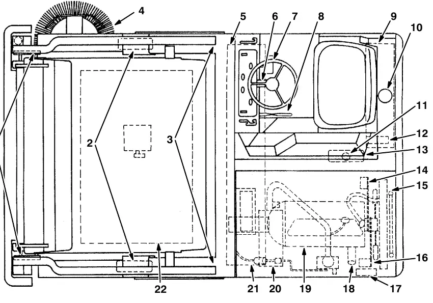
| Interval | Key | Description | Procedure | Lubricant | No. of service points |
|---|---|---|---|---|---|
| Daily | 20 | Engine air filter | Check restriction indicator | – | 1 |
| Empty dust cap | – | 1 | |||
| 19 | Engine crankcase | Check oil level | EO | 1 | |
| 15 | Radiator core exterior | Check for debris and clean | – | 1 | |
| 5 | Floor skirts | Check for damage, wear and adjustment | – | 5 | |
| 5 | Main brush | Check for damage, wear, and adjustment | – | 1 | |
| 4 | Side brush | Check for damage, wear, and adjustment | – | 1 | |
| 21 | Fuel water trap-filter, diesel | Drain water | – | 1 | |
| – – | Scrub attachment | Check squeegee for damage, wear, and adjustment | – | 1 | |
| Check scrub brush for damage, wear, and adjustment | – | 1 | |||
| 50 Hours | 18 | Engine crankcase | Change oil and filter element Parts › | EO | 1 |
| 5 | Main brush | Rotate end-for-end | – | 1 | |
| 100 Hours | 22 | Hopper dust filter | Inspect, clean or replace Parts › | – | 1 |
| 15 | Radiator | Check coolant level | WG | 1 | |
| 9 | Hydraulic fluid reservoir | Check fluid level | HYDO | 1 | |
| 13 | Rear tire | Check pressure | – | 1 | |
| 5 | Dust seals | Check for damage or wear | – | 8 |
Maintenance chart (continued)
| Interval | Key | Description | Procedure | Lubricant | No. of service points |
|---|---|---|---|---|---|
| 200 Hours | 14 | Alternator and fan belt | Check tension | – | 1 |
| 16 | Governor belt (For machines below serial number 010750) | Check tension | – | 1 | |
| 1 | Hopper door latches, multi-level dump model | Lubricate | MPGM | 2 | |
| 8 | Parking brake | Check adjustment | – | 1 | |
| 7 | Brake pedal | Check and adjust travel | – | 1 | |
| 11 | Rear wheel support bearing | Lubricate | MPGP | 1 | |
| 3 | Hopper lift arm pivots | Lubricate | MPGM | 2 | |
| – – | Scrub attachment | Lubricate casters | MPGM | 4 | |
| Lubricate hopper pivots | MPGM | 2 | |||
| 400 Hours | 19 | Engine, gasoline, LPG (For machines below serial number 010750) | Check and adjust valve clearance | – | 8 |
| Check and adjust idle speed | – | 1 | |||
| Check and adjust carburetor idle mixture | – | 1 | |||
| Clean or replace and adjust spark plugs Parts › | – | 4 | |||
| Check distributor and adjust timing | – | 1 | |||
| Replace PCV valve. Clean PCV hoses, tubes, and fittings Parts › | – | – | |||
| 19 | Engine, gasoline, LPG (For machines serial number 010750 and above) | Check and adjust valve clearance | – | 8 | |
| Check and adjust idle speed | – | 1 | |||
| Check and adjust carburetor idle mixture | – | 1 | |||
| Clean or replace and adjust spark plugs Parts › | – | 4 | |||
| Replace PCV valve. Clean PCV hoses, tubes, and fittings Parts › | – | – | |||
| 2 | Front wheel bearings | Inspect and lubricate | MPGP | 2 | |
| 9 | Hydraulic fluid reservoir | Change hydraulic fluid Parts › | HYDO | 1 | |
| 17 | Hydraulic fluid filter | Change filter element Parts › | – | 1 | |
| 6 | Steering gear case | Check grease level | MPG | 1 | |
| 21 | Fuel filter, diesel | Replace element Parts › | – | 1 | |
| 800 Hours | 19 | Engine, gasoline, LPG | Torque intake manifold bolts | – | 4 |
| 15 | Cooling system | Flush | WG | 1 | |
| 10 | Hydraulic reservoir | Replace breather cap Parts › | – | 1 | |
| 12 | Hydraulic reservoir | Replace suction strainer Parts › | – | 1 |
Lubricant codes
| Code | Lubricant |
|---|---|
| EO | Engine oil |
| HYDO | Tennant Company or approved hydraulic fluid |
| MPG | Multi-purpose, calcium soap base grease |
| MPGM | Multi-purpose, water resistant, lithium base, moly-disulphide EP grease |
| MPGP | Multi-purpose grease, paraffin base with organic thickener. |
| WG | Water and permanent-type ethylene glycol anti-freeze, one-to-one ratio |
NOTE: More frequent intervals may be required in extremely dusty conditions.
Lubrication
Engine
Check the engine oil level daily. Change the engine oil and oil filter after every 50 hours of operation.
Gasoline and LPG engines
Gasoline and LPG powered engines should be lubricated with SAE–SE/SF rated engine oil.
The following SAE–SE/SF rated oil grades are recommended for engines during changing seasonal temperatures:
| Multi-viscosity oils: ambient temperature | Oil grade |
|---|---|
| Below 32°F (Below 0°C) | 5W 30 |
| –10° to 90°F (–23° to 32°C) | 10W 30 |
| –10° to 90°F (–23° to 32°C) | 10W 40 |
| Above 10°F (Above –12°C) | 20W 40 |
| Single viscosity oils: ambient temperature | Oil grade |
|---|---|
| –10° to 32°F (–23° to 0°C) | 10W |
| 10° to 60°F (–12° to 16°C) | 20W 20 |
| 32° to 90°F (0° to 32°C) | 30 |
| Above 60°F (Above 16°C) | 40 |
The engine oil capacity is 3.5 qt (3.3 L) including the oil filter.
Diesel engines
Diesel powered engines should be lubricated with SAE–CC/CD rated engine oil.
The following oil grades are recommended for engines operating in the ambient temperatures listed.
| Single and multi-viscosity oils: ambient temperature | Oil grade |
|---|---|
| Below 32°F (Below 0°C) | 10W, 10W 30 |
| 32° to 77°F (0° to 25°C) | 20 |
| Above 77°F (Above 25°C) | 30 |
The engine oil capacity is 7 qt (6.7 L) including the oil filter.
Steering gear
The steering gear controls the steering arm. A square head plug has been provided on the left side of the steering gear to check the grease level and to allow filling.
Check the steering grease level after every 400 hours of operation. Fill the unit with a calcium base soap grease.
Rear wheel support
The rear wheel support pivots the rear wheel. A grease fitting has been provided on the support bracket for lubrication purposes. Lubricate the rear wheel support bearing with a grease gun after every 200 hours of operation. Use a multi-purpose, water resistant, paraffin base grease with organic thickener.
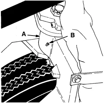
Front wheel bearings
The front wheel bearings support the front half of the machine. Inspect the bearings for contamination, seal damage, and repack after every 400 hours of operation. Use a multi-purpose, water resistant, paraffin base grease with organic thickener.
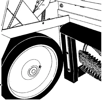
Hopper lift arm pivots
The hopper lift bearings support the lift arm pivots. Two grease fittings are used to lubricate the hopper lift bearings. One grease fitting is located on each of the hopper lift bearings.
Access to the left side grease fitting is through the left side access door. The right side grease fitting is exposed to the operator compartment through an access hole in the front dash panel.
Lubricate the bearings with a grease gun after every 200 hours of operation. Use a multi-purpose, water resistant, lithium base, moly-disulphide EP grease, or a paraffin base grease with organic thickener.
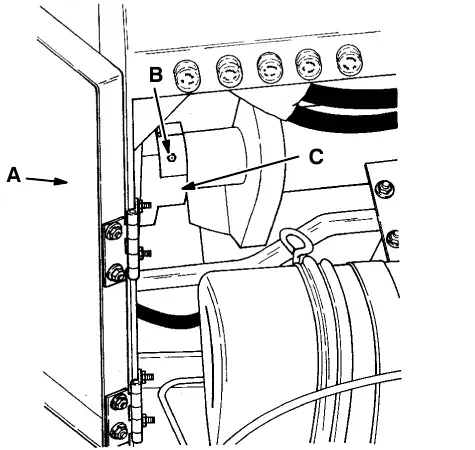
A. Left Side Access Door
B. Grease Fitting
C. Lift Bearing
Hopper door latches
The hopper door latches latch the hopper door on multi-level dump model machines. Two grease fittings are used to lubricate the hopper door latches. One grease fitting is on each of the latches.
To gain access to the latch grease fittings, place the hopper in the “dump” position.
Lubricate the latches with a grease gun after every 200 hours of operation. Use a multi-purpose, water resistant, lithium base, moly-disulphide EP grease, or a paraffin base grease with organic thickener.
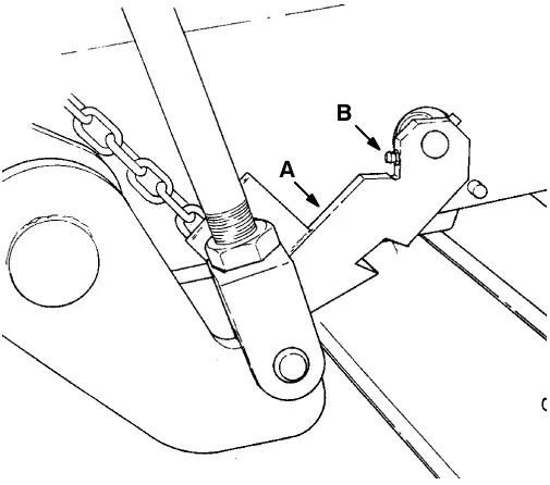
A. Hopper Door Latch
B. Grease Fitting
Scrub attachment leg casters
The scrub attachment casters support the scrub attachment when it is not mounted to the machine. A grease fitting is mounted to the axle of each of the four casters. Lubricate the casters with a grease gun after every 200 hours of operation. Use a multi-purpose, water resistant, lithium base, moly-disulphide EP grease, or a paraffin base grease with organic thickener.
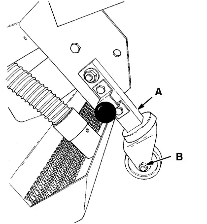
A. Leg
B. Grease Fitting
Scrub attachment debris hopper
The scrub attachment debris hopper collects debris picked up by the scrub brushes. The debris hopper pivots on two bearings. Each bearing is equipped with a grease fitting. Lubricate the bearings with a grease gun after every 200 hours of operation. Use a multi-purpose, water resistant, lithium base, moly-disulphide EP grease, or a paraffin base grease with organic thickener.
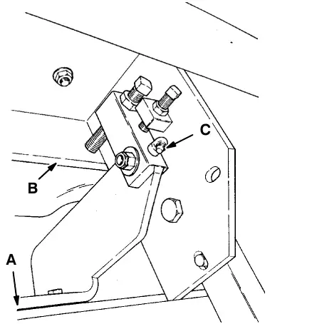
A. Hopper
B. Scrub Attachment Frame
C. Grease Fitting
Hydraulics
Hydraulic fluid
Hydraulic fluid drives most of the moving components of the machine. The quality and condition of the hydraulic fluid play a very important role in how well the machine operates. Tennant Company has developed its own hydraulic fluid to meet the special needs of its machines.
TENNANT® Hydraulic Fluid is a specially compounded oil with the following features not found in many hydraulic fluids:
- Flat viscosity curve.
- Additives to prevent corrosion.
- Additives to prevent oxidation.
- Rust inhibitors.
- Foam suppressors.
These features restrict foaming of the hydraulic fluid and provide a high standard of lubrication to the components.
| Viscosity (SUS) | TENNANT® Hyd. Fluid No. 32397 (HP1040) | TENNANT® Hyd. Fluid No. 32398 (HP2060) |
|---|---|---|
| SUS @ 100° F (38° C) | 404–445 | 940–1010 |
| SUS @ 210° F (99° C) | 78–84 | 122–130 |
TENNANT® Hydraulic Fluids have a very flat viscosity curve (synonymous with “high viscosity index”). The flat viscosity curve means that the thickness of the fluid is very constant over wide temperature ranges.
Hydraulic fluid with the viscosity rating of HP1040 should be used in machines that are operated in areas which have ambient temperatures up to 90° F (32° C). Use the HP2060 rated hydraulic fluid in areas which have ambient temperatures above 90° F (32° C).
Hydraulic fluid reservoir
Hydraulic fluid is stored in the hydraulic fluid reservoir. The reservoir holds 5 gal (19 L) of hydraulic fluid. The reservoir is located behind the operator seat.
A breather-filler cap and fluid level dipstick is mounted on top of the reservoir. The breather relieves excess pressure in the reservoir. The breather is mounted on top of the hydraulic fluid reservoir and seat support. The breather should be replaced after every 800 hours of operation.
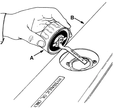
A. Breather-Filler Cap
B. Seat Support
The hydraulic fluid level dipstick is built into the breather-filler cap. The end of the dipstick is marked with “full” and “add” levels. This indicates the level of hydraulic fluid in the reservoir. The hopper must be lowered when checking reservoir fluid level.
Check the hydraulic fluid level after every 100 hours of operation. It should be above the “add” marks on the dipstick, but not above the “full” mark when the hydraulic fluid is warm.
Do not overfill the hydraulic fluid reservoir. Hydraulic fluid expands as it heats to its normal operating temperature. Always allow for expansion when filling the reservoir.
Drain and refill the hydraulic fluid reservoir with hydraulic fluid after every 400 hours of operation.
The hydraulic system is kept clean to a level of 10 microns by a hydraulic fluid filter. The hydraulic fluid filter is located under the radiator. Replace the filter element after every 400 hours of operation.
A reservoir outlet strainer is built into the reservoir to filter hydraulic fluid before it enters the system. Replace the strainer after every 800 hours of operation.
To drain hydraulic fluid reservoir and replace filter element
- Stop the engine and set the machine parking brake.
- Allow the hydraulic fluid to cool.
- Unthread and discard the hydraulic fluid filter element. Hydraulic fluid will drain through the filter head. Discard the used hydraulic fluid.
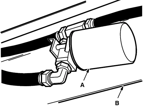
A. Filter Element
B. Machine Frame
NOTE: Be aware the hydraulic filter is lower than the reservoir. All fluid will drain from the reservoir. Discard all hydraulic fluid drained from the system. It may contain foreign material harmful to the hydraulic system.
- Apply a thin coat of hydraulic fluid to the seal of the new hydraulic fluid filter element.
- Thread and hand tighten the new hydraulic fluid filter element on the filter head.
- Operate the machine and check for leaks. Correct any leaks found.
- Check the hydraulic fluid reservoir level and fill as required.
To fill hydraulic fluid reservoir
- Remove the reservoir breather-filler cap.
- Pour new, approved hydraulic fluid through a 200 mesh screened funnel and into the reservoir filler neck.
- Check the hydraulic fluid level in the reservoir with the reservoir dipstick.
- Add hydraulic fluid until the level in the reservoir is between the “add” and the “full” range. Do not overfill.
NOTE: Do not overfill the hydraulic fluid reservoir. As hydraulic fluid heats to its normal operating temperature, it expands. Always allow for this expansion when filling the hydraulic fluid reservoir.
- Place the reservoir breather-filler cap securely on the reservoir filler neck.
- Start engine and operate all of the hydraulic components. Then recheck the hydraulic fluid level.
Hydraulic pumps
The machine propelling pump is a variable displacement hydraulic piston pump. It is driven by the engine via a chain coupling.
The machine accessories pump is a hydraulic gear pump. It is tandem mounted to the hydraulic piston pump.
After repairing or replacing a hydraulic pump, or when system contamination is likely, change the hydraulic fluid in the reservoir and the hydraulic fluid filter.
Directional pedal
The directional pedal controls the flow of hydraulic fluid to the hydraulic drive motor. The pedal has three positions—“forward,” “neutral,” and “reverse.” The “forward” and “reverse” positions send hydraulic fluid to the drive motor to propel the machine.
The “neutral” position is the position in which the propelling pump sends no hydraulic fluid to the propelling motor. The machine should not creep when the pedal “neutral” position is correctly adjusted. Adjust the pedal linkages, as described in TO ADJUST DIRECTIONAL PEDAL, whenever the machine creeps or after replacing the hydraulic propelling pump or pump linkages. The pedal linkages should also be adjusted whenever the reverse speed seems excessive or inadequate.
To adjust directional pedal
- Stop the engine and set the machine parking brake.
- Block the machine tires and jack up the rear of the machine at the designated location.
- Block up the machine with jack stands in the designated locations. Make sure the rear tire clears the floor by 2 in (50 mm) and all obstacles within a 24 in (610 mm) radius.
- Loosen the centering spring bracket adjustment bolt jam nuts.
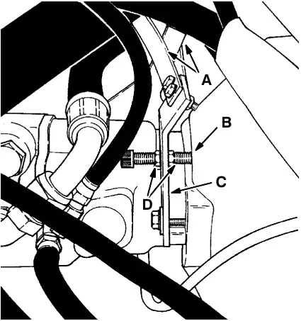
A. Centering Springs
B. Adjustment Bolt
C. Spring Bracket
D. Jam Nut
- Start the engine.
- Move the directional pedal into the “forward” position and release it. The rear wheel should stop rotating as soon as the pedal is released. Stop the engine and adjust the spring bracket as required.
- Move the directional pedal into the “reverse” position and release it. The rear wheel should stop rotating as soon as the pedal is released. Stop the engine and adjust the spring bracket as required.
- Tighten the jam nuts.
- Adjust the directional pedal linkage so it will contact the lintel when the directional pedal is pressed backward. The backward travel of the pedal should be restricted so the machine will not travel faster than 3.5 mph (5.6 km/h) with the throttle lever in the (Fast 1) position, and 4.5 mph (7.2 km/h) with the throttle lever in the (Fast 2) position in reverse. Adjust the pedal linkage connected to the pedal for pedal position. Adjust the pump linkage next to the engine for reverse speed control.
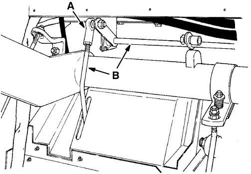
A. Ball Joint
B. Pedal Linkage
- Tighten the linkage ball joints and jam nuts.
- Raise the rear of the machine, remove the jack stands, and lower the machine.
Lift arm speed limiter
The lift arm speed limiter is present on multi-level dump model machines. It limits the forward speed the machine can travel when the hopper is raised. The speed limiter should be adjusted whenever the pump linkage is adjusted. The machine should not travel more than 2 mph (3.2 km/h) with the hopper raised.
The speed limiter consists of a roller bearing which is mounted on the directional linkage, and a cam on the lift arm. When the hopper is raised, the lift arm turns placing the cam under the roller bearing. This limits how far the directional pedal can be pressed, limiting the machine speed.
To adjust the maximum limited speed, loosen the roller bearing nut, reposition the roller bearing in its mounting slot and tighten the nut.
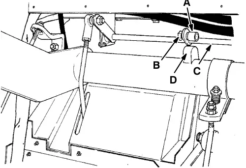
A. Speed Limiter Bearing
B. Retaining Nut
C. Pump Linkage
D. Lift Arm Cam
Hydraulic fluid leaks
Fluid escaping at high pressure from a very small hole can be almost invisible and can cause serious injuries. Use a piece of cardboard or wood, rather than hands, to search for suspected leaks.
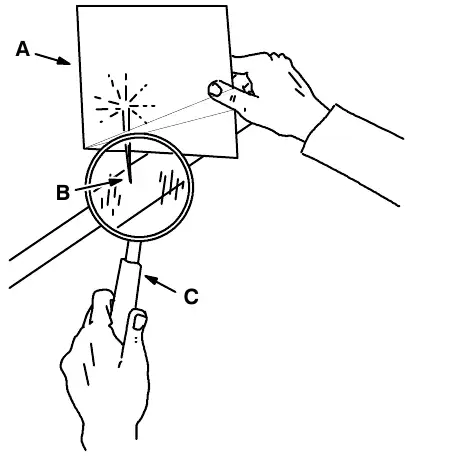
A. Cardboard
B. Pinhole Leak
C. Magnifying Glass
If injured by escaping hydraulic fluid, see a doctor at once. Serious infection or reaction can develop if proper medical treatment is not administered immediately.
Hydraulic schematic, low dump model
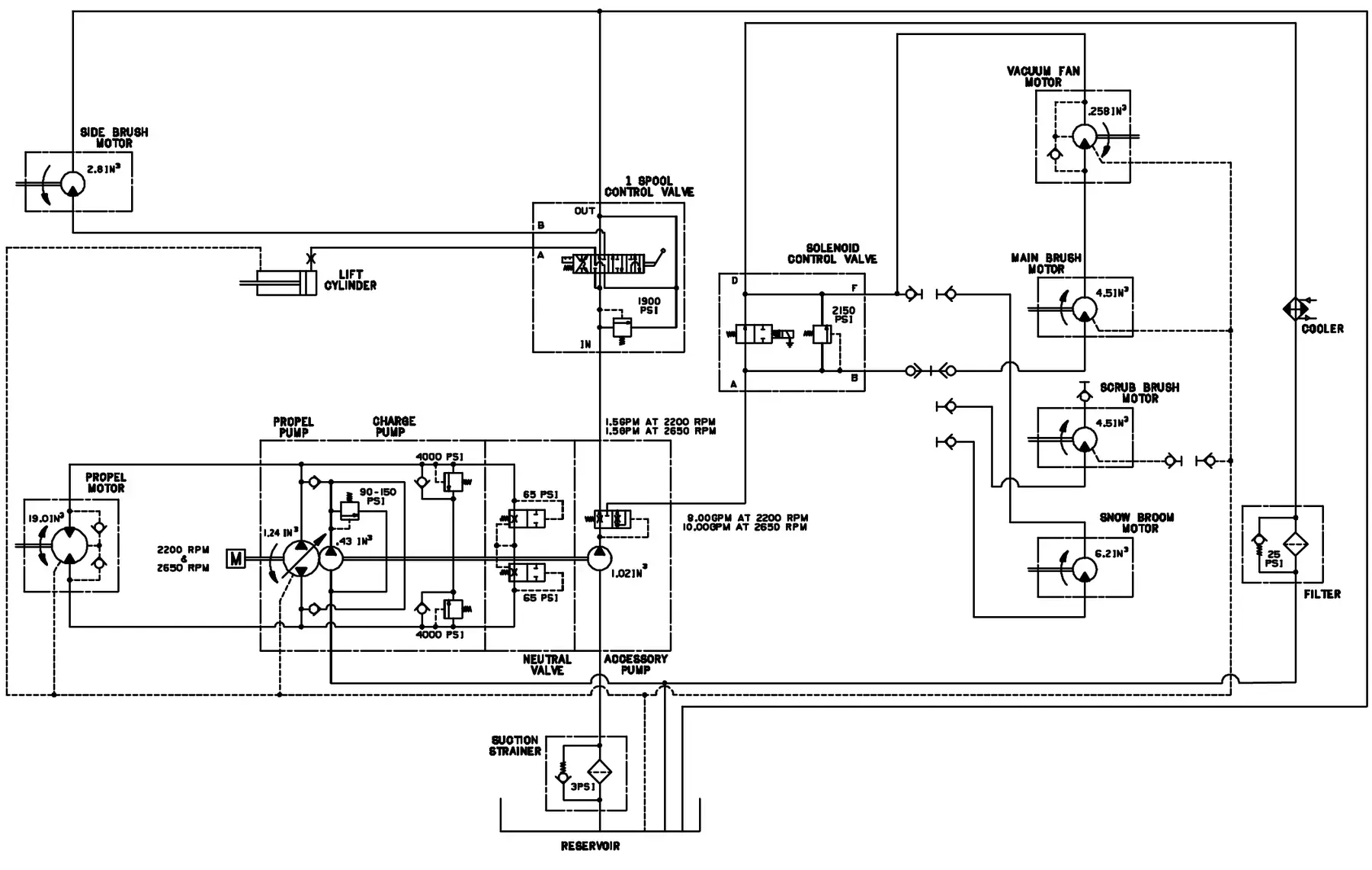
Hydraulic schematic, multi-level dump model
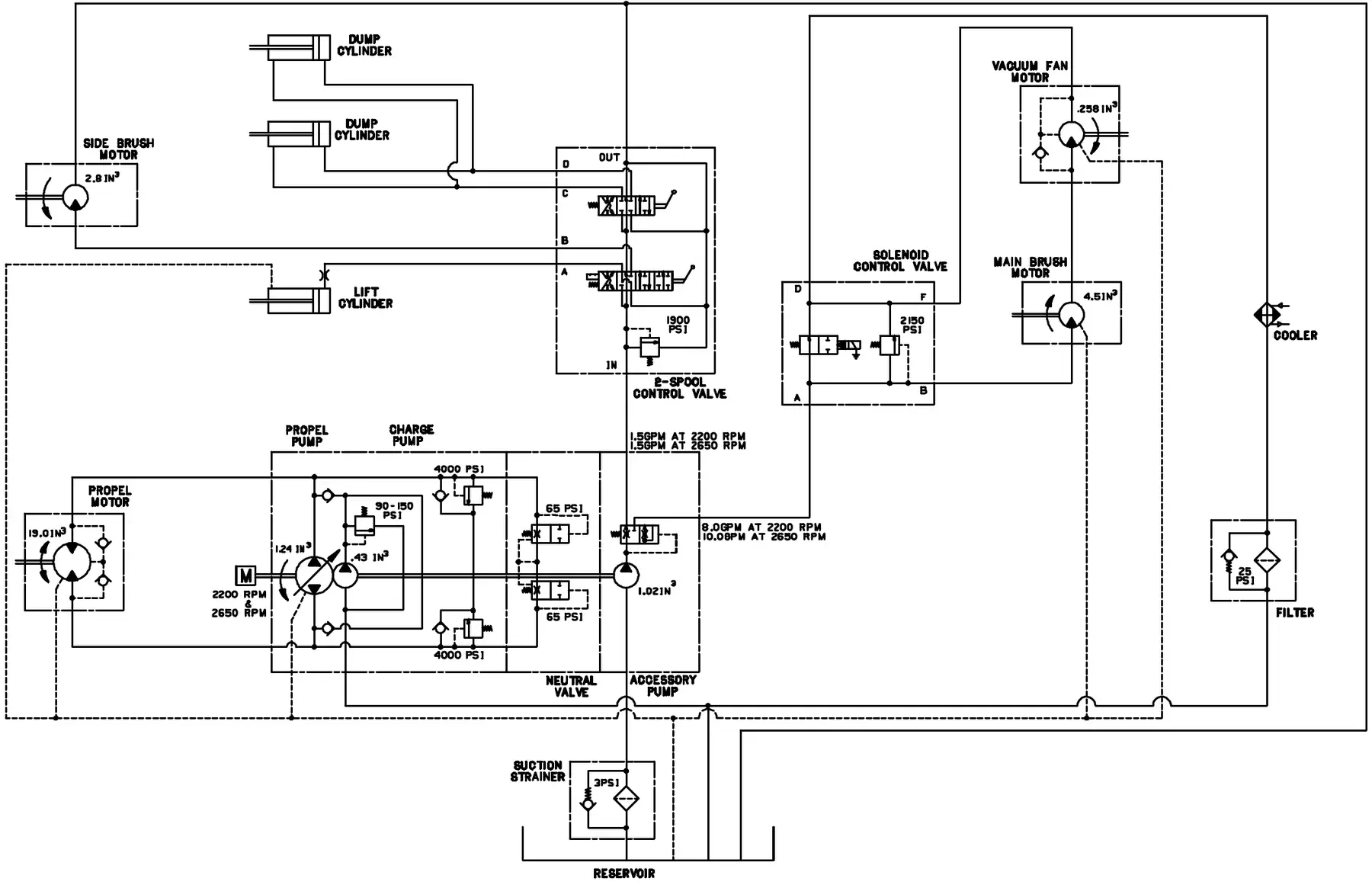
Hydraulic system troubleshooting
| Problem | Cause | Remedy |
|---|---|---|
| Machine travels slowly or not at all | Parking brake engaged | Release parking brake |
| Linkage broken or not adjusted properly | Replace and/or adjust linkage | |
| Relief valve stuck open – (leaking) | Replace relief valve one forward, one reverse | |
| Motor failure | See Hydraulic components troubleshooting: Hydraulic motor failure | |
| Pump failure | See Hydraulic components troubleshooting: Hydraulic piston pump failure | |
| Hydraulic fluid level low | Fill hydraulic fluid reservoir | |
| Main brush does not turn | Circuit breaker CB-3 tripped | Reset circuit breaker |
| Electric on-off switch S-4 failure | Replace switch | |
| Hydraulic valve failure | See Hydraulic components troubleshooting: Solenoid valve failure | |
| Hydraulic motor failure | See Hydraulic components troubleshooting: Hydraulic motor failure | |
| Gear pump failure | See Hydraulic components troubleshooting: Hydraulic gear pump | |
| Electric lift arm switch S-9 failure | Adjust or replace switch | |
| Thermo Sentry™ tripped | Reset or replace Thermo Sentry™ | |
| Relief valve stuck open – (leaking) | Replace relief valve | |
| Side brush turns slowly or not at all | Hydraulic valve failure | See Hydraulic components troubleshooting: Hydraulic control valve failure |
| Hydraulic motor failure | See Hydraulic components troubleshooting: Hydraulic motor failure | |
| Relief valve in valve sticking | Clean or replace relief valve | |
| Gear pump failure | See Hydraulic components troubleshooting: Hydraulic gear pump |
Parts ›
Hydraulic system troubleshooting (continued)
| Problem | Cause | Remedy |
|---|---|---|
| Poor or no vacuum to brush compartment | Circuit breaker CB-3 tripped | Reset circuit breaker |
| Electric on-off switch S-4 failure | Replace switch | |
| Hydraulic valve failure | See Hydraulic components troubleshooting: Hydraulic control valve failure | |
| Hydraulic motor failure | See Hydraulic components troubleshooting: Hydraulic motor failure | |
| Gear pump failure | See Hydraulic components troubleshooting: Hydraulic gear pump | |
| Electric lift arm switch S-9 failure | Adjust or replace switch | |
| Thermo Sentry™ tripped | Reset or replace Thermo Sentry™ | |
| Relief valve stuck open – (leaking) | Replace relief valve | |
| Hopper will not lift | Hydraulic valve failure | See Hydraulic components troubleshooting: Hydraulic control valve failure |
| Hydraulic orifice at lift cylinder plugged | Replace orifice | |
| Lift cylinder failure | See Hydraulic components troubleshooting: Hydraulic cylinder failure | |
| Hopper overloaded | Empty hopper | |
| Lift arms binding | Replace and/or adjust lift arm linkage | |
| Gear pump failure | See Hydraulic components troubleshooting: Hydraulic gear pump | |
| Hopper will not lower | Lift cylinder failure | See Hydraulic components troubleshooting: Hydraulic cylinder failure |
| Lift arms binding | Replace and/or adjust lift arm linkage | |
| Hopper will not roll out | Hydraulic valve failure | See Hydraulic components troubleshooting: Hydraulic control valve failure |
| Dump cylinder failure | See Hydraulic components troubleshooting: Hydraulic cylinder failure | |
| Gear pump failure | See Hydraulic components troubleshooting: Hydraulic gear pump | |
| Lift arms binding | Replace and/or adjust lift arm linkage |
Hydraulic components troubleshooting
| Problem | Cause | Remedy |
|---|---|---|
| Hydraulic cylinder failure | Piston seals leaking | Install seal kit |
| Barrel worn or rod bent | Replace cylinder | |
| Hydraulic control valve failure | Valve seals leaking | Install seal kit |
| Relief valve stuck open (leaking) | Clean or replace relief valve cartridge | |
| Solenoid valve failure | Valve leaking | Install seal kit |
| Solenoid failure | Replace solenoid coil | |
| Solenoid spool sticking | Replace valve cartridge | |
| Relief valve stuck open (leaking) | Clean or replace relief valve cartridge | |
| Hydraulic motor failure | Motor leaking | Install seal kit |
| Drive link failure | Replace drive link | |
| Gerotor worn | Replace gerotor set | |
| Output shaft failure | Replace output shaft and bearings | |
| Hydraulic gear pump failure | Pump leaking | Install seal kit |
| Gear set failure | Replace gear set | |
| Shaft failure | Replace gear set | |
| Flow divider failure | Replace back plate assembly | |
| Engine-to-pump coupling failure | Replace coupling | |
| Hydraulic piston pump failure | Pump leaking | Install seal kit |
| Relief valve stuck | Clean or replace relief valve | |
| Integral charge pump failure | Replace charge pump | |
| Rotating group worn | Replace rotating group | |
| Shaft failure | Replace shaft | |
| Backplate worn | Replace backplate | |
| Engine-to-pump coupling failure | Replace coupling |
Parts ›
Engine
Engine lubrication
Check the engine oil level daily. Change the engine oil and oil filter after every 50 hours of operation.
Gasoline and LPG engines
Gasoline and LPG powered engines should be lubricated with SAE-SE/SF rated engine oil.
The following SAE-SE/SF rated oil grades are recommended for engines during changing seasonal temperatures:
| Multi-viscosity oils | Below 32° F (Below 0° C) | –10° to 90° F (–23° to 32° C) | –10° to 90° F (–23° to 32° C) | Above 10° F (Above –12° C) |
|---|---|---|---|---|
| Oil grade | 5W 30 | 10W 30 | 10W 40 | 20W 40 |
| Single viscosity oils | –10° to 32° F (–23° to 0° C) | 10° to 60° F (–12° to 16° C) | 32° to 90° F (0° to 32° C) | Above 60° F (Above 16° C) |
|---|---|---|---|---|
| Oil grade | 10W | 20W 20 | 30 | 40 |
The engine oil capacity is 3.5 qt (3.3 L) including the oil filter.
Diesel engines
Diesel powered engines should be lubricated with SAE-CC/CD rated engine oil.
The following oil grades are recommended for engines operating in the ambient temperatures listed.
| Single and multi-viscosity oils | Below 32° F (Below 0° C) | 32° to 77° F (0° to 25° C) | Above 77° F (Above 25° C) |
|---|---|---|---|
| Oil grade | 10W | 20 | 30 |
| 10W 30 |
The engine oil capacity is 7 qt (6.7 L) including the oil filter.
Cooling system
Maintaining cooling system efficiency is important. Engine temperatures must be brought up to and maintained within the satisfactory range for efficient operation. However, the engine must be kept from overheating in order to prevent damage to the valves, pistons, and bearings. Check the radiator coolant level after every 100 hours of operation. Fill the cooling system through the coolant overflow tank — not through the radiator.
Use soft, clean water mixed with permanent-type, ethylene glycol antifreeze in a one-to-one ratio to fill the cooling system. Deposits of sludge, scale, and rust prevent normal heat transfer. Flush the radiator and the cooling system after every 800 hours of operation, with a cleaning compound.
Follow the mixing procedure recommended by the compound manufacturer. This is important because of the difference in concentration and composition of the cleaning compounds. After cleaning, flush the system with clean water.
Whenever a cooling system is badly rust-clogged, as indicated by overflow loss or abnormally high operating temperatures, corrective cleaning by reverse flow flushing will most effectively remove the heavy deposits of sludge, rust, and scale. The reverse flow flushing should be performed immediately after draining the cleaning solution. Flush the radiator first, then the engine, to allow the engine to cool as much as possible.
Engine overheating may also be caused by dirty radiator fins. The exterior fins of the radiator can be cleaned with an air or water hose. Check the radiator core exterior daily for debris.
Blow or rinse all dust, which may have collected on the radiator, in through the grill and radiator fins, opposite the direction of normal air flow. The grill and hydraulic cooler may be tilted back for easier cleaning. Use care not to bend the cooling fins when cleaning. Clean thoroughly to prevent caking dust. Clean the radiator and cooler only after the radiator has cooled to avoid cracking.
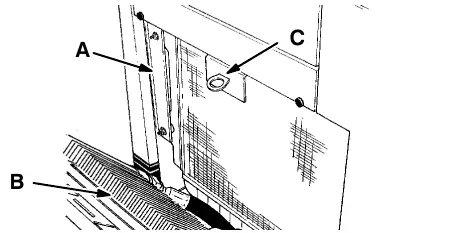
A. Radiator
B. Hydraulic Fluid Cooler
C. Retainer
The engine is equipped with a 180° F (82° C) thermostat. Normal engine temperature is 200° F (93° C). Temperatures up to 220° F (104° C) are allowable. Temperatures over 220° F (104° C) indicate a problem exists.
A pressure cap is used on the radiator to prevent overflow loss of water during normal operation. The spring-loaded valve in the cap closes the outlet to the overflow pipe of the radiator and thus seals the system. Pressure developing within the system raises the boiling point of the coolant and allows higher temperatures without overflow loss from boiling. The pressure valve opens at 7 psi (50 kPa), allowing steam and water to pass out the overflow pipe.
Air intake system
The importance of maintaining an air filter cannot be overemphasized. Dirt ingested through improperly installed, improperly serviced, or inadequate air filter elements wears out more engines than long hours of operation. Even a small amount of dirt will wear out a set of piston rings in just a few hours. Operating with a clogged air filter element also causes the fuel mixture to be richer, which can lead to formation of harmful sludge deposits in the engine. Always cover the air intake when the air filter is removed for servicing. Do not neglect servicing the air filter. Use only approved replacement parts. Keep all other air intake components secure and in good condition to prevent entrance of unfiltered air.
Overmaintenance can cause more damage than good. Removing the air filter element more often than is needed allows contaminants to enter the engine unnecessarily. Clean or replace the air filter element only when the restriction indicator indicates excessive restriction in the system.
Air filter restriction indicator
The air filter restriction indicator signals when to clean or replace the air filter element. Check the restriction indicator daily. The yellow indicator gradually becomes visible as the air filter element loads with dirt.
Do not clean or replace the air filter element until the yellow indicator reaches the top of the service indicator and reads 20 in (500 mm). The indicator may return to the “no restriction” position when the engine is shut off. It will return to the “visible” position when the engine is started.
Clean or replace the filter element when the yellow indicator reads 20 in (500 mm). After cleaning or replacing the air filter element, reset the service indicator by pushing the “reset” button on the end of the indicator.
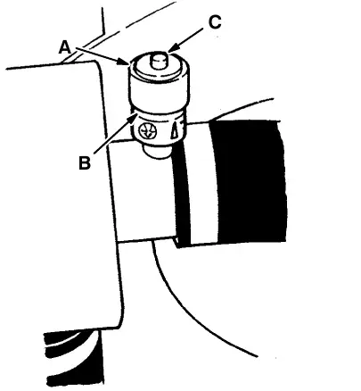
A. Restriction Indicator
B. Indicator Window
C. Indicator Reset Button
Air filter
The engine air filter housing includes a dust cap and two dry cartridge-type air filter elements.
The dust cap must be emptied of dirt daily.
The air filter element must be cleaned and inspected or replaced whenever the yellow indicator of the air filter restriction indicator reads 20 in (500 mm). The filter element must be replaced if it is damaged or has been cleaned three times.
Inside the air filter element is the air filter safety element. This element should be replaced, not cleaned after the regular element has been damaged or has been serviced three times.
Service the air filter element only when the restriction indicator indicates excessive restriction in the system. Do not remove the air filter element unless it is restricting air flow.
To replace air filter element
- Stop the engine and set the machine parking brake.
- Open the left side and top engine access doors.
- Unscrew the clamp ring on the filter.
- Remove the dust cap.
- Empty the dust cap.
- Remove the filter wing nut.
- Gently pull the filter element out of the filter housing.
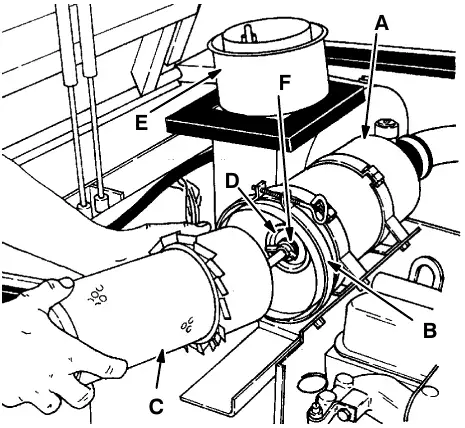
A. Filter Housing
B. Clamp Ring
C. Filter Element
D. Safety Air Filter Element
E. Dust Cap
F. Wing Nut
- Clean the interior of the air cleaner housing with a damp cloth. Clean the element sealing surfaces.
- Remove the safety element wing nut.
- Gently pull the safety element out of the filter housing.
- Clean and inspect the seals on the ends of the element. They should be unbroken and flexible. Remember, the safety element must be replaced after the regular element has been damaged or has been serviced three times.
- Install the safety element. Make sure the element is seating evenly. Tighten the wing nut.
- Using an air hose, direct dry, clean air maximum 30 psi (205 kPa) up and down pleats on the inside of the filter. Do not rap, tap, or pound dust out of the element.
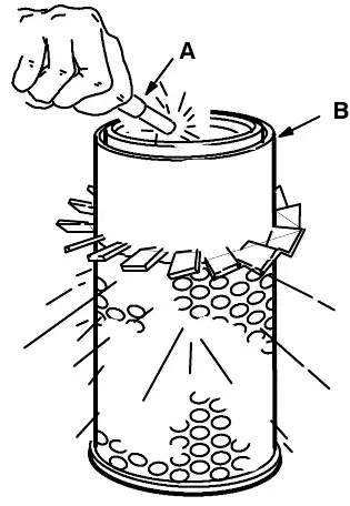
A. Air Hose
B. Filter Element
- After cleaning the air filter element, inspect it for damage by placing a bright light inside. The slightest rupture requires replacement of the filter. Clean and inspect the seals on the ends of the element. They should be unbroken and flexible. Remember, the element must be replaced after it has been cleaned three times.
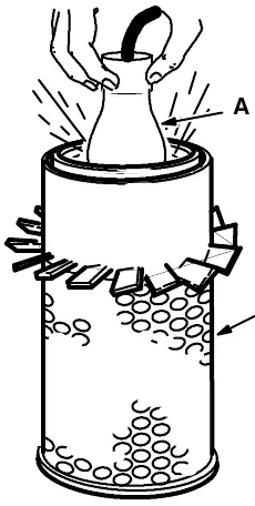
A. Bright Light
B. Filter Element
- Install the new or cleaned filter element so the fins on the element are at the intake end of the air cleaner. Use care so the fins are not damaged. Make sure the element is seating evenly. Tighten the element wing nut.
- Install the dust cap with the arrows pointing up. Tighten the clamp ring to hold it in place. Check all intake hose connections for leaks or abrasion.
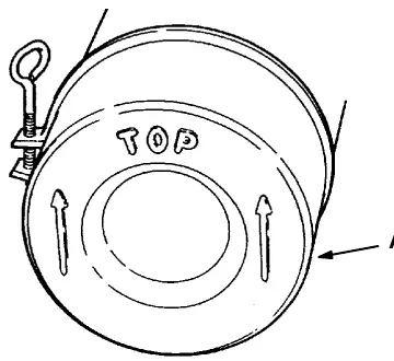
A. Dust Cap
- Reset the air filter restriction indicator.
- Close the access doors.
Fuel system – gasoline
Fuel filter
The fuel filter traps fuel impurities. It is located below the air filter. Replace the filter element as required.
Carburetor
The carburetor has two basic adjustments. Those adjustments are idle fuel mixture and idle speed. Check and adjust idle fuel mixture and idle speed after every 400 hours of operation. The idle fuel mixture is controlled by a screw located on the front of the carburetor. Turning the screw in, clockwise, leans the fuel mixture. Turning the screw counter-clockwise, richens the fuel mixture.
The idle speed is controlled by a screw located on the side of the carburetor next to the throttle linkage. Turning the screw clockwise increases engine speed. Turning the screw out, counterclockwise, decreases engine speed. Proper idle speed is 950 ± 50 rpm with all accessories in the “off” position.
Fuel system – LPG
LPG fuel system
The liquid withdrawal LPG fuel system is made up of five components which are: the LPG fuel tank, pressure relief valve, fuel filter lock, vaporizer-regulator, and the carburetor.
Liquid LPG fuel flows from the LPG tank, under its own pressure, to the pressure relief valve. This valve is normally closed, preventing LPG fuel from escaping into the atmosphere. The valve opens to relieve pressure if the fuel pressure exceeds system limits. From the pressure relief valve, the liquid LPG fuel is piped to the fuel filter lock.
The fuel filter lock filters unwanted tank scale and deposits out of the LPG fuel. The fuel filter lock also stops the flow of LPG fuel when the engine is not operating. The oil pressure switch controls the fuel filter lock. When the engine oil pressure is 5 psi (35 kPa) or greater, the oil pressure switch permits an electrical current to open the fuel filter lock which allows LPG fuel to flow on to the vaporizer-regulator. The oil pressure switch is bypassed when the engine is being started, allowing LPG fuel to flow.
The vaporizer section of the vaporizer-regulator converts the liquid LPG fuel into a gaseous LPG fuel. From the vaporizer section, the gaseous LPG fuel is sent to the primary regulator section of the vaporizer-regulator. The primary regulator section reduces the pressure of the LPG fuel. The secondary regulator section reduces the LPG fuel pressure to the level required by the carburetor. From the vaporizer-regulator, the LPG fuel is sent to the carburetor where it is finally metered into the air flow which is sent to the engine combustion chamber.
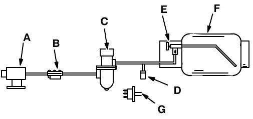
A. Carburetor
B. Vaporizer-Regulator
C. Fuel Filter Lock
D. Pressure Relief Valve
E. Tank Service Valve
F. LPG Fuel Tank
G. Oil Pressure Switch
Never operate an LPG powered machine if the LPG fuel system is leaking, or if any component in the fuel system is malfunctioning. Operating the machine under either of these conditions may cause a fire or explosion.
Check for frosting. Frosting does occur before the engine reaches operating temperature. Check after engine reaches operating temperature. If frosting occurs on or near any LPG component, there is a possibility of an LPG fuel leak or a malfunctioning component.
To locate the leak, apply a soapy water solution to the suspected area. Watch for bubbles forming in a confined area. This area may have an LPG fuel leak. Repair or replace the part. Use Loctite brand Stainless Steel PST thread sealant when reassembling. This epoxy-type sealant is not affected by aging or high humidity. Be sure to follow application directions and apply proper torque when reconnecting fittings.
Never bypass safety components except to test. If they are defective, replace them before operating the machine.
Check routings of all LPG hoses. Keep them away from sharp edges, exhaust manifolds, or other hot surfaces. Check for signs of abrasion or deterioration. Replace hoses found to be worn or damaged.
Fuel tanks
The LPG fuel tanks should be inspected for sharp dents, gouges, leaks, and broken protecting rings whenever the tanks are refilled. All tank valves must be inspected for leaks using a soap solution. Valves must also be checked for dirt, paint, or other debris in the valve openings. The following specific checks must also be made:
Filler Valve – Check for proper functioning and the presence of the handwheel. Valve must be closed except during filling.
Vapor and Liquid Service Valves – Check for proper functioning and presence of the handwheel. The valve must be closed except when in service.
Tank Service Valve Coupling – Check for proper functioning, thread condition, and damaged or missing washers or o-rings.
Safety Relief Valve – Check for damage. Check for the presence of the relief valve elbow and the proper direction of the elbow. If the rain cap is missing, check for foreign matter and replace cap. Do not tamper with the relief valve setting.
Liquid Level Gauge – Check operation against the maximum filling point as determined by weight.
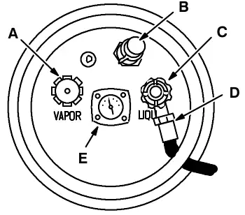
A. Filler Valve
B. Safety Relief Valve
C. Liquid Service Valve
D. Service Valve Coupling
E. Liquid Level Gauge
An LPG fuel tank with any of the stated defects must be removed from service and be repaired or destroyed accordingly.
If an LPG fuel tank is damaged or leaking, it should be removed to a designated safe area, and the proper personnel should be notified. Do not attempt to make repairs to the tank, regardless of condition. Repairs or disposal must only be made by qualified personnel.
The care an LPG fuel tank receives has a direct bearing on how long that tank can be used safely. LPG fuel tanks must not be dropped or dragged across any surface. To move LPG fuel tanks, use a hand truck or roll the tank on its foot ring while it is being held in a position slightly off vertical.
Whether the storage is inside or outside, fuel tanks should not be stored in the vicinity of combustible materials or high temperature sources such as ovens and furnaces, since the heat may raise the pressure of the fuel to a point where the safety relief valves would function. Care should be taken to insure that the tanks are stored in such a manner that if the safety relief valves do function, they will relieve vapor, rather than liquid.
Valves on empty tanks must be closed during storage and transportation.
Similar precautions should be taken in storing machines fitted with LPG fuel tanks. They may be stored or serviced inside buildings, provided there are no leaks in the fuel system and the tanks are not overfilled. While machines are being repaired inside a building, the shut-off valve on the tank must be closed, except when the engine must be operated.
The tank changing operation presents an opportunity for the machine operator to carefully observe the tank, fittings, and the fuel lines and fittings for his own satisfaction. If abnormal wear is detected, the operator should report it to the appropriate personnel for action.
To change an LPG fuel tank
- Park the machine in a designated safe area.
- Close the tank service valve.
- Operate the engine until it stops from lack of fuel, then set the machine parking brake.
- Put on gloves and remove the quick-disconnect tank coupling.
- Inspect the LPG fuel lines for wear or damage.
- Remove the empty LPG fuel tank from the machine.
- Check the tank for damage or wear.
- Store the tank in a designated safe area.
- Select a filled LPG fuel tank and inspect it for damage or leaks.
NOTE: Make sure the LPG fuel tank matches the fuel system (liquid tank with liquid system).
- Carefully place the LPG tank in the machine so that the tank centering pin enters the aligning hole in the tank collar.
NOTE: If the pin cannot be engaged, make sure you have the correct LPG fuel tank and then adjust the pin locator in or out.
- Fasten the tank hold-down clamp to lock the tank in position.
- Connect the LPG fuel line to the tank service coupling. Make sure the service coupling is clean and free of damage. Also make sure it matches the machine service coupling.
- Open the tank service valve slowly and check for leaks. If an LPG leak is found, close the service valve immediately and notify the appropriate personnel.
- If no leaks are found, the engine is ready to start.
Fuel filter lock
The fuel filter lock filters the LPG fuel. It also stops the flow of LPG fuel to the engine when the engine is not operating or when the engine oil pressure is less than 5 psi (35 kPa).
Replace the filter pack with the filter pack replacement kit if diminished gas flow indicates the filter is clogged. A drain plug is provided for purging the filter bowl. Clean out the bowl when replacing the filter pack.
Vaporizer-regulator
If any malfunction is noted, completely disassemble the vaporizer-regulator. Clean all of the parts in alcohol. Inspect all of the parts and replace where needed. Carefully reassemble the vaporizer-regulator with the seal repair kit. Check for proper operation.
Carburetor
If any malfunction is noted, completely disassemble the carburetor. Clean all of the parts in alcohol.
Inspect all of the parts and replace when needed. Carefully reassemble the carburetor with the seal repair kit.
Oil pressure switch
The engine oil pressure switch requires no regular maintenance. Never bypass the oil pressure switch as this is a safety feature which prevents LPG fuel from flowing when the engine is not operating properly.
LPG fuel troubleshooting
| Problem | Cause | Remedy |
|---|---|---|
| Engine will not start | Out of fuel | Replace fuel tank with full one |
| Service valve opened too quickly – engaging safety valve | Close valve and reopen slowly | |
| Plugged fuel filter | Replace filter | |
| Kinked or restricted fuel line | Straighten or replace fuel line | |
| Engine out of tune | Tune-up engine | |
| Oil pressure switch failure | Replace oil pressure switch | |
| Fuel lock valve failure | Repair or replace fuel filter lock | |
| Vaporizer-regulator failure | Repair or replace vaporizer-regulator | |
| Engine runs unevenly or lacks power | Wrong type of fuel tank – vapor withdrawal tank | Replace vapor withdrawal tank with liquid withdrawal tank |
| Plugged fuel filter | Replace filter | |
| Kinked or restricted fuel line | Straighten or replace fuel line | |
| Engine out of tune | Tune-up engine | |
| Restricted air filter | Clean or replace air filter element | |
| Vaporizer-regulator maladjusted | Adjust vaporizer-regulator |
Parts ›
Fuel system – diesel
Diesel fuel system
The diesel fuel system is made up of five basic components which are: fuel tank, fuel water trap-filter, fuel pump, injection pump, and injectors.
Fuel flows from the fuel tank through the fuel water trap-filter. The water trap-filter separates water and impurities from the fuel. From the fuel water trap-filter, fuel is drawn through the electric fuel pump and pumped to the injection pump. The injection pump pressurizes and sends fuel to the injectors. The injectors atomize and inject proper amounts of fuel into the combustion chamber at the proper times. Excess fuel is returned to the fuel tank through an overflow pipe.
Fuel water trap-filter
The fuel water trap-filter separates water and impurities from the fuel. It is located next to the engine bellhousing. The bottom portion of the unit is the water trap. The middle portion is the filter element.
Drain the water trap of water daily. To drain the water trap, loosen the drain knob on the bottom of the unit. First water, then diesel fuel will drain. Tighten the drain knob when diesel fuel appears.
Replace the fuel filter element and clean the water trap after every 400 hours of operation.
To replace fuel filter element
- Stop the engine and set the machine parking brake.
- Open the side and top engine access doors.
- Loosen the unit vent plug and open the water trap drain to drain diesel fuel.
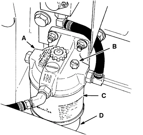
A. Filter Head
B. Vent Plug
C. Filter Element
D. Water Trap Bowl
- Remove the filter element and the water trap from the filter head.
- Remove the water trap bowl from the filter element.
- Clean the water trap bowl.
- Lubricate the o-ring and spin the water trap bowl onto the new filter element.
- Lubricate the o-ring and spin the filter element and water trap onto the filter head.
- Bleed the fuel lines of air as described in TO PRIME FUEL SYSTEM.
- Close the side and top engine access doors.
Priming fuel system
Priming the fuel system removes pockets of air in the fuel lines and fuel components. Air in the fuel system will prevent smooth engine operation.
Prime the fuel system after running out of fuel, changing fuel filter elements or repairing a fuel system component.
To prime fuel system
- Stop the engine and set the machine parking brake.
- Fill the fuel tank.
- Open the side and top engine access doors.
- Open the air vent on top of the fuel injection pump.
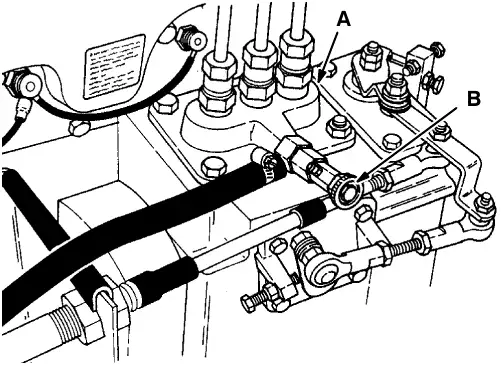
A. Injection Pump
B. Air Vent
- Start the engine, operate it for one minute, then stop it; or operate the starter motor in ten-second intervals until a steady stream of fuel flows from the vent.
- Close the air vent.
- Close the access doors.
Governor – gasoline, LPG (for machines below serial number 010750)
The governor controls engine speed. It is driven by a belt which spans the crankshaft sheave.
The governor is oil filled. It requires no regular inspections. Change the oil when performing major engine work. Use an SAE rated 10W30 or 10W40 engine oil.
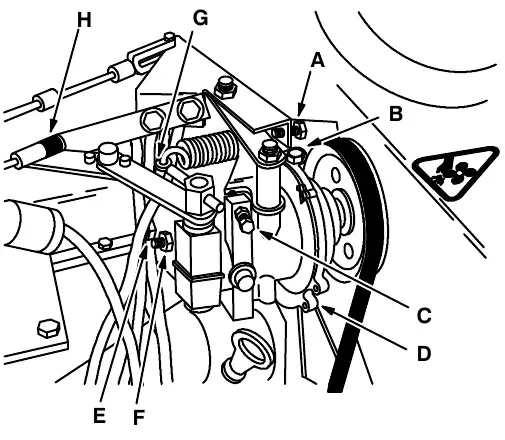
A. High Speed Stop Screw
B. Oil Fill Plug
C. Low Speed Stop Screw
D. Governor
E. Oil Level Plug
F. Surge Screw
G. Regulation Screw
H. Throttle Rod
The governor is factory set and should not be adjusted unless the engine speed varies from the specification or if the engine surges. The governor should be set so the engine operates at 2200 ± 50 rpm at “normal” speed setting under load and at 2650 ± 50 at “litter” speed setting under load. A surge screw has been provided to compensate for surging — adjust it with care or governor damage may result. The regulation screw has been factory set and should not be tampered with.
To adjust governor (for machines below serial number 010750)
- Operate the engine until it reaches normal operating temperature.
- Park on a level surface, stop the engine, and set the machine parking brake.
- Check the governor belt tension as described in GOVERNOR BELT.
- Place the throttle lever in the “normal” or (Fast 1) position. There should be a 0.03 to 0.06 in (1 to 2 mm) space between the carburetor lever and the lever stop. Adjust the throttle rod as required.
- Move the throttle lever to the (Idle) position. Start the engine and adjust the engine idle speed screw so the engine operates at 950 ± 50 rpm.
- Place the throttle lever in the “litter” or (Fast 2) position. Turn the side brush and main brushes on, and adjust the high speed stop screw so the engine operates at 2600 rpm. Then adjust the surge screw so the engine operates at 2650 rpm. Tighten all lock nuts.
- Place the throttle lever in the “normal” or (Fast 1) position. Adjust the low speed stop screw so the engine operates at 2200 ± 50 rpm.
- Stop the engine.
- Check and adjust the throttle cable position and the throttle lever stops to allow full linkage movement.
Governor – gasoline, LPG (for machines serial number 010750 and above)
The electronic governor controls engine speed. The governor consists of an ignition control assembly and control box located in front of the engine air cleaner, and an actuator mounted on the engine. The ignition control assembly and control box regulate the actuator, which in turn controls the throttle.
The electronic governor is factory set and is not user serviceable.
Ignition system – gasoline, LPG
Spark plugs
Clean or replace and adjust spark plugs after every 400 hours of operation. Spark plug gaps are best checked with a wire gauge unless the plug is dressed to obtain a correct reading with a flat gauge. The adjustment should always be made on the side electrode and never on the center electrode, which may cause a broken porcelain.
“Gapping” the electrode tip is more easily done with the proper tools.
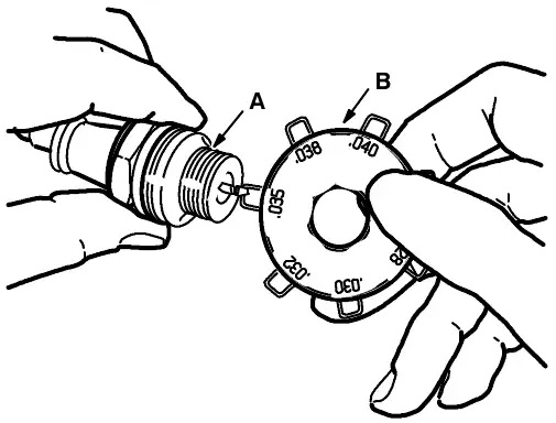
A. Spark Plug
B. Gapping Tool
The proper spark plug gap is 0.035 in (0.9 mm) for machines below serial number 010750. The proper spark plug gap is 0.039 in (1 mm) for machines serial number 010750 and above.
Spark plugs must be correctly installed in order to obtain good performance. It is a simple but important matter to follow these procedures when installing plugs:
- Clean the spark plug seat in the cylinder head.
- Use a new seat gasket and screw the plug in by hand.
- Tighten the spark plugs to 22 to 28 ft lb (30 to 38 Nm) with a socket wrench of the correct size.
Distributor (for machines below serial number 010750)
The distributor operation is vital to the operation of the engine. The following items should be carefully inspected after every 400 hours of normal operation; however, dirt, dust, water, and high speed operation may cause more rapid wear and necessitate more frequent inspections:
- Remove the distributor cap. Clean the cap and examine for cracks, carbon runners, or corroded terminals. If the vertical faces of the inserts are burned, install a new cap. If the horizontal faces of the inserts are burned, replace the cap and the rotor as this condition is caused by the rotor being too short. Inspect cap to distributor seal and the distributor housing breather.
- Check the centrifugal advance mechanism for “freeness” by turning the breaker cam in the direction of rotation and then releasing it. The advance springs should return the cam to its original position.
Engine ignition timing (for machines below serial number 010750)
The engine ignition timing must be checked with a timing light, using the timing points located on the front of the engine and the timing marks located on the crankshaft pulley. Distributor ignition timing should be checked after the first 50 hours of operation and after every 400 hours of operation thereafter.
To check and adjust the ignition timing with a scope, refer to the scope manufacturer’s instructions. To check and adjust the timing with a timing light, proceed as follows:
To check and adjust ignition timing (for machines below serial number 010750)
NOTE: Dwell angle must be correct or timing will not be accurate.
- Stop the engine and set the machine parking brake.
- Clean and mark the timing marks.
NOTE: Painting a white line on the front pulley timing marks will make them more visible under the timing light.
- Disconnect and plug the vacuum hose from the distributor.
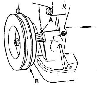
A. Timing Pointer
B. Crankshaft Pulley
- Connect the timing light to the No. 1 cylinder spark plug wire. Connect a tachometer to the engine.
- Start the engine and reduce the idle speed to 600 rpm to be sure that the centrifugal advance is not operating. Adjust the initial ignition timing to 6° BTDC on gasoline engines, and 10° BTDC on LPG engines.
To advance the timing, turn the distributor body clockwise. To retard the timing, turn the distributor body counterclockwise.
- Check the centrifugal advance for proper operation by starting the engine and accelerating it to approximately 2000 rpm. If the ignition timing advances, the centrifugal advance mechanism is functioning properly. Note the engine speed when the advance begins and the amount of total advance. Stop the engine.
- Unplug the vacuum line and connect it to the distributor vacuum advance unit. Start the engine and accelerate it to approximately 2000 rpm. Note the engine speed when the advance begins and the total amount of advance. Advance of the ignition timing should begin sooner and advance farther than when checking the centrifugal advance alone. Stop the engine.
- If the vacuum advance is not functioning properly, remove the distributor and check it on a distributor tester.
- After adjusting timing, be sure to increase the engine idle speed to its normal setting.
Engine ignition timing (for machines serial number 010750 and above)
The ignition system does not require any mechanical external adjustments, however the spark plug high tension leads must be inserted correctly, if ever removed, at each numbered coil position to the corresponding spark plug number in the cylinder (front to rear #1, 2, 3, and 4).
The ESC module controls the timing position in the start mode at 10° BTDC until the rpm reaches 250 rpm, thereafter the sensors are processed and timing is set to be compatible with engine speed, crankshaft position, engine load, engine coolant temperature and overspeed by the module.
Cylinder head – gasoline, LPG
Cylinder head
A three-stage torque procedure should be used when reassembling the cylinder head. The cylinder head bolts must be tightened after the first 50 hours of operation, for machines below serial number 010750 and seasonally thereafter for all gasoline and LPG machines.
Snug down cylinder head bolts in the proper sequence; first to 7 to 11 ft lb (10 to 15 Nm), then to 30 to 37 ft lb (40 to 50 Nm), then to 60 to 66 ft lb (80 to 90 Nm), and then after ten to fifteen minutes torque to 74 to 81 ft lb (100 to 110 Nm).
Tighten the intake manifold bolts to 15 to 18 ft lb (20 to 24 Nm) after every 800 hours of operation.
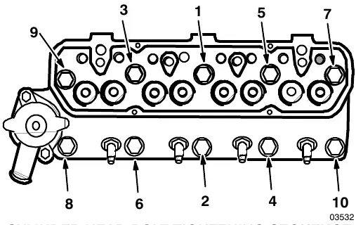
The cylinder head bolts must be retorqued after the engine is put into operation and brought up to proper operating temperatures. To retorque head bolts, follow the correct sequence. Loosen one head bolt at a time one-quarter turn, 90 degrees; then retorque it to the correct value.
NOTE: Power wrench torque limit must be held at least 10 ft lb (14 Nm) below hand torque specification; then hand torque to the specifications.
Valve tappet clearance
The valve tappet clearance must be checked and adjusted if necessary after every 400 hours of operation.
To set the valve clearance without the engine operating, rotate the crankshaft until No. 1 cylinder is at the top of the compression stroke. Check the timing marks. It should read 0 or TDC. Both valves on No. 1 cylinder are now closed. Set the valve clearance on both valves. Next, rotate the crankshaft 180°, and set the valve lash on both valves on No. 2 cylinder. Again rotate the crankshaft 180°, and set the valve lash on both valves on No. 4 cylinder. Rotate the crankshaft another 180°, and set the valve lash on both valves on No. 3 cylinder.
Check and adjust for machines below serial number 010750, the intake valve clearance from 0.009 in (0.22 mm), and the exhaust valve clearance from 0.023 in (0.59 mm) while the engine is cold.
Check and adjust for machines serial number 010750 and above, the intake valve clearance from 0.009 in (0.22 mm), and the exhaust valve clearance from 0.013 in (0.32 mm) while the engine is cold.
Cylinder head – diesel
Cylinder head
The cylinder head must be properly torqued after servicing to ensure proper operation. A three-stage torque procedure should be used. Snug down the cylinder head bolts and nuts in the proper sequence; first to one-third, then two-thirds, and then to the full torque specification of 55 to 60 ft lb (75 to 80 Nm). Retighten the bolts and nuts after operating the engine for 30 minutes.
NOTE: Power wrench torque limit must be held at least 10 ft lb (15 Nm) below torque specification. Hand tighten to specification.
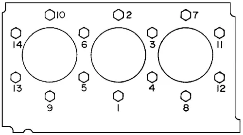
Valve clearance
The valve clearance must be properly adjusted after servicing or retorquing the cylinder head bolts to ensure proper operation. Measure valve clearance with a feeler gauge after aligning each cylinder on the compression top dead center stroke.
Adjust them with the engine cool to 0.0071 to 0.0087 in (0.18 to 0.22 mm) in the firing order 1–2–3.
Crankcase ventilation system
Clean the crankcase ventilation hoses, tubes, and fittings and replace the PCV valve after every 400 hours of operation.
Tune-up chart – gasoline, LPG
| Item | Specification |
|---|---|
| Idle speed, no load | 950 ± 50 rpm |
| (Fast 1) governed speed, under load | 2200 ± 50 rpm |
| (Fast 2) governed speed, under load | 2650 ± 50 rpm |
| Spark plug gap (for machines below serial number 010750) | 0.035 in (0.9 mm) |
| Spark plug gap (for machines serial number 010750 and above) | 0.039 in (1 mm) |
| Timing (for machines below serial number 010750) | 6° BTDC @ 600 rpm, gasoline 10° BTDC @ 600 rpm, LPG |
| Firing order | 1–2–4–3, counterclockwise rotation |
| Valve clearance, cold (for machines below serial number 010750) | 0.009 in (0.22 mm) intake 0.023 in (0.59 mm) exhaust |
| Valve clearance, cold (for machines serial number 010750 and above) | 0.009 in (0.22 mm) intake 0.013 in (0.32 mm) exhaust |
Electrical system
Battery
The battery used in the machine is a low maintenance battery. It has been constructed with special materials and has extra electrolyte to reduce or eliminate maintenance. Its design reduces electrolyte loss and contamination. Do not add water, remove the battery vent plugs, or check the battery specific gravity. For specific instructions, see the battery label.
The battery is rated at 12 V, 475 ccA. It is located under the operator foot plate. When removing battery cables, remove the negative (–) cable before the positive (+) cable.
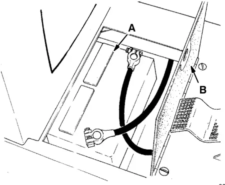
A. Battery
B. Floor Plate
Do not allow the battery to remain in discharged condition for any length of time. Do not operate the machine if the battery is in poor condition or discharged beyond 80%, specific gravity below 1.120.
Clean the top surface and the terminals of the battery periodically. Use a strong solution of baking soda and water. Brush the solution sparingly over the battery top, terminals, and cable clamps. Do not allow any baking soda solution to enter the battery. Use a wire brush to clean the terminal posts and the cable connectors. After cleaning, apply a coating of clear petroleum jelly to the terminals and the cable connectors. Keep the top of the battery clean and dry.
Keep all metallic objects off the top of the battery, as they may cause a short circuit. Replace worn or damaged wires.
The electrolyte level in regular nonsealed batteries can be checked. It must always be above the battery plates. Add distilled water to maintain solution at the correct level above the plates, but do not overfill. Never add acid to batteries, only water. Keep vent plugs firmly in place at all times, except when adding water or taking hydrometer readings.
If when checking battery specific gravity, one or more battery cells tests lower than the other battery cells, (0.050 or more) the cell is damaged, shorted, or is about to fail.
NOTE: Do not take readings immediately after adding water—if the water and acid are not thoroughly mixed, the readings may not be accurate. Check the hydrometer readings against this chart:
| Specific gravity at 80° F (27° C) | Battery condition |
|---|---|
| 1.260 – 1.280 | 100% charged |
| 1.230 – 1.250 | 75% charged |
| 1.200 – 1.220 | 50% charged |
| 1.170 – 1.190 | 25% charged |
| 1.110 – 1.160 | Discharged |
NOTE: If the readings are taken when the battery electrolyte is any temperature other than 80° F (27° C), the reading must be temperature corrected.
To determine the corrected specific gravity reading when the temperature of the battery electrolyte is other than 80° F (27° C):
Add to the specific gravity reading 0.004 (4 points) for each 10° F (6° C) above 80° F (27° C).
Subtract from the specific gravity reading 0.004 (4 points) for each 10° F (6° C) below 80° F (27° C).
Electrical schematic – gasoline, LPG (for machines below serial number 010750)
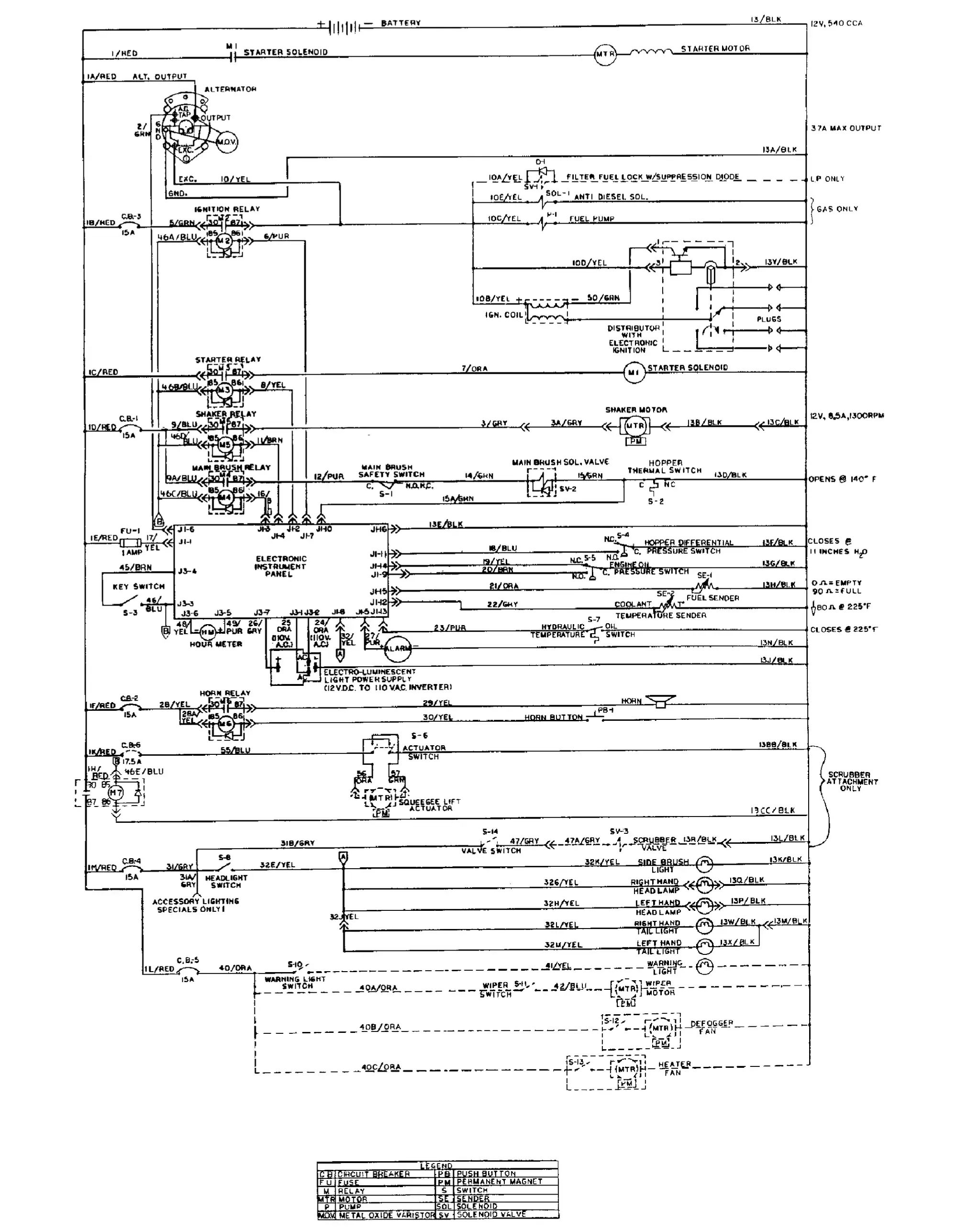
Electrical schematic – gasoline, LPG (for machines serial number 010750 and above)
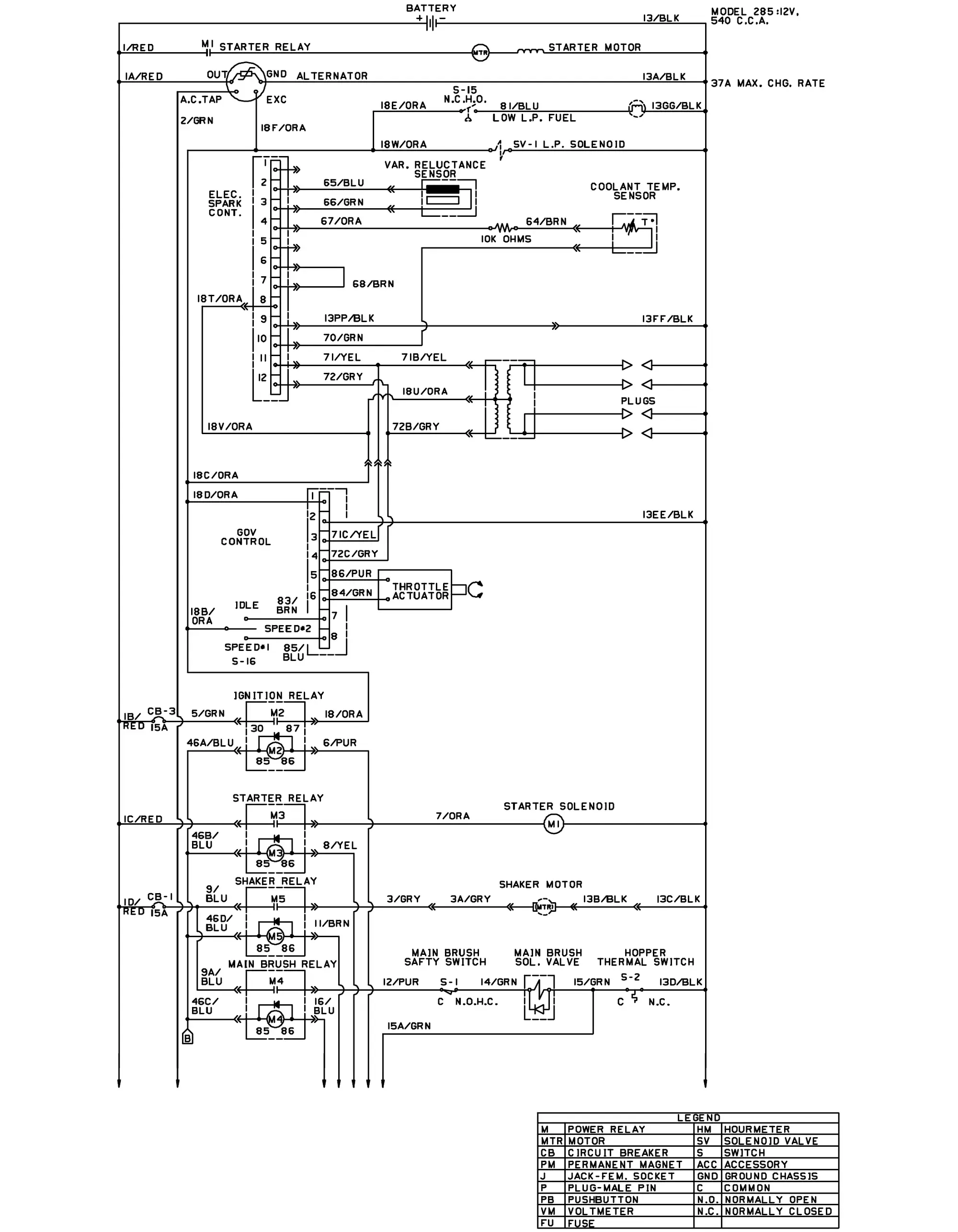
Electrical schematic – gasoline, LPG (for machines serial number 010750 and above)
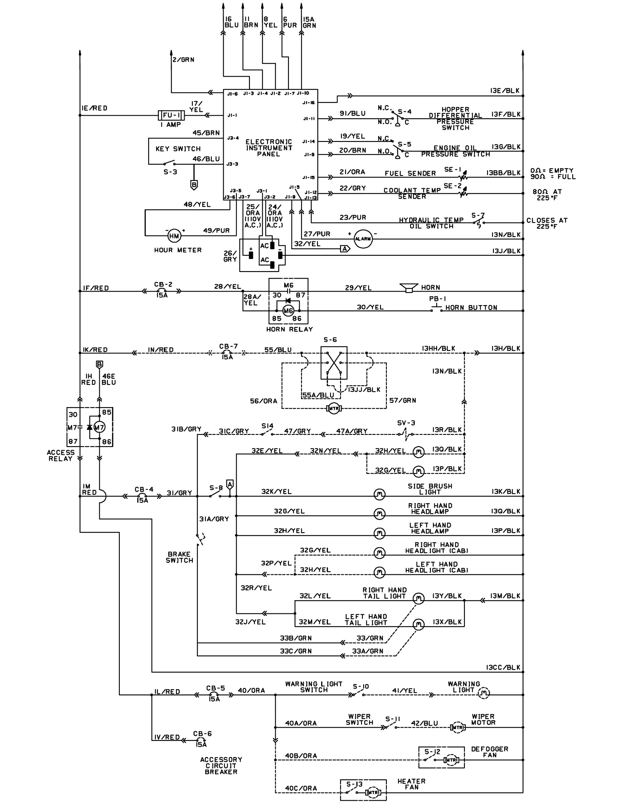
Electrical schematic – diesel (for machines below serial number 010750)
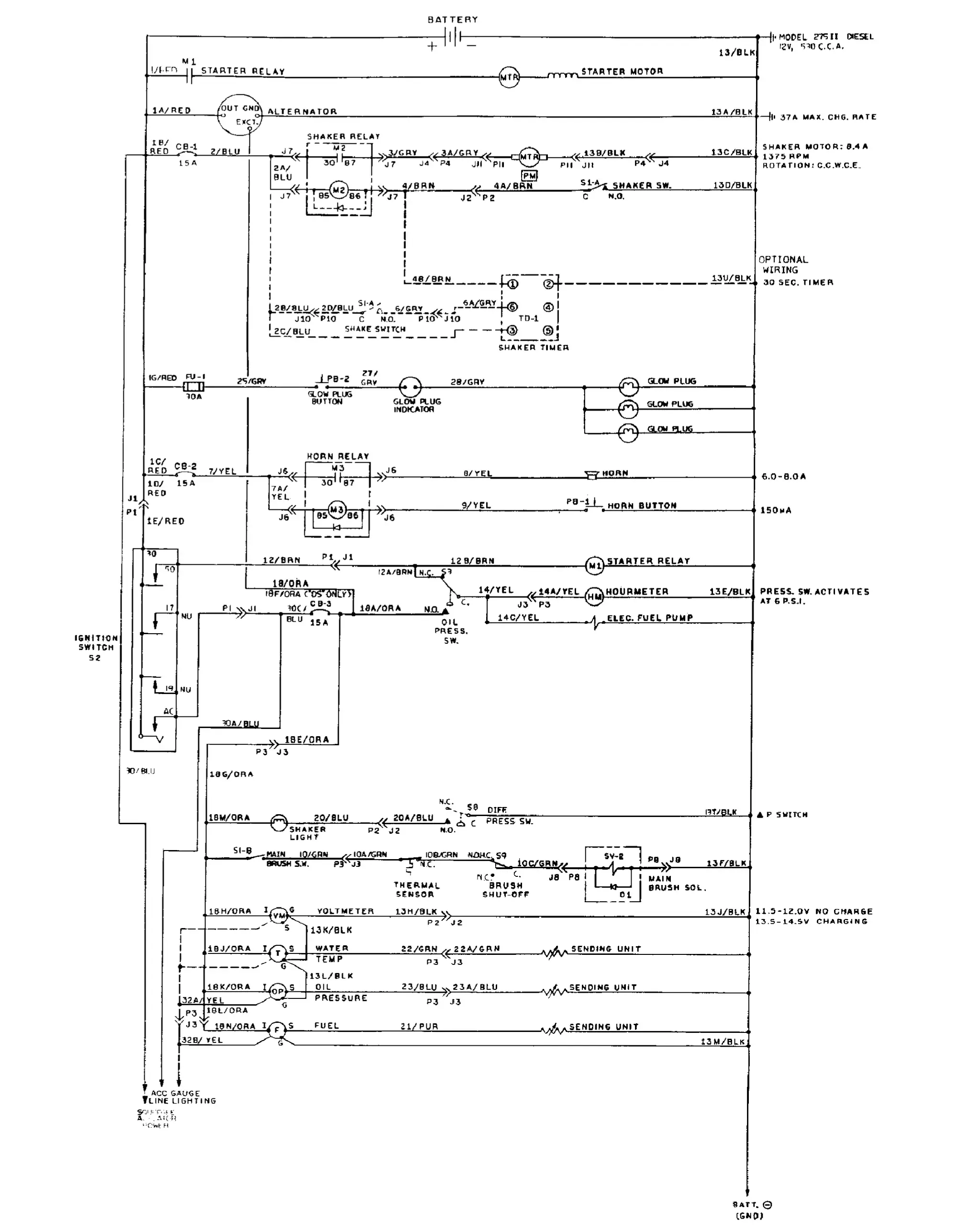
Electrical schematic – diesel (for machines serial number 010750 and above)
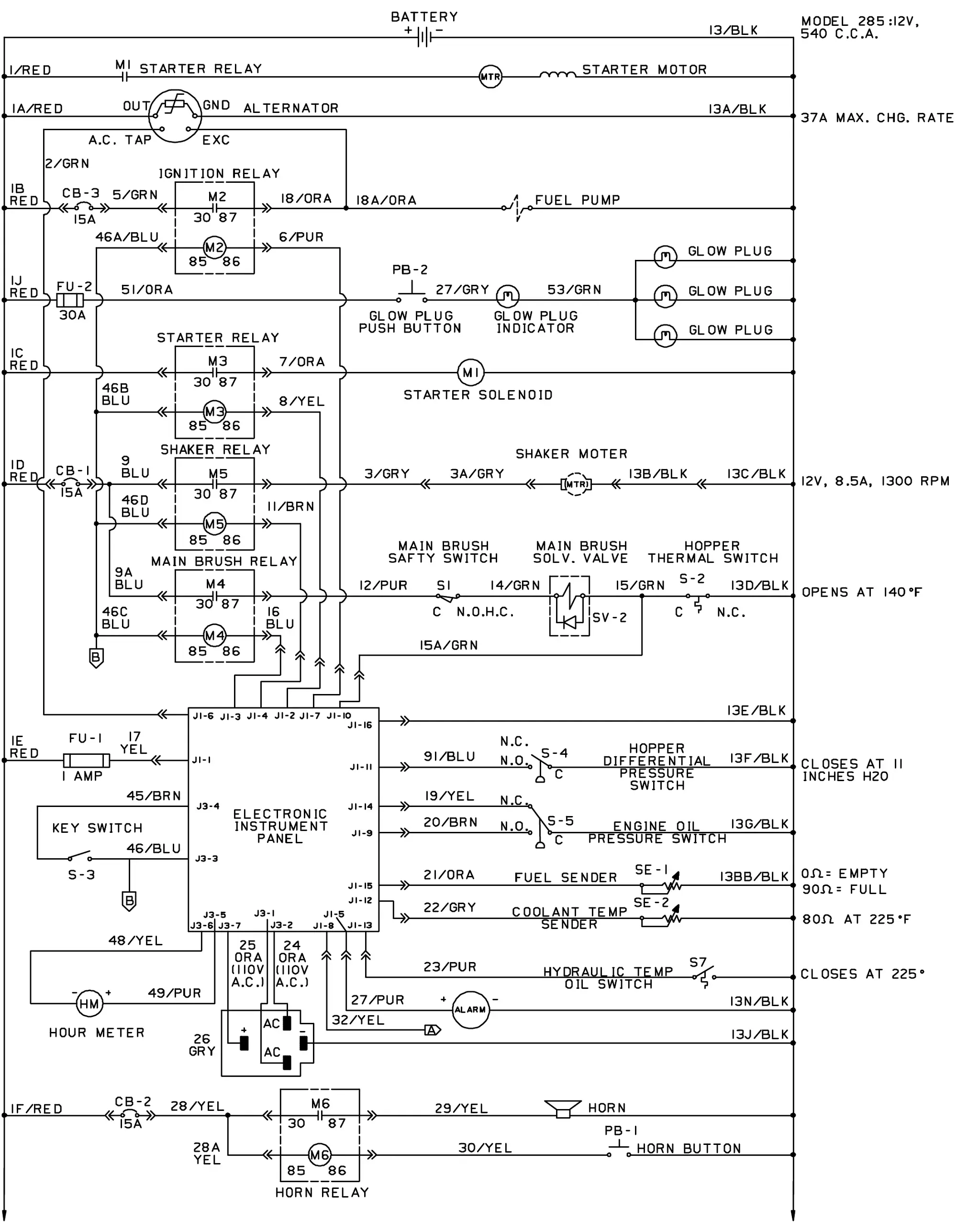
Electrical schematic – diesel (for machines serial number 010750 and above)
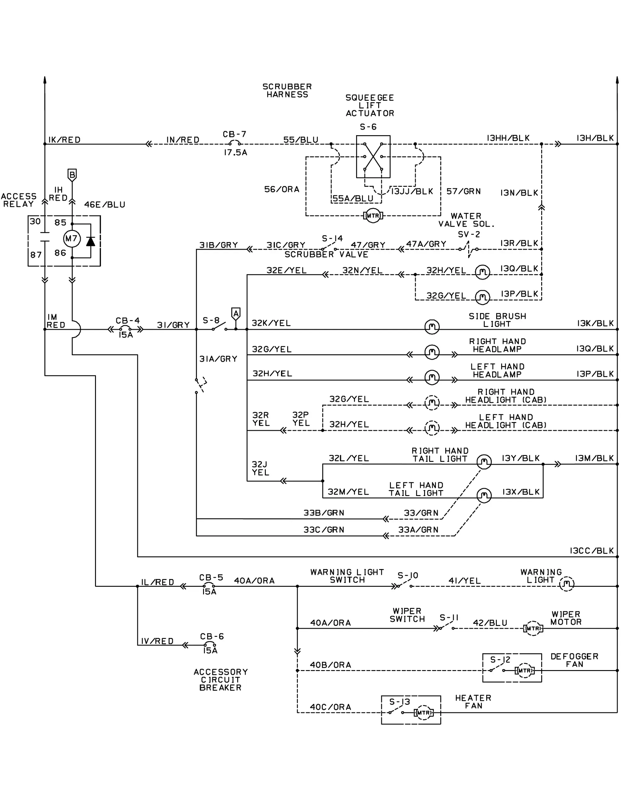
Electrical schematic – auto shaker, RFS
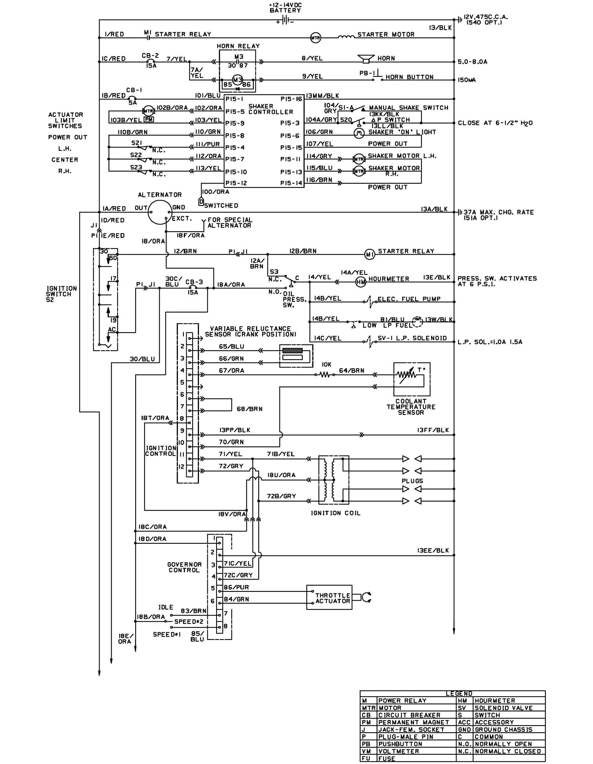
Electrical schematic – auto shaker, RFS
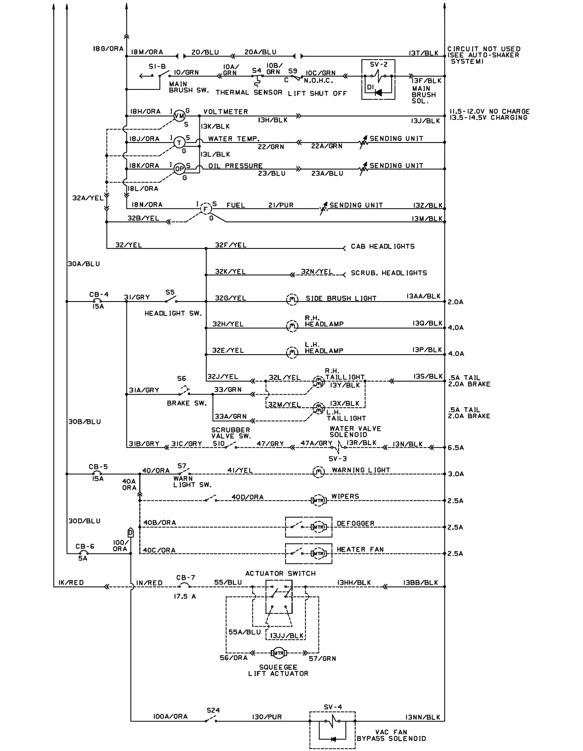
Belts and chains
Engine fan belt
The engine fan belt is driven by the engine crankshaft sheave and drives the engine fan and alternator sheaves. Check and adjust the belt tension after every 200 hours of operation.
To adjust belt tension, loosen the alternator mounting bolts and pull the alternator away from the engine until the belt is snug; then tighten the bolts. Do not use a pry bar on the alternator as it will damage the alternator. Proper belt tension is obtained when the belt deflects 0.5 in (13 mm) from a force of 8 to 10 lb (4 to 5 kg) applied at the mid-point of the longest span.
Governor belt – gasoline, LPG (for machines below serial number 010750)
The governor belt is driven by the crankshaft sheave and spans the fan drive sheave. Check and adjust the belt tension after every 200 hours of operation.
To adjust belt tension, loosen the belt idler mounting bolts. Pull the idler away from the machine until the belt is snug; then tighten the bolts. Do not use a pry bar as it may damage the engine. Proper belt tension is obtained when the belt deflects 0.5 in (13 mm) from a force of 8 to 10 lb (4 to 5 kg) applied at belt midpoint of the longest span.
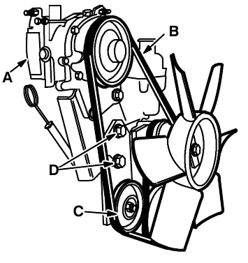
A. Governor
B. Belt
C. Idler
D. Idler Bolts
Static drag chain
A static drag chain is provided to prevent the buildup of static electricity in the machine. The chain is attached to the machine by a rear brush skirt retaining bolt.
The chain should make contact with the floor at all times.
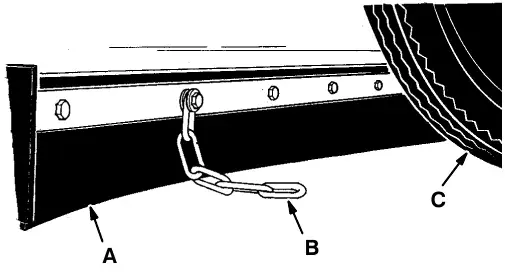
A. Rear Dust Skirt
B. Static Drag Chain
C. Rear Tire
Corrected an obvious misprint: the engine fan belt deflection was printed as “0.05 in (13 mm)” (now 0.5 in (13 mm), as for the governor belt on the same page).
Debris hopper
Hopper dust filter
The dust filter filters the air which is drawn up from the main brush compartment through the hopper. The dust filter is equipped with a shaker motor to remove the accumulated loose dust particles. The dust filter shaker motor is operated by the filter shaker switch. Shake the dust filter before dumping the hopper and at the end of every work shift. Inspect and clean or replace the dust filter after every 100 hours of operation.
To clean the dust filter, use one of the following methods:
- TAPPING – Tap the filter gently on a flat surface with the dirty side down. Do not damage the edges of the filter element or the filter will not seat properly in the filter frame.
- AIR – Blow compressed air, 35 psi (240 kPa) maximum, through the dust filter opposite the direction of the arrows. This may be done with the dust filter in the machine. Always wear eye protection when using compressed air.
- WATER – Soak the dust filter in a water and mild detergent solution. Rinse the dust filter until it is clean. The maximum water pressure allowable is 40 psi (275 kPa). Air dry the wet dust filter; do not use compressed air.
NOTE: Be sure the dust filter is dry before reinstalling it in the machine.
To remove hopper dust filter
- Stop the engine and set the machine parking brake.
- Release the hopper cover latches and remove the hopper cover.
- Disconnect the shaker motor wire connectors.
- Remove the four shaker frame nuts and shaker frame from the filter frame.
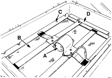
A. Filter Shaker Motor
B. Dust Filter
C. Frame Nut
D. Shaker Frame
- Lift the dust filter element out of the dust filter frame.
- Clean or discard the dust filter as required.
To install hopper dust filter
- Place the cleaned or new dust filter in the hopper dust filter frame with the arrows pointing up.
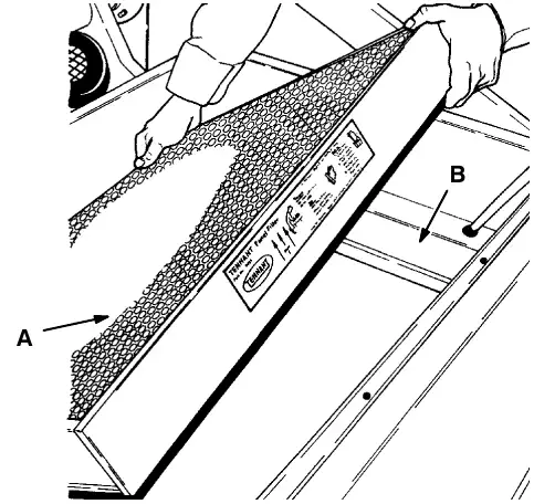
A. Dust Filter
B. Dust Filter Frame
- Position the shaker frame on top of the filter frame.
- Replace and tighten the shaker frame nuts.
- Position and secure the hopper cover on the hopper with the cover latches.
Debris hopper
The debris hopper collects the debris swept up by the machine. The low dump model hopper has one adjustment — floor clearance. The multi-level dump model hopper has five adjustments: lift linkage, lift cylinder, floor clearance, dump cylinders, and dump door latches. All of the adjustments have been made at the factory and require no regular maintenance. If the hopper components are repaired or replaced, the hopper must be readjusted for best performance.
The hopper adjustments must be made in the order given. Make all adjustments with the engine off and parking brake engaged. If the adjustments are made with the hopper raised, be sure to engage the hopper support bar.
To adjust low dump model hopper
NOTE: Empty the debris hopper before making adjustments.
1. FLOOR CLEARANCE ADJUSTMENT
A. Stop the engine and set the machine parking brake.
B. Slide a 0.75 to 0.88 in (20 to 25 mm) thick block under each of the rear metal corners of the hopper.
C. Check and adjust the cams on the lift arms so the hopper brackets rest on the cams.
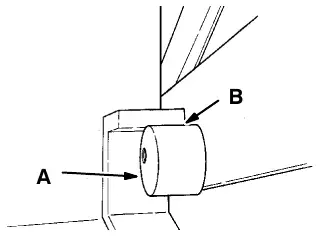
A. Cam
B. Hopper Bracket
To adjust multi-level dump model hopper
NOTE: Empty the debris hopper before making adjustments.
1. HOPPER LIFT LINKAGE ADJUSTMENT.
A. Stand clear and cycle the hopper up and down. Watch for signs of binding, sloppiness, or misalignment of the lift arm linkage. Reshim to remove binding, sloppiness, or misalignment of the linkage as necessary.
B. Stop the engine and set the machine parking brake.
C. Measure the distance from the center of each of the torque shafts to the floor with the hopper in the “operating” position.
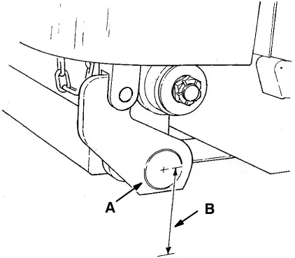
A. Torque Shaft
B. Measured Distance
The distance measured should be 6.43 ± 0.12 in (160 ± 5 mm). To adjust the height, remove one or both of the splined lift arm cams and rotate it or them until the proper dimension is achieved. The cams must rest on the sloping edge of the lintel.
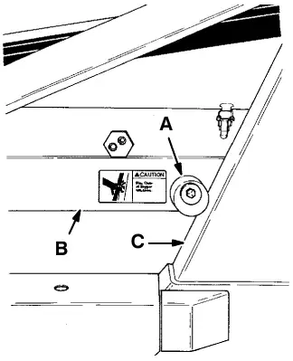
A. Lift Arm Cam
B. Lift Arm
C. Lintel
D. Tighten the lift arm cam bolt(s).
2. HOPPER LIFT CYLINDER ADJUSTMENT
A. Loosen the clevis jam nut on the cylinder rod.
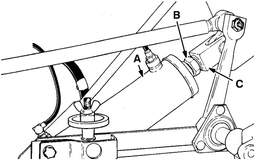
A. Hopper Lift Cylinder
B. Jam Nut
C. Cylinder Clevis
B. Adjust the cylinder clevis so the cylinder is fully retracted by inserting a pin through the cylinder rod and rotating it.
C. Tighten the clevis jam nut against the clevis.
3. HOPPER FLOOR CLEARANCE ADJUSTMENT
A. Remove the clevis pins connecting the clevis of the hopper dump cylinders to the torque arms.
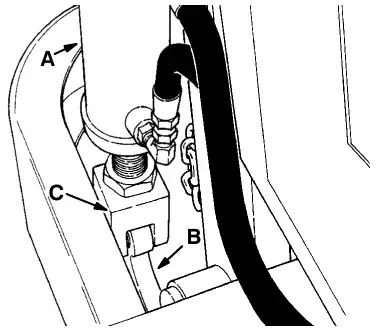
A. Hopper Dump Cylinder
B. Torque Arm
C. Clevis
B. Disconnect the dump cylinder clevis ends from the torque arms.
C. Place a 3.43 ± 0.12 in (90 ± 5 mm) block under each of the rear sides of the hopper.
D. Check and adjust, if necessary, the hexagon hopper cams on each side of the hopper so they contact the top surface of the hopper lift arms.
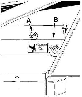
A. Hexagon Hopper Cam
B. Hopper Lift Arm
E. Tighten the hexagon hopper cam bolts.
F. Reconnect the dump cylinder clevises to the torque arms with the clevis pins removed earlier.
4. DUMP CYLINDERS ADJUSTMENT
A. Start the engine and completely retract the dump cylinders.
B. Stop the engine.
C. Loosen the cylinder clevis jam nuts.
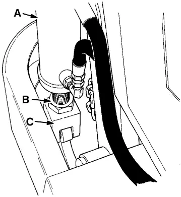
A. Hopper Dump Cylinder
B. Jam Nut
C. Cylinder Clevis
D. Remove clevis pin retaining rings and clevis pins.
E. Adjust the cylinder clevis so the dump cylinder clevis and torque arm, and the clevis pin holes align and allow the clevis pin to pass freely through them.
F. Tighten the clevis jam nuts.
G. Secure the clevis pins in place with their retaining rings.
5. DUMP DOOR LATCHES ADJUSTMENT
A. Start the engine and dump the hopper.
B. Return the hopper to the “operating” position. Stop the engine.
C. Check the hopper door latches to be sure they are engaged and the hopper door is closed tightly.
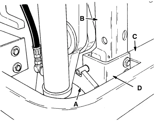
A. Hopper Dump Door Latch
B. Hopper Door
C. Bumper
D. Latching Bracket
D. Adjust latching action by adjusting latch stop bolt. Do not position stop bolt too high or the door will close too tightly and damage the seal and latches.
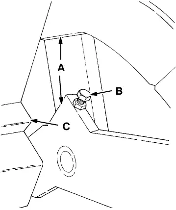
A. Lift Arm
B. Stop Bolt
C. Hopper
E. Shim the hopper door latching brackets to adjust the hopper door latch engagement and hopper door seal compression. Do not compress the seal too much or the door will close too tightly and damage the seal and latches.
F. Start the engine.
G. Dump the hopper and observe the unlatching of the hopper door. The latches should release at the same time. Adjust the latch chain eyebolts if necessary.
6. STABILIZER LEG
The machine stabilizer leg is a safety device which, when the machine is being high dumped, projects forward to act as an anti-tipping device. Check the stabilizer leg to be sure it is projecting forward when the machine is being high dumped and is fully retracted when the hopper is in the “operating” position. To adjust stabilizer leg:
A. Raise the hopper and engage the hopper support bar.
B. Stop the engine and set the machine parking brake.
C. Loosen the clevis jam nut.
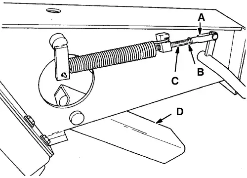
A. Clevis
B. Jam Nut
C. Threaded Rod
D. Stabilizer Leg
D. Thread the clevis onto the threaded rod to raise the stabilizer leg or thread the clevis off the threaded rod to lower the stabilizer leg.
E. Tighten the jam nut against the clevis.
F. Raise the hopper, disengage the hopper bar and lower the hopper.
G. Check the position of the stabilizer leg. Readjust as required.
Thermo Sentry™
The Thermo Sentry™ is a thermostat that senses the temperature of the air drawn into the vacuum fan from the hopper. It controls the solenoid valve which directs hydraulic fluid to the main brush and vacuum fan motors. If there is a fire in the hopper, the high air temperature causes the thermostat to trip, stopping electrical current to the solenoid valve. This stops the fan and main brush motors, cutting off air flow to the fire.
After the thermostat has tripped, it must be manually reset by pushing in its reset button.
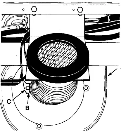
A. Vacuum Fan
B. Thermo Sentry™
C. Reset Button
Brushes
Main brush
The main brush is tubular and spans the width of the machine, sweeping debris into the debris hopper. It should be inspected daily for wear or damage. Remove any string or wire found tangled on the main brush, main brush drive hub, or main brush idler hub.
Rotate the main brush end-for-end after every 50 hours of operation for maximum brush life and best sweeping performance.
The main brush pattern should be checked daily. It should be 2.5 in (65 mm) wide for indoor applications and 3.5 in (90 mm) for outdoor applications with the main brush in the “normal” position. Main brush pattern adjustments are made by turning the height adjustment knob behind the side shroud next to the operator’s left leg.
The main brush should be replaced when the remaining bristles measure 1.25 in (30 mm) in length.
To replace main brush
- Stop the engine and set the machine parking brake.
- Place the main brush position lever in the (Main Brush Down) position.
- Open the right side main brush door.
- Remove the brush idler arm retaining bolt from the arm hub.
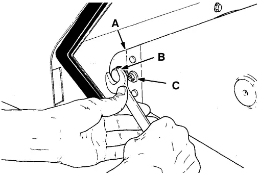
A. Brush Idler Arm
B. Arm Retaining Bolt
C. Plastic Screw
- Pull the brush idler arm off the arm hub.
NOTE: If the brush idler arm does not come off easily, remove the plastic screw located next to the brush idler arm retaining bolt. Thread the brush idler arm retaining bolt into the threaded hole where the plastic screw was mounted. Tighten the retaining bolt until it forces the brush idler arm loose. Remove the brush idler arm retaining bolt and reinstall the plastic screw.
- Grasp the main brush; pull it off the brush drive plug and out of the main brush compartment.
- Place the new or rotated end-for-end main brush on the floor next to the access door.
- Slide the main brush onto the drive plug. Rotate the brush until it engages the drive plug and push it all of the way onto the plug.
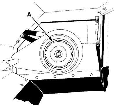
A. Brush Drive Plug
- Slide the main brush idler plug onto the main brush.
- Slide the brush idler arm onto the arm hub.
- Thread the brush idler arm retaining bolt through the idler arm and into the arm hub. Tighten the retaining bolt.
- Close the right side main brush door.
- Check and adjust the main brush pattern as described in TO CHECK AND ADJUST MAIN BRUSH PATTERN.
To check and adjust main brush pattern
- Apply chalk, or some other material that will not blow away easily, to a smooth, level floor.
- With the side brush and main brush raised, position the main brush over the chalked area.
- Place the hopper lift and side brush lever into the (Side Brush On) position, and the main brush, vacuum fan and filter shaker switch into the bottom (Main Brush On) position.
- Place the main brush position lever in the (Main Brush Down) position for 15 to 20 seconds while keeping a foot on the brakes to keep the machine from moving. This will lower the rotating main brush.
- Place the main brush position lever in the (Main Brush Up) position.
NOTE: If chalk or other material is not available, allow the brushes to spin on the floor for two minutes. A polish mark will remain on the floor.
- Drive the machine off the test area.
- Observe the width of the brush pattern. The proper brush pattern width is 2.5 in (65 mm) for indoor applications and 3.5 in (90 mm) for outdoor applications.
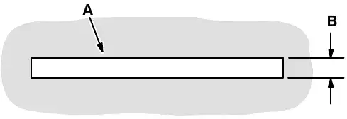
A. Main Brush Pattern
B. Pattern Width
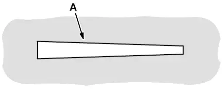
A. Main Brush Pattern
If the main brush pattern is tapered, more than 0.5 in (15 mm) on one end than the other, on a flat, level surface, first loosen the main brush left cross shaft bearing mounting brackets and the bearing flanges. Then pivot the bearing mounting bracket to level the cross shaft. Tighten the bearing mounting bracket and the bearing flanges. Check the main brush pattern and readjust as necessary. Then adjust the width of the main brush pattern.
To widen the main brush pattern, loosen the locking wing nut and turn the adjustment knob counterclockwise from the top. To reduce the width of the main brush pattern, loosen the locking wing nut and turn the adjustment knob clockwise from the top.
Tighten the locking wing nut and recheck the main brush pattern. Repeat the procedure until the main brush pattern is within the specified range.
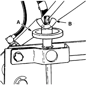
A. Height Adjustment Knob
B. Wing Nut
Side brush
The side brush sweeps debris from curbs or gutters into the path of the main brush. It should be inspected daily for wear or damage. Remove any string or wire found tangled on the side brush or side brush drive hub.
The side brush pattern should be checked daily. Between one-third and one-half of the side brush bristles should contact the floor when the brush is in motion. The side brush pattern adjustment on low dump model machines is made by loosening the two nuts on the side brush arm, repositioning the side brush assembly, and retightening the nuts.
The side brush should be replaced when the remaining brush bristle measures 2.5 in (65 mm) in length.
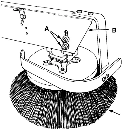
A. Nut
B. Side Brush Arm
C. Side Brush
The side brush pattern adjustment on multi-level dump model machines is made by loosening the two bolts on the side brush arm, repositioning the side brush assembly, and retightening the bolts.
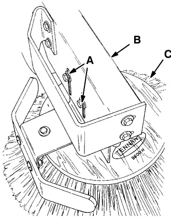
A. Bolt
B. Side Brush Arm
C. Side Brush
To replace side brush
- Empty the debris hopper.
- Raise the hopper, engage the hopper support bar, and lower the hopper onto the support bar.
- Stop the engine and set the machine parking brake.
- Place the side brush position lever in the (Side Brush Up) position.
- Remove the side brush retaining pin from the side brush hub and shaft by pulling the pin keeper off over the end of the pin.
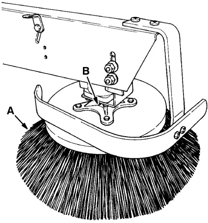
A. Side Brush
B. Retaining Pin
- Slide the side brush off the side brush drive shaft.
- Slide the new side brush onto the side brush drive shaft.
- Insert the side brush retaining pin through the side brush hub and shaft.
- Secure the pin by clipping the pin keeper over the end of the pin.
- Adjust the side brush pattern.
- Disengage the hopper support bar and lower the hopper.
Skirts and seals
Hopper lip skirts
The hopper lip skirts are located on the bottom rear of the hopper. They float over debris and help deflect that debris into the hopper. The hopper lip skirts are made up of five bottom lip segments and two additional side lip segments on multi-level dump model machines.
The hopper lip skirts should be inspected for wear or damage daily.
To replace hopper lip skirts
- Empty the machine debris hopper.
- Set the machine parking brake.
- Raise the hopper, engage the hopper support bar, and lower the hopper onto the hopper support bar.
- Stop the engine.
- Remove the hopper lip retaining strip mounting bolts.
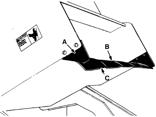
A. Hopper Lip Side Skirt
B. Retaining Strip
C. Hopper Lip Skirts
- Remove the hopper lip retaining strip and worn or damaged hopper lip.
- Thread the retaining strip mounting bolts through the retaining strip, the hopper lip segment, and into the hopper.
- Tighten the mounting bolts.
- Start the engine.
- Raise the hopper, lower the hopper support bar, and lower the hopper.
- Stop the engine.
Brush door skirts
The brush door skirts are located on the bottom of each of the two main brush doors. They seal the main brush compartment. They should clear the floor up to a maximum of 0.25 in (5 mm).
The skirts should be inspected for wear or damage and adjustment daily.
To replace and adjust brush door skirts
- Park the machine on a smooth, level surface.
- Stop the engine and set the machine parking brake.
- Open the main brush doors.
- Remove the brush door skirt retaining bolts.
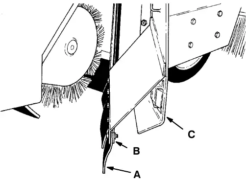
A. Brush Door Skirt
B. Skirt Retaining Strip
C. Brush Door
- Remove the skirt retaining strip and the door skirt.
- Position the new door skirt and skirt retaining strip on the brush door.
- Thread the skirt retaining bolts through the brush door, the door skirt, and into the skirt retaining strip.
NOTE: The brush door skirts have slotted holes to allow for a ground clearance adjustment. The door must be closed for proper adjustment.
- Slide the brush door skirt up or down so that the skirt clears the floor by 0.25 in (5 mm).
- Tighten the skirt retaining bolts.
- Close the brush doors.
Rear skirts
The rear skirts are located on the bottom rear of the main brush compartment. They seal the main brush compartment. They should clear the floor up to a maximum of 0.25 in (5 mm).
The seals should be inspected for wear or damage and adjustment daily.
To replace and adjust the rear skirts
- Park the machine on a smooth, level surface.
- Stop the engine and set the machine parking brake.
- Open the main brush doors.
- Remove the main brush as described in TO REPLACE MAIN BRUSH.
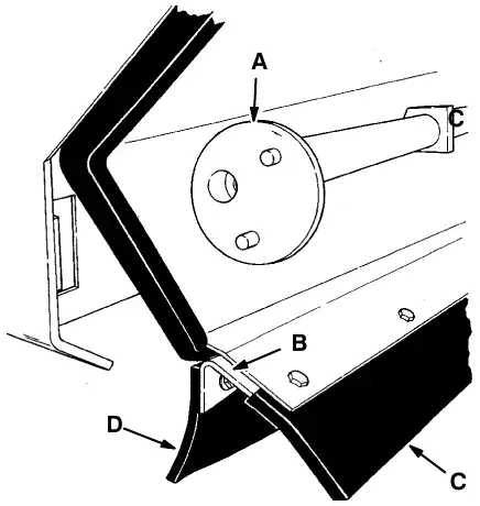
A. Brush Idler Arm Hub
B. Skirt Mounting Bracket
C. Rear Floor Skirt
D. Brush Contact Skirt
- Remove the skirt mounting bracket and the brush contact skirt.
- Remove the rear floor skirt from the skirt mounting bracket.
- Thread the rear floor skirt retaining strip mounting bolts through the retaining strip, the new rear floor skirt, and into the skirt mounting bracket.
- Do not tighten the mounting bolts at this time.
- Thread the retaining bolts through the skirt mounting bracket, the brush contact skirt, and into the machine frame.
- Tighten the retaining bolts.
- Slide the rear floor skirt up or down so that the skirt clears the floor up to a maximum of 0.25 in (5 mm).
- Tighten the rear floor skirt mounting bolts.
- Reinstall the main brush.
Main brush door seals
The main brush door seals are located on both main brush doors and on corresponding portions of the main frame. They seal the main brush compartment.
The seals should be inspected for wear or damage after every 100 hours of operation.
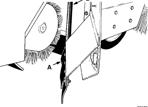
A. Brush Access Door
B. Door Seals
Hopper seals
The hopper seals are located on the top and side portions of the machine frame which contact the hopper. They seal the main brush compartment.
The seals should be inspected for wear or damage after every 100 hours of operation.
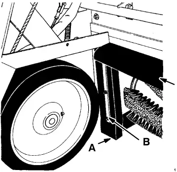
A. Side Seal
B. Seal Retaining Strip
C. Top Seal
Hopper inspection door seal
The hopper inspection door seal is located on the hopper inspection door on low dump model machines. It seals the front of the debris compartment.
The seal should be checked for wear or damage after every 100 hours of operation.
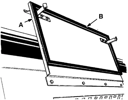
A. Hopper Inspection Door
B. Door Seal
Hopper door seals
The hopper door seals are located around the hopper door opening on multi-level dump model machines. They seal the hopper door.
The seals should be checked for wear or damage after every 100 hours of operation.
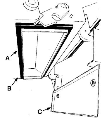
A. Seal
B. Hopper
C. Hopper Door
Hopper cover seal
The hopper cover seal is located on the top edges of the hopper. It seals the hopper filter compartment.
The seal should be checked for wear or damage after every 100 hours of operation.
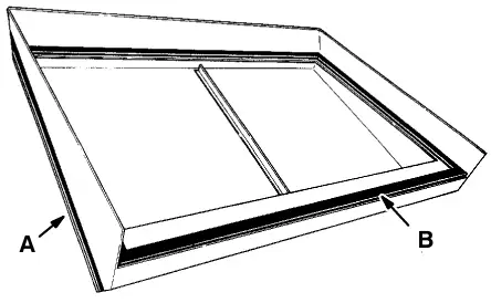
A. Hopper Cover
B. Cover Seal
Hopper vacuum fan seal
The hopper vacuum fan seal is mounted to the lintel on multi-level dump model machines. It seals the hopper filter compartment to the vacuum fan intake bracket.
The seal should be checked for wear or damage after every 100 hours of operation. Check to make sure that the seal is making good contact with the hopper. The seal should be compressed 0.12 in (3 mm) by the contact.
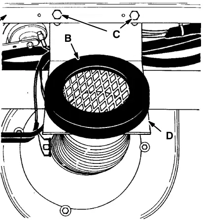
A. Lintel
B. Seal
C. Mounting Bolts
D. Bracket
To adjust seal contact, loosen the vacuum fan intake bracket mounting bolts. Pivot the bracket into the correct position and retighten the bolts.
Brakes and tires
Service brakes
The mechanical service brakes are located on the front wheels. They are operated by the foot brake pedal and connecting linkages.
The brake pedal should not travel more than 1 in (25 mm) to fully engage the brakes. Blow the accumulated dirt from between the brake shoes and the hub with compressed air through the slots on the side wheel pockets. Check the brake adjustment after every 200 hours of operation.
To adjust brake linkage
- Empty the debris hopper.
- Park machine on a level surface.
- Raise the hopper, engage the hopper support bar, and lower the hopper onto the support bar.
- Stop the engine.
- Block machine tires.
- Remove the clevis pins from the left and right side brake clevises.
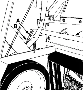
A. Brake Adjusting Clevis
B. Threaded Rod
C. Brake Cross Shaft
- Thread the clevis out to decrease brake pedal height, or in to increase brake pedal height. Both clevises must be turned the same amount.
- Adjust the brake linkage so that the brake pedal travels no more than 1 in (25 mm) to fully engage the brakes. If the brake pedal travels more than 1 in (25 mm), it indicates the brake clevises are not adjusted the same. Readjust as necessary.
- Reinstall the brake clevis pins.
- Start the engine and raise the hopper.
- Lower the hopper bar.
- Lower the hopper and stop the engine.
- Remove the machine tire blocks.
Parking brakes
The parking brakes are engaged by the parking brake lever which activates the service brake linkage.
The parking brakes should be adjusted whenever it becomes very easy to engage the parking brake, when the machine rolls after engaging the parking brake, and after every 200 hours of operation. The parking brake may be routinely tightened by turning the knurled knob on the end of the parking brake clockwise. If the knob adjustment is inadequate, fully loosen the knob and adjust the brake linkage as described in To Adjust Brake Linkage. Adjust the parking brake so it will hold the machine on a smooth 8° ramp.
Tires
The standard front machine tires are solid.
The standard rear machine tire is pneumatic.
Check the tire pressure after every 100 hours of operation. The proper tire air pressure is 80 ± 5 psi (550 ± 35 kPa). When the machine is equipped with a scrub attachment, the proper air pressure is 70 ± 5 psi (480 ± 35 kPa).
A solid rear tire is available as an accessory.
Scrub attachment
Scrub attachment
The scrub attachment accessory gives the machine the added flexibility to scrub floors. It consists of three groups of parts – the scrub attachment, the side scrub brush and squeegee, and the rear squeegee. The scrub attachment includes two solution tanks, a solution distribution system, three scrub brushes, a recovery tank, and a debris hopper.
Solution tanks
The two solution tanks supply the scrub brush with a water and detergent solution. They are located in the top right and left sides of the scrub attachment.
Access to the tanks is through the solution tank covers on the top of the scrub attachment.
The solution tanks require no regular maintenance. If detergent cakes on the bottom of the tank, remove the deposits with a strong blast of water.
Solution distribution system
The solution is distributed by feed lines from the solution tanks to an on-off solenoid valve, to a cable controlled flow-rate valve, then to a solution spreader tube.
The solution spreader tube distributes scrub solution to the scrub brushes. It may be flushed out if it becomes clogged. A drain plug is located on each end of the spreader tube.
Before cleaning the solution spreader tube, make sure that the cable controlled flow-rate valve is opening fully when the solution flow knob is pulled out.
A brush and hot water may be needed to remove stubborn clogs. A sharp instrument may be used to clear the small distribution holes in the spreader tube.
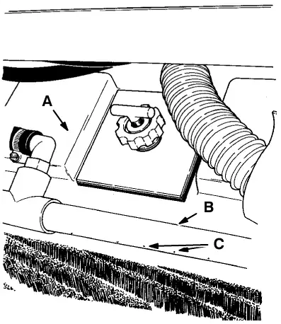
A. Recovery Tank
B. Spreader Tube
C. Distribution Holes
Scrub brushes
Three scrub brushes are utilized by the scrub attachment – the side brush, the main brush, and a scrub brush located in the scrub attachment. The side brush scrubs and deflects debris into the path of the scrub brush. The scrub brush scrubs and deflects debris backward, the main brush scrubs and deflects debris into the debris hopper.
The brushes should be inspected daily for damage or wear. Remove any string or wire found tangled on the scrub brushes, drive, or idler hubs.
Replace the scrub brushes when the brush bristle is 0.5 in (15 mm) or less in length. To replace the side brush, see TO REPLACE SIDE BRUSH. To replace the scrub brush, see TO REPLACE SCRUB BRUSH. To replace the main brush, see TO REPLACE MAIN BRUSH.
The scrub brush patterns should be checked daily. They should be 2 to 3 in (50 to 75 mm) wide. The scrub brush pattern is adjusted by changing the position of the clevis on the threaded stud of the lift linkage. See TO CHECK AND ADJUST SCRUB BRUSH PATTERN.
To replace scrub brush
- Start the engine, raise the scrub attachment, and set the hopper support bar.
- Stop the engine and set the machine parking brake.
- Remove the brush idler arm nut.
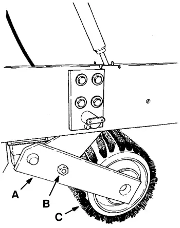
A. Idler Arm
B. Nut
C. Scrub Brush
- Pull the brush idler arm off the arm bracket.
- Pull the scrub brush off the drive hub.
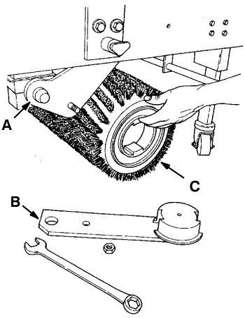
A. Bracket
B. Idler Arm
C. Scrub Brush
- Align the scrub brush drive slots with the drive keys on the drive nuts.
- Slide the scrub brush onto the drive hub.
- Slide the idler hub onto the scrub brush and arm bracket.
- Secure the idler arm with nut.
- Check and adjust scrub brush pattern as described in TO CHECK AND ADJUST SCRUB BRUSH PATTERN.
To check and adjust scrub brush pattern
- Apply chalk, or some other material that will not blow away easily, on a smooth, level floor.
- With the scrub brush position lever in the (Side Brush Up) position, move the scrub attachment over the test area. Set the parking brake.
- Press the main brush and vacuum fan switch.
- Place the scrub brush position lever in the “normal” position for 15 to 20 seconds, then return the lever to the “raised” position.
NOTE: If no chalk or other material is available, allow the brushes to spin approximately two minutes. It will make a polish mark on the floor.
- Press the main brush and vacuum fan switch.
- Release the parking brake and remove the machine from the test area.
- The scrub brush pattern should be 2 in (50 mm) across the full length of the brush.
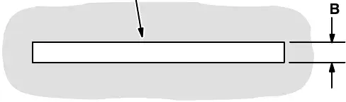
A. Scrub Brush Pattern
B. 2 in (50 mm)
To adjust the width of the pattern, adjust the position of the lift linkage clevis on the threaded stud. Thread the stud into the clevis to decrease the width. Thread the stud out of the clevis to increase the width.
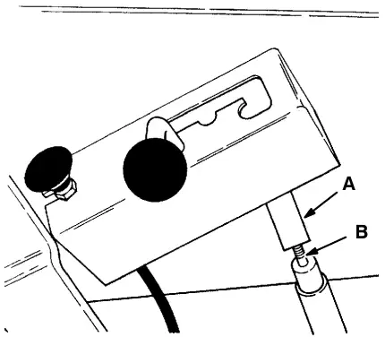
A. Clevis
B. Stud
If the brush pattern is tapered more than 0.25 in (5 mm), the scrub brush must be checked to see if it is cone shaped.
If the brush is not cone shaped, the scrub brush drive mechanism must be leveled by adding or removing shims between the scrub brush cross shaft bearing blocks and the scrub attachment frame.
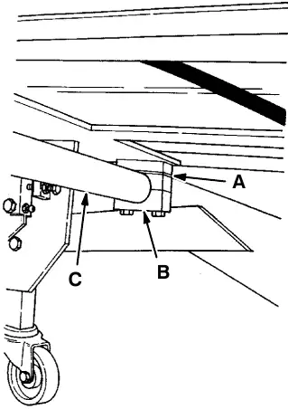
A. Shim
B. Bearing Block
C. Cross Shaft
Recovery tank
The machine recovery tank stores the water solution picked up by the machine squeegee and vacuum fan. The recovery tank is located under the solution tanks.
The recovery tank should be drained after the solution tank is empty and whenever the ball float rises and stops the water vacuum.
The recovery tank should be cleaned after every work shift.
Two clean-out doors have been provided to make the tank cleaning job easier. One door is located at the rear of the recovery tank. The other door is located at the front of the recovery tank.
Keep vacuum hoses and nozzles clean. Clogged hoses are a common cause of poor water pickup.
To drain the recovery tank
- Stop the engine and set the machine parking brake.
- Open the front access door.
- Remove the drain hose from its retention plug and lower it to a floor drain.
NOTE: The tank will not empty with the vacuum fan operating.
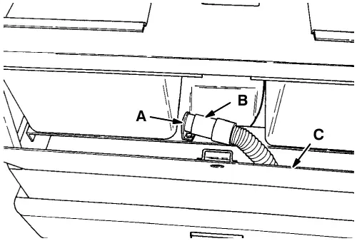
A. Retention Plug
B. Drain Hose
C. Front Access Door
To clean the recovery tank
- Stop the engine and set the machine parking brake.
- Drain the recovery tank.
- Open the front clean out doors by turning the door handles and pulling the doors away from the recovery tank.
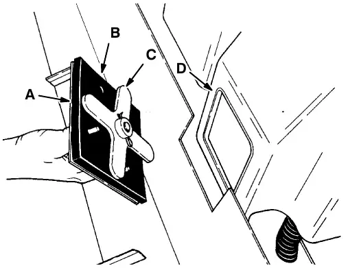
A. Clean-Out Door
B. Door Seal
C. Door Fingers
D. Recovery Tank
- Spray the inside of the tank with clean water. Remove all sludge and debris from the bottom of the tank.
- Spray the ball float. Make sure the float guides are free of dirt and debris which may cause the float to stick.
- Close the clean-out doors by positioning the doors against the recovery tank, turning the door handles so the four fingers line up behind the tank wall, and tighten the lock knob.
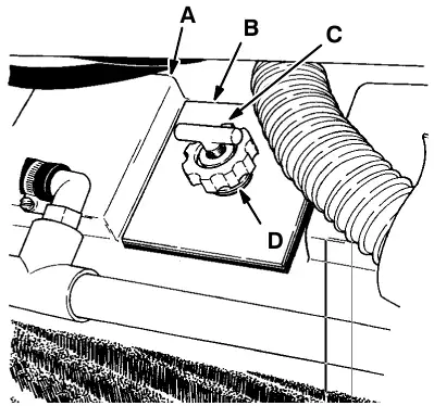
A. Recovery Tank
B. Clean-Out Door
C. Door Handle
D. Lock Knob
Debris hopper
The debris hopper collects debris picked up by the scrub brushes. It is located behind the scrub brushes.
A vacuumized debris screen is located on the bottom of the debris hopper to draw water solution out of the debris collected in the hopper.
The debris hopper should be emptied whenever the recovery tank is drained. It should be sprayed clean daily.
To empty the debris hopper, raise the scrub attachment with the hopper lift and side brush lever. The debris will empty as the unit is lifted and tilted back.
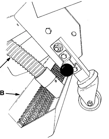
A. Vacuum Hose
B. Debris Hopper
The debris hopper is mounted by two pivoting points to allow it to float over large debris. It is equipped with float limiter. The lower limit bolt should be adjusted so the hopper has 0.3 in (10 mm) clearance with the floor. The upper limit bolt should be set so the hopper will travel up to a maximum of 1 in (25 mm) clearance.
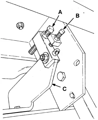
A. Lower Limit Bolt
B. Upper Limit Bolt
C. Debris Hopper
Side squeegee
The side squeegee controls water spray and channels water into the path of the rear squeegee. Check the side squeegee for damage, wear and adjustment daily. Replace the squeegee blade whenever it becomes damaged or loses its shape or resiliency.
To replace side squeegee blade
- Stop the engine and set the machine parking brake.
- Disconnect the squeegee assembly chain from the chain hook.
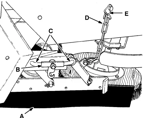
A. Squeegee Blade
B. Pin Keeper
C. Retaining Pin
D. Chain
E. Hook
- Pull the pin keeper out and remove the two squeegee assembly retaining pins. Release the pin keeper.
- Slide the squeegee assembly out of the machine.
- Remove the five squeegee retaining bolts from the squeegee assembly.
- Remove the squeegee blade from the squeegee frame.
- Position a new squeegee blade on the squeegee frame.
- Secure the blade with the blade retainer and retaining bolts.
- Slide the squeegee assembly into position in the squeegee bracket.
- Slide the two squeegee retaining pins through the bracket and squeegee assembly.
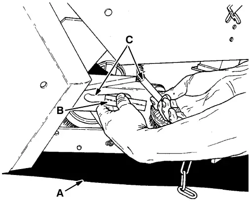
A. Squeegee Assembly
B. Pin Keeper
C. Pin
- Pull the pin keeper out, turn the squeegee retaining pins so they are under the pin keeper, and release the keeper.
- Connect the squeegee assembly chain to the chain hook.
Rear squeegee
The rear squeegee assembly channels water into the vacuum fan suction. The front squeegee blade channels the water, and the rear blade wipes the floor. Check the rear squeegee assembly for damage, wear, and adjustment daily.
Rotate or replace the front or rear blade of the rear squeegee if its leading edge is worn one-half of the way through the thickness of the blade.
Each front and rear blade has four wiping edges. To use them all, start with one wiping edge. To use the next wiping edge, swap the squeegee end-for-end. To use the next wiping edge, rotate the top edges down, bottom edges up. To use the last edge, swap the squeegee end-for-end. Replace the back-up strips if they become damaged, or if they lose their resiliency.
To replace or rotate rear blade
- Press the squeegee switch into the (Squeegee Down) position.
- Stop the engine and set the machine parking brake.
- Remove the retaining pin from each end of the squeegee. Remove the end brackets.
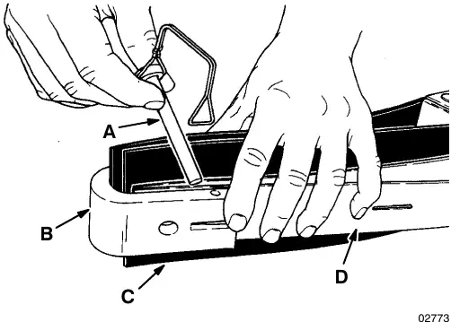
A. Retaining Pin
B. End Bracket
C. Squeegee Blade
D. Band
- Open the rear band clamp and remove the squeegee back-up strip and the squeegee blade.
- Replace or rotate the rear blade to allow a new edge of the blade to face the front of the machine.
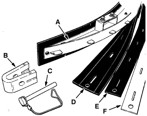
A. Frame
B. End Bracket
C. Retaining Pin
D. Blade
E. Back-Up Strip
F. Retaining Band
- Place the squeegee blade over the pins of the squeegee frame.
- Place the squeegee back-up strip on the pins.
- Position the squeegee retaining bands over the back-up strip.
- Replace the end brackets. Secure with the retaining pins.
- Adjust the rear squeegee as described in TO CHECK AND ADJUST REAR SQUEEGEE.
To replace or rotate front blade
- Press the squeegee switch into the "down" position.
- Stop the engine and set the machine parking brake.
- Disconnect the rear squeegee suction hose from the squeegee frame.
- Remove the two squeegee frame nuts and lower the squeegee assembly from the squeegee cross bar.
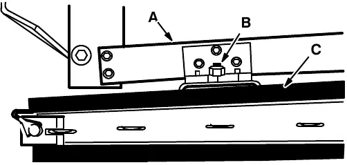
A. Cross Bar
B. Squeegee Frame Nut
C. Squeegee Assembly
- Remove the retaining pins from each end of the squeegee. Remove the end brackets.
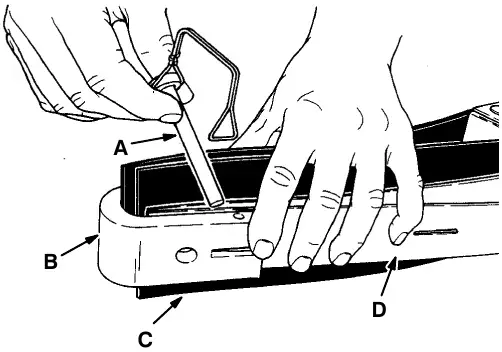
A. Retaining Pin
B. End Bracket
C. Squeegee Blade
D. Band
- Remove the hair cotter pin from the center of the front retaining band.
- Pull the retaining band, back-up strip, and squeegee blade off the squeegee frame.
- Replace or rotate the front blade to allow a new edge of the blade to face the front of the machine.
- Place the squeegee blade over the pins on the squeegee frame.
- Place the back-up strip on the pins.
- Position the ends of the retaining band in the slots at the ends of the squeegee frame.
- Press the center of the retaining band into place.
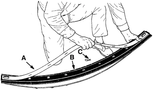
A. Retaining Band
B. Squeegee
C. Hair Cotter Pin
- Secure the retaining band with the hair cotter pin removed earlier.
- Replace the end brackets. Secure with the retaining pins.
- Lift the squeegee frame into position on the cross bar. Secure with the nuts removed earlier.
- Reconnect the squeegee suction hose to the squeegee frame.
To check and adjust rear squeegee
- Start the engine.
- Lower the squeegee and move the machine forward.
- Stop the engine and set the machine parking brake.
- Check the squeegee. It should contact the floor evenly side-to-side and deflect 0.88 in (20 mm) for smooth floors and 1.5 in (40 mm) for rough floors. If not, continue with step 5.
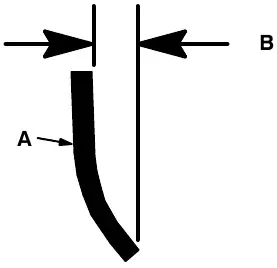
A. Squeegee
B. Deflection
NOTE: The squeegee blades must be new or have a new wiping edge contacting the floor to correctly adjust the squeegee.
- Check the squeegee lift cable. It should be loose when the squeegee actuator is in the extended "lower" position. The squeegee should clear the floor when the lever is in the retracted "lift" position.
- Start the engine, release the parking brake, raise and lower the squeegee. Then move the machine forward to deflect the squeegee blades.
- Stop the engine and set the machine parking brake.
- Level the squeegee from front to rear with the two squeegee adjustment bolts on the cross bar.
To lower the squeegee tips, thread the adjustment bolts counter-clockwise evenly on each side.
To raise the squeegee tips, thread the adjustment bolts clockwise evenly on each side.
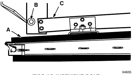
A. Squeegee Assembly
B. Adjustment Bolt
C. Cross Bar
- Adjust the squeegee deflection with the two squeegee adjustment studs.
To increase deflection, increase down pressure by adjusting the stud forward.
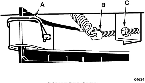
A. Squeegee
B. Stud
C. Jam Nut
To decrease deflection, decrease down pressure by adjusting the stud backward.
Loosen the jam nuts on both ends of the rods before making adjustments. Tighten the jam nuts after making any adjustments.
- Adjust the squeegee guards on each side of the machine so they clear the floor by 1.5 in (40 mm).
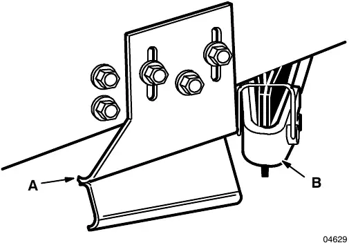
A. Guard
B. Squeegee
Snow broom
The snow broom accessory gives the machine the added flexibility to remove snow from walks and driveways. It consists of two groups of parts: The mounting frame, and the broom frame and drive assembly. The mounting frame is used to mount either the snow blade or snow broom assembly to the machine. The broom frame and drive assembly may be positioned so as to sweep snow to the left or right of the machine. Check the snow broom for tangled string or wire after each use. Replace the snow broom when the remaining bristles measure 1.25 in (30 mm) or less in length.
To replace snow broom
- Stop the engine and set the machine parking brake.
- Remove the bolt holding the idler arm to the cross shaft.
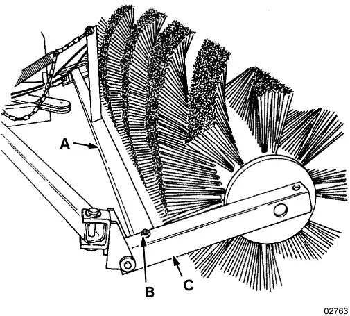
A. Cross Shaft
B. Bolt
C. Idler Arm
- Pull the idler plug out of the snow broom.
- Pull the snow broom off the drive plug.
- Slide the new snow broom onto the drive plug, making sure the drive keys and slots line up.
- Slide the idler plug into the snow broom.
- Secure the idler arm to cross shaft with the bolt.
Appendix contents
- Hardware information (printed page 4-3)
- Standard bolt torque chart (4-3)
- Metric bolt torque chart (4-3)
- Bolt identification (4-3)
- Thread sealant and locking compounds (4-3)
- Hydraulic fitting information (4-4)
- Hydraulic tapered pipe fitting (NPT) torque chart (4-4)
- Hydraulic tapered seat fitting (JIC) torque chart (4-4)
- Hydraulic O-ring fitting torque chart (4-4)
This page is blank in the printed manual.
Hardware information
The following charts state standard plated hardware tightening ranges for normal assembly applications. Decrease the specified torque by 20% when using a thread lubricant. Do not substitute lower grade hardware for higher grade hardware. If higher grade hardware than specified is substituted, tighten only to the specified hardware torque value to avoid damaging the threads of the part being threaded into, as when threading into speed nuts or weldments.
Standard bolt torque chart
| Thread size | SAE Grade 5 Torque ft lb (Nm) | SAE Grade 8 Torque ft lb (Nm) |
|---|---|---|
| 0.25 in | 7–10 (9–14) | 10–13 (14–18) |
| 0.31 in | 15–20 (20–27) | 20–26 (27–35) |
| 0.38 in | 27–35 (37–47) | 36–47 (49–64) |
| 0.44 in | 43–56 (58–76) | 53–76 (72–103) |
| 0.50 in | 65–85 (88–115) | 89–116 (121–157) |
| 0.62 in | 130–170 (176–231) | 117–265 (159–359) |
| 0.75 in | 215–280 (291–380) | 313–407 (424–552) |
| 1.00 in | 500–650 (678–881) | 757–984 (1026–1334) |
NOTE: Decrease torque by 20% when using a thread lubricant.
Metric bolt torque chart
| Thread size | Class 8.8 Torque ft lb (Nm) | Class 10.9 Torque ft lb (Nm) |
|---|---|---|
| M4 | 2 (3) | 3 (4) |
| M5 | 4 (5) | 6 (8) |
| M6 | 7 (9) | 10 (14) |
| M8 | 18 (24) | 25 (34) |
| M10 | 32 (43) | 47 (64) |
| M12 | 58 (79) | 83 (112) |
| M14 | 94 (127) | 133 (180) |
| M16 | 144 (195) | 196 (265) |
| M20 | 260 (352) | 336 (455) |
| M24 | 470 (637) | 664 (900) |
NOTE: Decrease torque by 20% when using a thread lubricant.
Exceptions to the above chart:
Check the machine for exceptions!
Bolt identification

| Grade marking (top to bottom) | Specification and grade |
|---|---|
| 1st marking | SAE–Grade 5 |
| 2nd marking | SAE–Grade 8 |
| 3rd marking | ISO–Grade 8.8 |
| 4th marking | ISO–Grade 10.9 |
Thread sealant and locking compounds
Thread sealants and locking compounds may be used on this machine. They include the following:
Locktite 515 sealant – gasket forming material. TENNANT® Part No. 75567, 15 oz (440 ml) cartridge.
Locktite 242 blue – medium strength thread locking compound. TENNANT® Part No. 32676, 0.5 ml tube.
Locktite 271 red – high strength thread locking compound. TENNANT® Part No. 19857, 0.5 ml tube.
Corrected an obvious misprint: SAE Grade 8, 0.25 in, printed as "10–13 (14–38)" (now 10–13 (14–18), since 10–13 ft lb converts to about 14–18 Nm, as in every other row).
Hydraulic fitting information
Hydraulic tapered pipe fitting (NPT) torque chart
NOTE: Ratings listed are when using teflon thread seal.
| Size | Minimum torque | Maximum torque |
|---|---|---|
| 1/4 NPT | 10 ft lb (14 Nm) | 30 ft lb (41 Nm) |
| 1/2 NPT | 25 ft lb (34 Nm) | 50 ft lb (68 Nm) |
| 3/4 NPT | 50 ft lb (68 Nm) | 100 ft lb (136 Nm) |
Hydraulic tapered seat fitting (JIC) torque chart
| Tube O.D. (in) | Thread size | Maximum torque |
|---|---|---|
| 0.25 | 0.44–20 | 9 ft lb (12 Nm) |
| 0.38 | 0.56–18 | 20 ft lb (27 Nm) |
| 0.50 | 0.75–16 | 30 ft lb (41 Nm) |
| 0.62 | 0.88–14 | 40 ft lb (54 Nm) |
| 0.75 | 1.12–12 | 70 ft lb (95 Nm) |
| 1.0 | 1.31–12 | 90 ft lb (122 Nm) |
Hydraulic O-ring fitting torque chart
| Tube O.D. (in) | Thread size | Minimum torque | Maximum torque |
|---|---|---|---|
| 0.25 | 0.44–20 | 6 ft lb (8 Nm) | 9 ft lb (12 Nm) |
| 0.38 | 0.56–18 | 13 ft lb (18 Nm) | 20 ft lb (27 Nm) |
| *10 ft lb (14 Nm) | 12 ft lb (16 Nm) | ||
| 0.50 | 0.75–16 | 20 ft lb (27 Nm) | 30 ft lb (41 Nm) |
| *21 ft lb (28 Nm) | 24 ft lb (33 Nm) | ||
| 0.62 | 0.88–14 | 25 ft lb (34 Nm) | 40 ft lb (54 Nm) |
| 0.75 | 1.12–12 | 45 ft lb (61 Nm) | 70 ft lb (95 Nm) |
| 1.0 | 1.31–12 | 60 ft lb (81 Nm) | 90 ft lb (122 Nm) |
NOTE: Do not use sealant on o-ring threads.
*Aluminum bodied components
Tennant and Nobles are trademarks of Tennant Company. Southeastern Equipment & Supply is an independent dealer.