User Manual Armadillo 9X Sweeper
Models: 9X & 9XCE
PowerBoss®, Minuteman International, Inc.
A Member of the Hako Group
#4100033 Rev. G 03/22
PREFACE
Thank you for your purchase of the new industry standard for sweepers. Minuteman International, Inc. takes great pride in offering the most dependable, reliable, and best value in industrial power sweepers and scrubbers. We set the standard.
Our Customer Service Department would like to hear from you. If you see any errors, omissions or something that needs clarification in this User Manual, please let us know. We are working hard towards continually improving our processes--to benefit you, our valued customer.
Thank you!
The PowerBoss® Team
PowerBoss®, Minuteman International, Inc.
14N845 U.S. Route 20
Pingree Grove, Illinois 60140 USA
Phone: (800) 323-9420
Email: [email protected]
www.PowerBoss.com
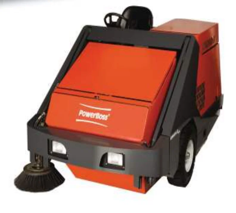
This is the User Manual for the PowerBoss® Armadillo 9X & 9XCE Series Sweeper.
This manual covers the Armadillo 9X & 9XCE machine variations beginning July 2015.
We believe this machine will provide excellent service for many years.
However, the best results will be obtained if:
- The machine is operated with reasonable care.
- The machine is maintained regularly per the maintenance schedule provided in this User Manual.
- The machine is maintained with PowerBoss® supplied or equivalent parts.
All right side and left side references to the machine (except for engine) are determined by facing the direction of forward travel. The front of the engine or engine fan faces the rear of the machine. Some hardware considered to be common or locally available has been omitted from the parts section to make this manual clear. Be sure to use equivalent hardware when replacement becomes necessary.
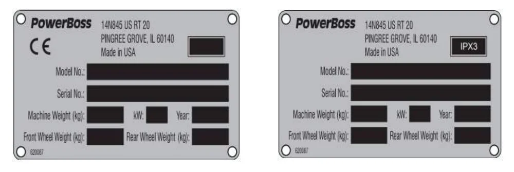
The Model and Serial Number of your machine is shown on the I.D. name plate. This information is needed when contacting Technical Support or when ordering parts. The I.D. plate is mounted on the console of the machine, left of the operator and adjacent the main broom adjustment access door.
Parts may be ordered by phone, fax, or email from any PowerBoss® parts and service center. Before ordering parts or supplies, be sure to have your machine model number and serial number handy. For your convenience Fill out the data block on the next page for future reference.
Example I.D. Plates:
| MACHINE DATA Fill out at installation | |
|---|---|
| Serial Number: | ___________________________________ |
| Engine Serial Number: | ____________________________ |
| Sales Rep.: | ______________________________________ |
| Date of Install: | ___________________________________ |
All information contained in this manual is current at the time of printing. Minuteman International, Inc. reserves the right to make changes at any time without notice.
PowerBoss®, Minuteman International, Inc., Printed in USA ©2014-2015.
TECHNICAL SPECIFICATIONS
| Model | Model No |
|---|---|
| Armadillo 9X Series | SW9XKDSL, SW9XKGAS, SW9XKLPG |
| Armadillo 9X CE Series | 9XRDSLCE, 9XRLPGCE |
DIMENSIONS & WEIGHT
| Item | Value |
|---|---|
| Length | 105 in (267 cm) |
| Width | 60 in (152 cm) |
| Height (machine) | 52.5 in (133 cm) |
| Height (w/steering wheel) | 58 in (147 cm) |
| w/ Overhead guard | 81 in (206 cm) |
| w/ Cab | 81 in (206 cm) |
| Weight (Diesel engine) | 4090 lb (1855 kg) |
| Weight (Gas & LPG engines) | 4070 lb (1846 kg) |
| Minimum U-turn | 110 in (280 cm) |
SWEEPING SYSTEM
| Item | Value |
|---|---|
| Productivity | 184,800 ft²/hr (17,168 m²/hr) |
| Sweep path | 62 in (157 cm) |
| Main broom | 48 in (122 cm) |
| Side broom | 24 in (61 cm) |
| w/ Dual side broom | optional 72 in path optional (183 cm) path |
| Hopper type | RTR™ high dump |
| Hopper volume | 21.1 ft³ (0,59 m³) |
| Hopper load capacity | 1100 lb (498 kg) |
| Dust control | 110 ft² (10,22 m²) |
| High dump | 64 in (162 cm) includes RTR™(Rotary Trash Relocation) |
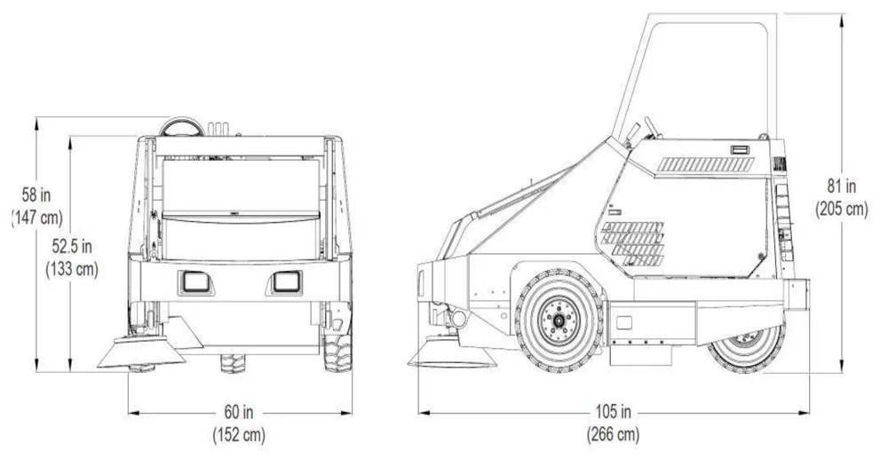
dimensions shown in inches (cm)
TABLE OF CONTENTS
| Section | Page |
|---|---|
| PREFACE | 3 |
| TECHNICAL SPECIFICATIONS | 6 |
| SWEEPING SYSTEM | 6 |
| FEATURES | 12 |
| AIR-MOVING SYSTEM | 13 |
| ERGONOMICS SYSTEM | 13 |
| DEBRIS-HANDLING SYSTEM | 13 |
| DRIVE-TRAIN SYSTEM | 13 |
| CHASSIS SYSTEM | 14 |
| POWERBOSS® INNOVATIONS | 14 |
| ENVIRONMENTAL FRIENDLY FEATURES | 15 |
| CLEAN AIR | 15 |
| LOWER EMISSIONS | 15 |
| SAFER WORK ENVIRONMENT | 15 |
| CLEAN ENERGY | 15 |
| SAFETY INFORMATION | 16 |
| IMPORTANT SAFETY INSTRUCTIONS | 16 |
| SAFETY DURING OPERATION | 16 |
| SERVICING OR MAINTAINING MACHINE | 17 |
| SAFETY SYMBOLS | 17 |
| SAFETY DECALS | 18 |
| BASIC POWERBOSS® SAFETY | 20 |
| MACHINE OPERATION | 24 |
| BASIC OPERATING CONTROLS & INDICATORS | 24 |
| IGNITION SWITCH | 24 |
| THROTTLE SWITCH (GAS AND LPG ONLY) | 24 |
| GLOW PLUG SWITCH (DIESEL ONLY) | 24 |
| THROTTLE CONTROL (DIESEL ONLY) | 24 |
| LIGHT SWITCH | 26 |
| HOUR METER | 26 |
| HORN BUTTON | 26 |
| AUTOMATIC DIESEL SHUTOFF SWITCH | 26 |
| HOPPER FILTER SHAKER BUTTON | 26 |
| FUEL LEVEL GAUGE (DIESEL AND GAS ONLY) | 26 |
| VOLTMETER GAUGE | 26 |
| ENGINE OIL PRESSURE GAUGE | 26 |
| ENGINE COOLANT TEMPERATURE GAUGE | 26 |
| CIRCUIT BREAKER | 26 |
Table of Contents
| Topic | Page |
|---|---|
| DIRECTIONAL CONTROL PEDAL | 27 |
| PARKING BRAKE | 27 |
| BRAKE PEDAL | 27 |
| TILT STEERING LEVER | 27 |
| DUAL SIDE BROOM SWITCH | 28 |
| FIRE IN THE HOPPER LIGHT | 28 |
| CLOGGED FILTER LIGHT | 28 |
| CHECK ENGINE LIGHT | 28 |
| SWEEPING CONTROLS | 29 |
| BROOM CONTROL LEVER | 29 |
| MAIN BROOM HANDLE | 29 |
| SIDE BROOM HANDLE | 29 |
| DEBRIS HOPPER DUMP CONTROLS | 30 |
| HOPPER FILTER SHAKER BUTTON | 30 |
| HIGH DUMP | 30 |
| LEVER 1 | 30 |
| LEVER 2 | 30 |
| TO RAISE AND DUMP THE HOPPER: | 31 |
| ROTARY TRASH RELOCATOR (RTR™) | 31 |
| OPERATING PROCEDURES | 32 |
| PRE-OPERATION CHECKS | 32 |
| STARTING | 32 |
| SLOWING AND STOPPING | 33 |
| OPERATING ON GRADES | 33 |
| SWEEPING | 33 |
| EMPTY HOPPER WITH HIGH DUMP FEATURE | 34 |
| ROTARY TRASH RELOCATOR (RTR™) | 35 |
| TRANSPORTING THE MACHINE | 36 |
| Using a Trailer or Transport Vehicle | 36 |
| Pushing the Machine | 36 |
| OPTIONS | 37 |
| NEUTRAL START SENSOR | 37 |
| OPERATOR SEAT SENSOR | 37 |
| SECOND HAND OPERATION PUSHBUTTON | 38 |
| RAISE HOPPER - MAIN BROOM SHUT OFF | 38 |
| AUTOMATIC DIESEL SHUTOFF SWITCH | 39 |
| LOW LP INDICATOR | 39 |
| PARKING BRAKE BYPASS SWITCH | 40 |
| Topic | Page |
|---|---|
| AIR CONDITIONING | 40 |
| HEATER | 41 |
| VACUUM WAND | 42 |
| BLOWER WAND | 43 |
| DUAL CURB BROOM | 43 |
| DUST SUPPRESSION SYSTEM | 44 |
| SEAT BELTS | 44 |
| LIGHTS | 44 |
| SUSPENSION SEAT | 45 |
| PREVENTATIVE MAINTENANCE | 47 |
| INTRODUCTION | 47 |
| SCHEDULED MAINTENANCE CHART | 48 |
| PREVENTATIVE MAINTENANCE INSTRUCTIONS | 52 |
| ENGINE | 52 |
| AIR INTAKE SYSTEM | 52 |
| Check Air Filter Service Indicator | 52 |
| Air Filter Element Removal | 53 |
| Air Filter Cleaning | 53 |
| Air Filter Inspection | 54 |
| Air Filter Installation | 54 |
| Topic | Page |
|---|---|
| ELECTRICAL SYSTEM | 55 |
| Battery Cleaning | 55 |
| Battery Replacement | 55 |
| Circuit Breaker | 56 |
| Fuses | 56 |
| FUEL SYSTEM | 57 |
| COOLANT SYSTEM | 59 |
| Blowing Out Radiator Fins | 59 |
| Reverse Flow Flushing | 59 |
| LUBRICATION | 59 |
| Changing Engine Oil | 59 |
| LUBRICATION POINTS | 60 |
| Steering Cylinder | 60 |
| Engine Mount Pivot | 60 |
| Latches & Hinges | 61 |
| Hopper Lift Arm Mounts | 61 |
| HYDRAULICS SYSTEM | 63 |
| Filling The Fluid Reservoir | 63 |
| Hydraulic Fluid Viscosity Specifications | 63 |
| Maintaining Hydraulic Oil Cooler Efficiency | 63 |
| Changing The Hydraulic Fluid | 63 |
Table of Contents
| Topic | Page |
|---|---|
| Changing The Hydraulic Fluid Filter | 64 |
| Adjusting The Directional Control Return Spring | 64 |
| SWEEP COMPONENTS | 65 |
| Broom Door Flap Inspection | 65 |
| Broom Door Flap Replacement and Adjustment | 65 |
| Main Broom Adjustment | 66 |
| Main Broom Height Adjustment | 67 |
| Main Broom Taper Adjustment | 67 |
| Main Broom Replacement | 68 |
| Side Broom Angle Adjustment | 69 |
| Side Broom Height (Wear) Adjustment | 69 |
| Adjust Side Broom Height | 69 |
| Side Broom Lift Cable Adjustment | 70 |
| Side Broom Replacement | 71 |
| HOPPER | 71 |
| High Dump Hopper Removal | 71 |
| High Dump Hopper Replacement | 72 |
| Floor Clearance and Dump Angle Adjustment | 73 |
| Hopper Filter Removal (Dual Filter) | 77 |
| Filter Cleaning | 78 |
| Filter Replacement | 78 |
| Vacuum Gasket Mount Adjustment | 79 |
| Flap Replacement | 79 |
| Frame Seal Replacement | 80 |
| Front Frame Seal | 80 |
| Side Frame Seal | 80 |
| PARKING BRAKE | 80 |
| Adjusting The Parking Brake Cable Length | 81 |
| TIRES | 82 |
| Changing Solid Tires | 82 |
| Changing Pneumatic Tires | 82 |
| MISCELLANEOUS ADJUSTMENTS | 83 |
| Anti-Static Chain Adjustment | 83 |
| Latch and Hinge Maintenance | 83 |
| Cables | 83 |
| TROUBLESHOOTING | 84 |
| TROUBLESHOOTING CHART | 84 |
| NOTES | 91 |
| CE DECLARATION OF CONFORMITY | 92 |
FEATURES
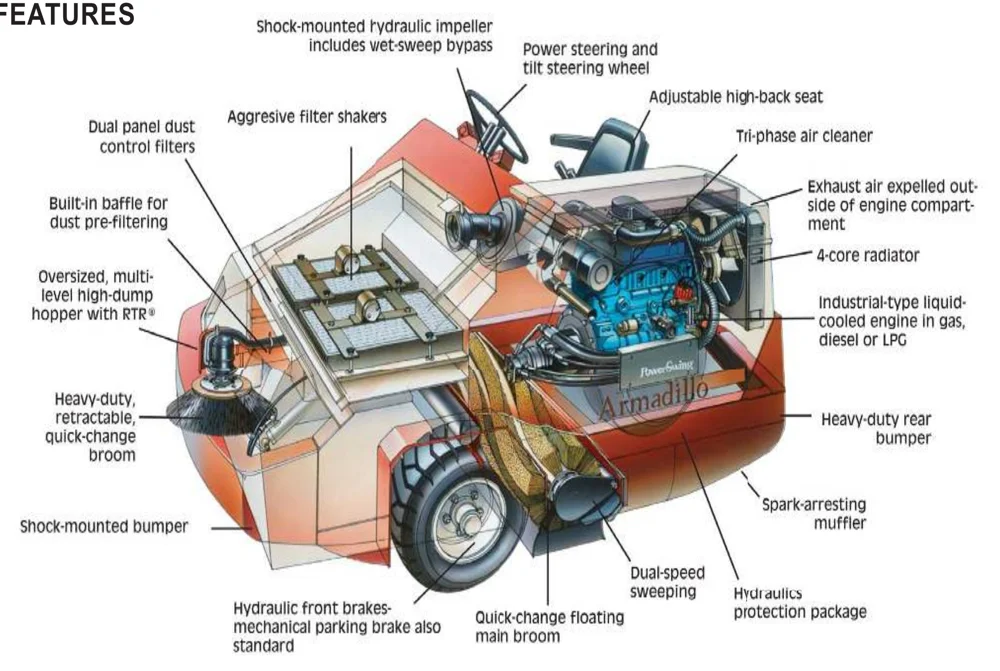
AIR-MOVING SYSTEM
- Dual-phase dust filtration
- Built-in pre-filtering & ultra-fine screen panel filters for dust control
- Aggressive electric filter shakers
- Shock-mounted hydraulic impeller
- Engine area shielded from exhaust air
- Dust Control Filter: 104 ft² (9,66 m²) total
- Timed Electric Filter Shakers
- Clogged Filter Indicator
- Fire-in-hopper Indicator
ERGONOMICS SYSTEM
- Roomy, open cockpit with extra comfort
- Adjustable, high-back seat
- Power steering and tilt steering wheel
- Comfortable pedal/controls placement
- Full instrumentation for all functions
DEBRIS-HANDLING SYSTEM
- Direct throw sweeping method
- Oversized hopper with RTR™
- Quick-change, floating 48 in (122 cm) main broom & retractable side brooms
- Dual-performance sweep mode
- Multi-Level Hopper Dumping
DRIVE-TRAIN SYSTEM
- Industrial liquid-cooled engine
- Heavy-duty radiator & Tri-phase air cleaner
- Hydraulics protection package
- PowerSwingTM engine access for ease of maintenance
- 4-Core Radiator
- PowerClimb™ All-Terrain Access
(2) - 23 in (58 cm) OD Pneumatic Front Tires
(1) - 21 in (53 cm) OD Pneumatic Rear Tire
CHASSIS SYSTEM
- Massive One-Piece, unitized steel frame
- Oversized, soft-ride tires
- PowerFlex™ automotive-type suspension on rear wheel (optional on some models)*
- Eliminates jolts and vibration for component protection*
POWERBOSS® INNOVATIONS
- PowerSwing™ - a patented system that allows you to rotate the engine out of the body of the sweeper for bench-like maintenance access to all parts.
- PowerClimb™ - with oversized tires and extra ground clearance you can easily negotiate rough terrain and speed bumps; even climb sidewalk curbs.
- PowerFlex™ - automotive-type rear wheel suspension that minimizes vibration for operator comfort and longer machine life.
ENVIRONMENTAL FRIENDLY FEATURES
CLEAN AIR
High-performance filter system dramatically reduces the release of dust and debris back into the air, dust vacuum ensures that dust is put directly into the hopper, bristle pattern on main broom increases dust control
LOWER EMISSIONS
All gas and LP engines meet EPA and CARB specifications and have catalyst mufflers. Diesel operation is available, bio-diesel fuel can be used in Kubota engines.
SAFER WORK ENVIRONMENT
Machines are highly visible to others in the workplace, simple controls reduce operator error, one-button scrub, horn, fire in hopper indicator, effective braking system, seat equipped with safety shut-off switch, also available: overhead guard, back-up alarm, warning beacon.
CLEAN ENERGY
Bio-diesel fuel can be used in Kubota engines.
SAFETY INFORMATION
IMPORTANT SAFETY INSTRUCTIONS
Operators must read and understand this manual before operating or maintaining this machine.
Do not operate this machine in flammable or explosive areas.
This machine is designed solely for removing dirt, dust and debris in an outdoor or indoor environment. PowerBoss® does not recommend using this machine in any other capacity.
The following information below may cause a potential hazard to the operator and equipment. Read this manual carefully and be aware when these conditions can exist. Take necessary steps to locate all safety devices on the machine and train the personnel operating the machine. Report any machine damage or faulty operation immediately. Do not use machine if it is not in proper operating condition.
SAFETY DURING OPERATION
Keep hands and feet clear of moving parts while machine is in operation.
Make sure all safety devices are in place and operate properly. All covers, doors and latches must be closed and fastened before use.
During operation, attention should be paid to other persons in the work area and especially if small children are present.
Components can cause an explosion when operated near explosive materials or vapor. Do not operate this machine near flammable materials such as solvents, thinners, fuels, grain dust, etc.
Store or park this machine on a level surface only. To prevent unauthorized use, machine should be stored or parked with the key removed.
This machine is designed for level operation only. Do not operate on ramps or inclines greater than 2%.
This machine is not suitable for picking up hazardous dusts.
Use caution when moving this machine into areas that are below freezing temperatures.
SERVICING OR MAINTAINING MACHINE
Stop on level surface.
Disconnect the power to the machine when servicing.
Avoid moving parts. Do not wear loose jackets, shirts, or sleeves when working on machine.
Avoid contact with battery acid. Battery acid can cause burns. When working on or around batteries, wear protective clothing and safety glasses. Remove metal jewelry. Do not lay tools or metal objects on top of battery.
Authorized personnel must perform repairs and maintenance. Use PowerBoss® supplied replacement parts.
SAFETY SYMBOLS
Five symbols are used throughout this manual to emphasize various levels of safety information. These symbols and the meaning of each are listed below.
SAFETY DECALS
Decals directly attached to various parts of the sweeper are highly visible safety reminders which should be read and observed. Make sure the decals are replaced if they become illegible or damaged.
Symbols at the top of the list are the strongest warnings. However, all symbols represent important information which should be observed to protect you and others from harm and injury, and to prevent damage to the equipment.
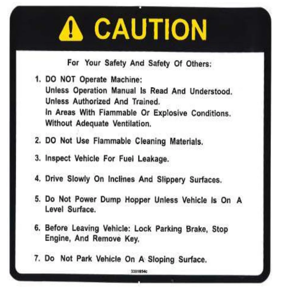
Located in the drive compartment:
Part Number 3301854
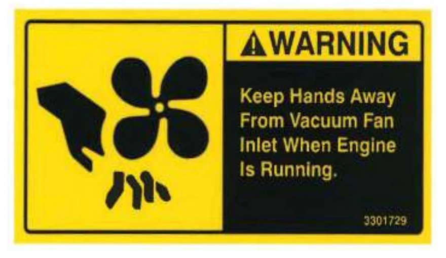
Located at the Impeller:
Part Number 3301729
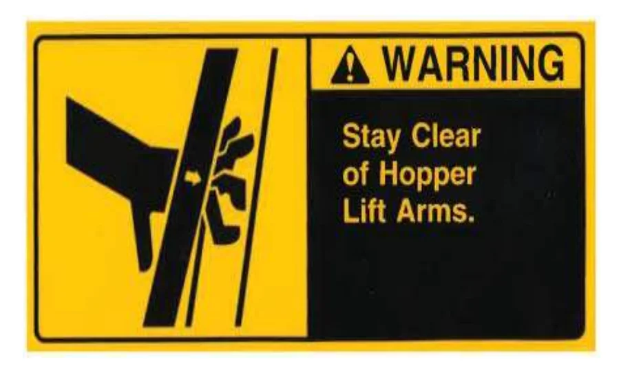
Located on the High Dump Hopper:
Part Number 3301732
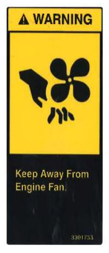
Located on the shroud of the radiator:
Part Number 3301733
BASIC POWERBOSS® SAFETY
PowerBoss® sweepers should never be operated unless:
- The operator is trained and authorized to operate the equipment and,
- The equipment is free of malfunctions. Malfunctioning equipment should be removed from service.
- You are securely seated in the operator’s seat.
- The parking brake is locked.
- The directional control pedal is in neutral.
- The throttle is in idle.
- Hydraulic controls are in the OFF position.
- Keep your hands and body clear of moving parts, especially when the hopper or lift arms are partially or fully raised.
- Make sure others in the area stay clear of the equipment and moving parts.
- Never attempt to dump debris from a dock or mezzanine. Dump from ground level only.
- Place the controls in the OFF position.
- Set the parking brake.
- Shut off the engine.
- Work in a properly ventilated area, do not smoke or allow an open flame near the fuel system.
- Never bypass safety components unless you are testing them.
- Never bypass the fuel filter lock, except when testing them (and always reconnect them after testing).
- Wear gloves to disconnect the tank coupling.
- Always stop the engine and set the parking brake before servicing.
- Never use detergents or cleansers that are flammable or combustible.
- Never inflate a pneumatic tire without using a safety cage.
- Do not attempt any impeller adjustment unless you have shut off the engine. Never place your hands near the intake hoses or inlet when the engine is running.
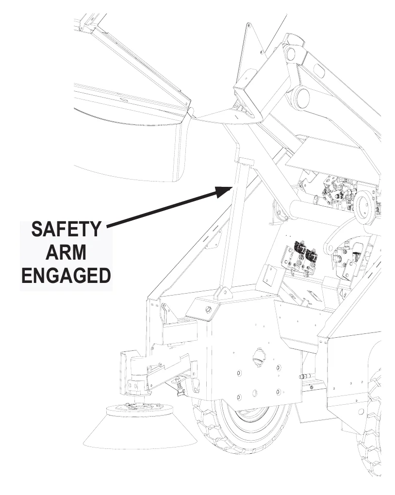
- Always engage the safety arm before servicing the hopper. Do not rely on the hydraulic cylinder to keep the hopper raised.
- Never test for hydraulic hose leaks using your hand or any other part of your body. High pressure leaks can be very dangerous and should only be checked using a piece or paper.
MACHINE OPERATION
BASIC OPERATING CONTROLS & INDICATORS
IGNITION SWITCH
The Ignition Switch for this machine has three key positions: “Off”, “On”, & “Start” position.
Starting Gas and LPG engines: From the “Off” position, turn the key clockwise to “On”, then continue to the “Start” position. When the engine starts, release the key. To stop the engine, turn the key counter-clockwise to the “Off” position.
Starting diesel engines: From the “Off” position, turn the key clockwise to the “On” position (do not try to start). Press down and hold the Glow Plug Switch for 10-12 seconds, release the Glow Plug Switch. Turn the ignition key clockwise from the “On” to the “Start” position. When the engine starts, release the key.
THROTTLE SWITCH (GAS AND LPG ONLY)
The Throttle Switch allows the operator to adjust the throttle speed. The Gas and LPG engines have three speeds: Low(idle), Medium, and High.
- The throttle should be in the Low(idle) position when starting the engine and immediately before shutdown.
- High throttle position should be used during operation to ensure proper broom speed and dust control.
GLOW PLUG SWITCH (DIESEL ONLY)
The Glow Plug Switch is a spring loaded switch used in preparing the diesel engine for starting. See Ignition Switch section for operating the Glow Plug Switch.
THROTTLE CONTROL (DIESEL ONLY)
The Throttle Control allows the operator to adjust the throttle speed. Turn the red knob counter-clockwise (or press small red release button and pull) to the desired position. To lock the red knob in position, turn the black dial counter-clockwise till it engages the red knob.
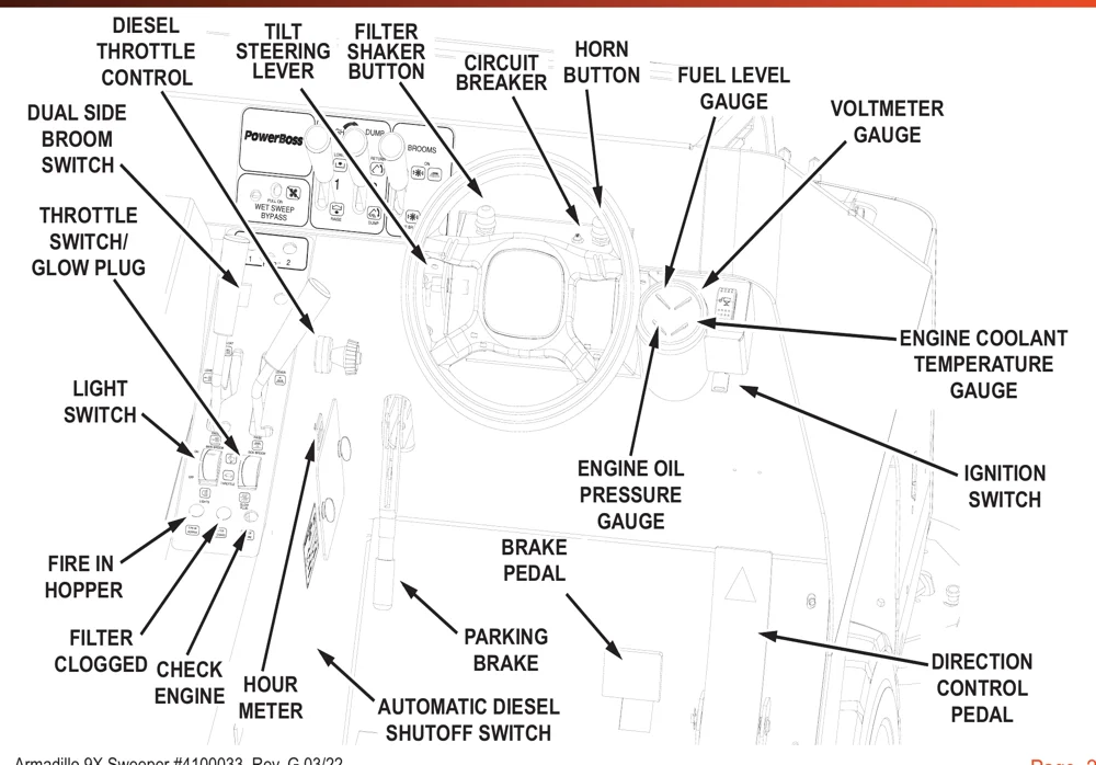
LIGHT SWITCH
The light switch, located in the lower left control panel area, turns the machine lights “On” and “Off”.
HOUR METER
The hour meter records the number of hours the machine has been operated with the key in the “On” position. This is a useful reference to help track routine maintenance tasks.
HORN BUTTON
The horn button is located behind the steering wheel. The horn will sound when the horn button is pressed and stop when the button is released.
AUTOMATIC DIESEL SHUTOFF SWITCH
Only on Diesel machines. This switch is for the automatic diesel shutdown that occurs if the oil pressure is too low.
HOPPER FILTER SHAKER BUTTON
The filter shaker button, located behind the steering wheel, is activated by pressing down and releasing the button. The filter shaker action is programmed to automatically run for 20 seconds. This action shakes debris off the hopper filter membrane. See page 31.
FUEL LEVEL GAUGE (DIESEL AND GAS ONLY)
The fuel gauge indicates the amount of fuel remaining in the fuel tank. Active on diesel and gas engines, only.
VOLTMETER GAUGE
The Voltmeter Gauge indicates the charging voltage (in Volts) from the alternator being sent to the battery. This gauge will indicate a drop in voltage when the alternator is not charging.
ENGINE OIL PRESSURE GAUGE
The engine oil pressure gauge ranges from 0 psi - 100 psi (0 kPa - 689 kPa). A reading below 7 psi (48 kPa) indicates problems which may result in damage to the engine.
ENGINE COOLANT TEMPERATURE GAUGE
The engine coolant temperature gauge ranges from 120°F - 250°F (48.9°C - 121.1°C). This gauge registers the temperature of the engine coolant. Temperatures above 220°F (104.4°C) indicate an overheating engine.
CIRCUIT BREAKER
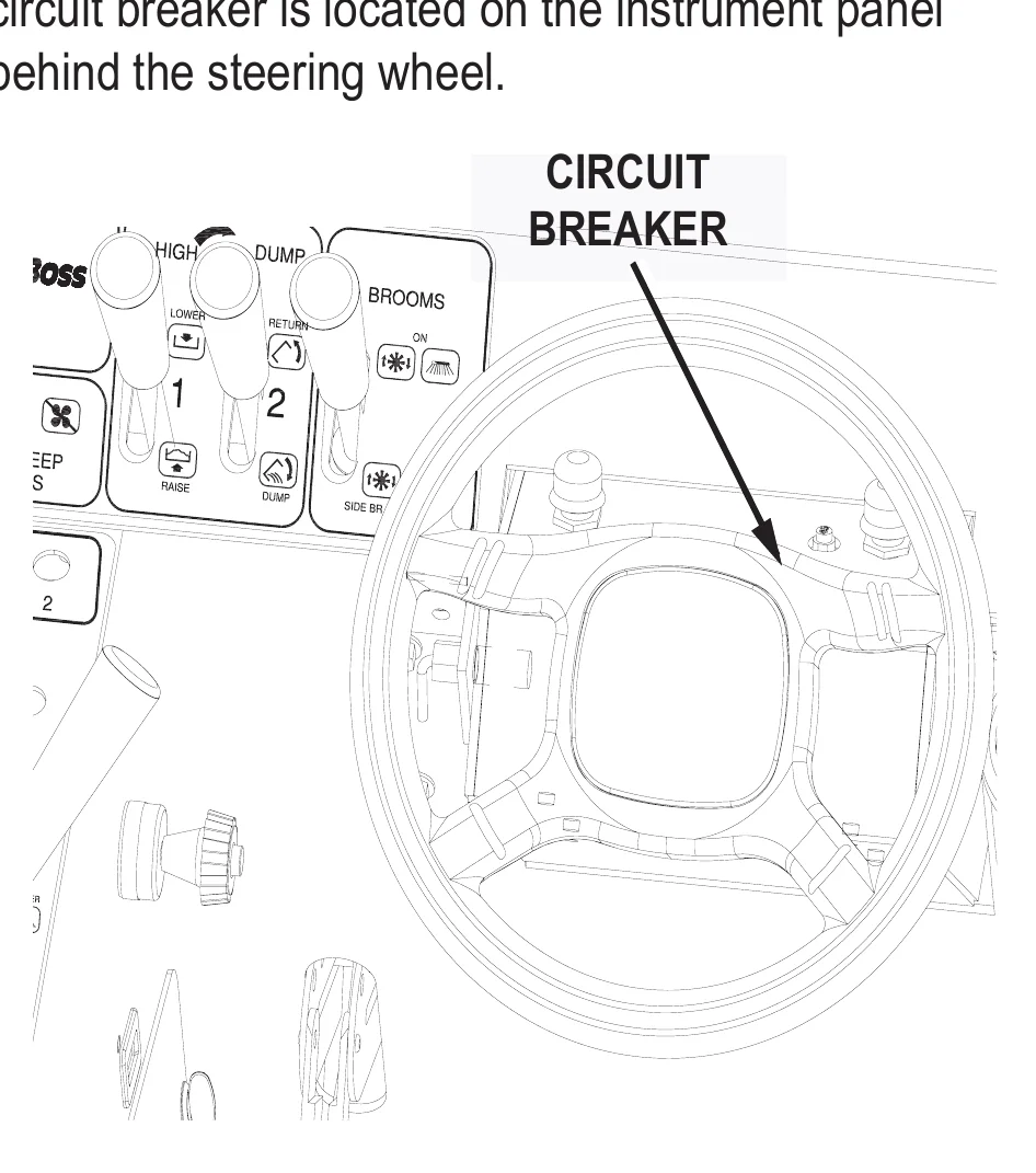
The Circuit Breaker is located behind the steering wheel. To reset the Circuit Breaker press the breaker button in until breaker stays in position.
DIRECTIONAL CONTROL PEDAL
The directional control pedal controls the speed and direction of the machine. It is also used for slowing the machine or stopping.
- To propel the machine forward, apply pressure to the front of the pedal, increasing pressure to increase speed.
- To propel the machine backward, apply pressure to the rear of the pedal.
- To slow or stop the machine, release pressure to the pedal. This is neutral position.
- For emergency stops, quickly move the foot pedal past neutral position in the opposite position.
The sweeper is equipped with a speed limiter. A stop is mounted under the directional control pedal and can be raised to reduce the maximum speed.
PARKING BRAKE
The Parking Brake is located on the left side of the front wall of the operator’s compartment. This brake manually engages the hydraulic drum brakes (operated by pressing on the brake pedal). To engage the Parking Brake, pull upward on the hand brake lever. To release the Parking Brake, push down on the hand brake lever.
BRAKE PEDAL
The hydraulic brake assembly is activated by pressing on the brake pedal. This action will activate the brakes being applied to both front wheels.
TILT STEERING LEVER
The steering wheel can be adjusted to provide the most comfortable position for the operator. To adjust, loosen the steering wheel by pulling up on the lever. Once loose, adjust the steering wheel up or down. To tighten wheel in position, push down on the lever.
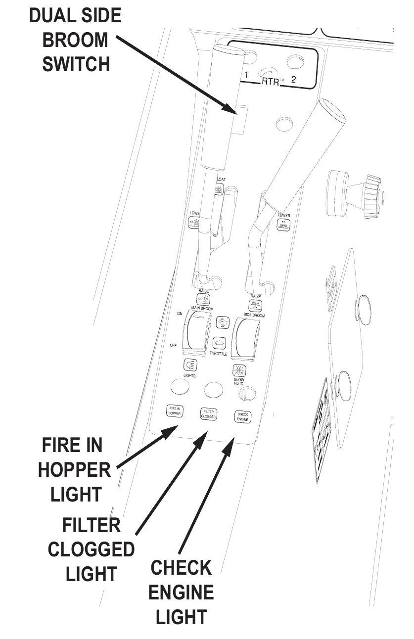
DUAL SIDE BROOM SWITCH
The dual side broom switch accompanies machines with the dual side broom option. This switch turns activates the dual side broom.
INDICATOR LIGHTS
FIRE IN THE HOPPER LIGHT
The fire in the hopper indicator will illuminate when a fire is detected in the hopper.
CLOGGED FILTER LIGHT
The clogged filter indicator will illuminate when it is necessary to clean or replace the filter element.
CHECK ENGINE LIGHT
The check engine light will illuminate if a problem is detected. The engine will be automatically shut off.
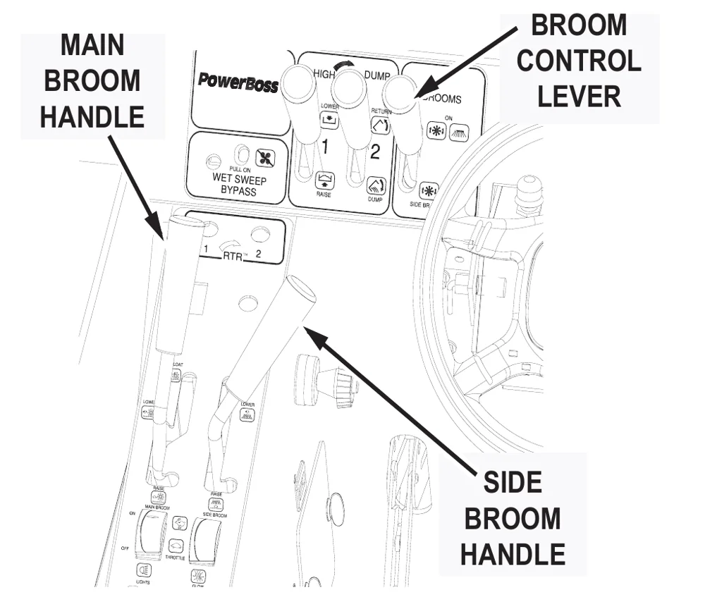
SWEEPING CONTROLS
BROOM CONTROL LEVER
The broom control lever activates the brooms. (“Side Broom OFF” position activates the main broom only.)
MAIN BROOM HANDLE
The main broom handle to the immediate left of the driver raises and lowers the main broom. For normal sweeping, position the handle at the LOWER position on the handle slot.
- For extremely uneven floor, position the handle at the FLOAT position on the handle slot.
- When not sweeping, position and lock the handle to the RAISE position on the handle slot.
SIDE BROOM HANDLE
The side broom handle to the immediate left of the driver raises and lowers the side broom.
- When not sweeping, the side broom should remain in the RAISE position.
- To lower the side broom, position the handle to the LOWER position in the handle slot.
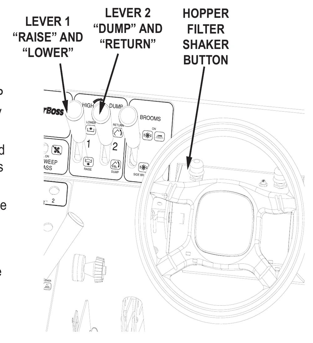
DEBRIS HOPPER DUMP CONTROLS
HOPPER FILTER SHAKER BUTTON
This button is used to activate the filter shakers prior to dumping or as needed during sweeping operation. It is located to the left hand side of the instrument panel.
To shake the filter:
- Bring the machine to a complete stop.
- Place the broom control lever in the OFF position.
- Press and release the filter shaker button, it will run automatically for 20 seconds.
- Place the broom control lever in the ON position and resume sweeping.
HIGH DUMP
The two far left levers on the front of the control panel are used to raise the hopper to any height up to 60 in (1,5 m) and dump it.
LEVER 1
Raises and lowers the hopper.
LEVER 2
Rotates hopper to dump debris, and returns (rotates back) the hopper to it’s starting position.
TO RAISE AND DUMP THE HOPPER:
- Pull back Lever 1 to the RAISE position until the hopper raises to the proper height for the dumpster or container.
- To empty debris, pull back Lever 2 to the DUMP position to rotate the hopper forward and empty the debris.
- To rotate the hopper back, push Lever 2 forward to the RETURN position until the hopper rotates and stops.
- To lower the hopper, push Lever 1 forward to the LOWER position until the hopper stops.
ROTARY TRASH RELOCATOR (RTR™)
Rotary Trash Relocator (RTR™) is a standard feature on high-dump models. It’s purpose is to increase the holding capacity of the debris hopper. This feature helps the operator manage debris and make less frequent debris dumping trips.
OPERATING PROCEDURES
PRE-OPERATION CHECKS
Prior to starting the engine, check the following:
- Engine oil level is within the operating range.
- Engine coolant level is within the operating range.
- Fuel level. For LP powered machines, confirm the LP tank is turnd on. To turn the valve ON, turn the valve counter clockwise until it stops. The valve is located on the LP tank.
- Hydraulic fluid level is within the operating range.
- Brakes, steering, and directional controls.
- Signs of fluid leaks on and under the machine.
Fluid levels should be within the correct amounts to opperate the machine.
Brakes, steering and directional controls should be functioning properly.
Hoses, lines and tanks should be free of damage and leaks.
STARTING
- Make sure the directional control pedal is in the neutral position.
- Make sure the throttle is in the idle position.
- LP and Gasoline-powered: Turn the ignition key to the start position (to the right). When the engine starts, release the button.
Diesel-powered: Turn the ignition key to the “on” position (do not try to start). Press down and hold the Glow Plug Switch for 10-12 seconds, release the switch. Turn the ignition key to the start position (clockwise). When the engine starts, release the key.
Move the machine forward or backward as follows:
- Forward: Apply pressure to the front of the directional control pedal, increasing pressure to increase speed.
- Reverse: Apply pressure to the rear of the pedal, increasing pressure to increase speed.
SLOWING AND STOPPING
Allow the directional control pedal to move into neutral. The machine will slow and coast to a stop.
OPERATING ON GRADES
- Always travel slowly.
- Exercise extreme caution when traveling across or turning on grades.
SWEEPING
- Lower the Brooms
- When sweeping extremely uneven floors, position the main broom handle at FLOAT on the handle slot.
- Lower the side broom by positioning the side broom handle at LOWER in the handle slot.
- Lower the main broom by positioning the main broom handle to LOWER on the handle slot.
- Activate the broom motors.
- Activate both main and side broom motors by pushing the broom and brush control lever to the ON position.
- Activate the main broom motor by pulling the broom and brush control lever to the SIDE BROOM OFF position.
- Drive the machine over the area to be swept.
EMPTY HOPPER WITH HIGH DUMP FEATURE
- Drive the machine to the dumping area.
- Use the directional control pedal to position the machine so that the space between the machine and the container or dumpster is adequate to raise the hopper.
- Reduce the engine speed.
- Pull back Lever 1 to the RAISE position and hold until the bottom of the hopper is high enough to clear the top of the container.
- Use the directional control pedal to slowly and carefully move the machine forward until the hopper is properly positioned to dump the debris into the container.
- Shake the filters for 20-30 seconds. Pull back Lever 2 to the DUMP position to rotate the hopper forward and empty the debris.
- After the hopper empties, push Lever 2 forward to the RETURN position until the hopper rotates and stops.
- Slowly back the machine away from the dumpster approximately 5 ft (1,5 m).
- Push Lever 1 forward to the LOWER position until the hopper stops.
ROTARY TRASH RELOCATOR (RTR™)
- Use the directional control pedal to stop the machine on a level surface.
- Move the throttle to the IDLE position.
- Light 1 illuminates when the hopper reaches the minimum height required to use the RTR™ feature.
- Light 2 illuminates to notify the operator that the hopper door is about to open to dump the trash.
- Pull back Lever 1 to the RAISE position and hold until Light 1 illuminates, then release.
- Pull back Lever 2 to the DUMP position and hold until Light 2 illuminates, then release.
- Push Lever 2 forward to the RETURN position until the hopper rotates back and stops.
- Push Lever 1 forward to the LOWER position until the hopper returns to the normal operating position.
- Move the throttle to the RUN position and resume sweeping.
TRANSPORTING THE MACHINE
Using a Trailer or Transport Vehicle
- Position the machine on the transport vehicle or trailer and apply the parking brake.
- Tie the machine down using the tie down holes in the frame forward of the front wheels and the hook bracket in the rear center of the frame.
Pushing the Machine
Push the machine from the front or rear using the bumpers only.
OPTIONS
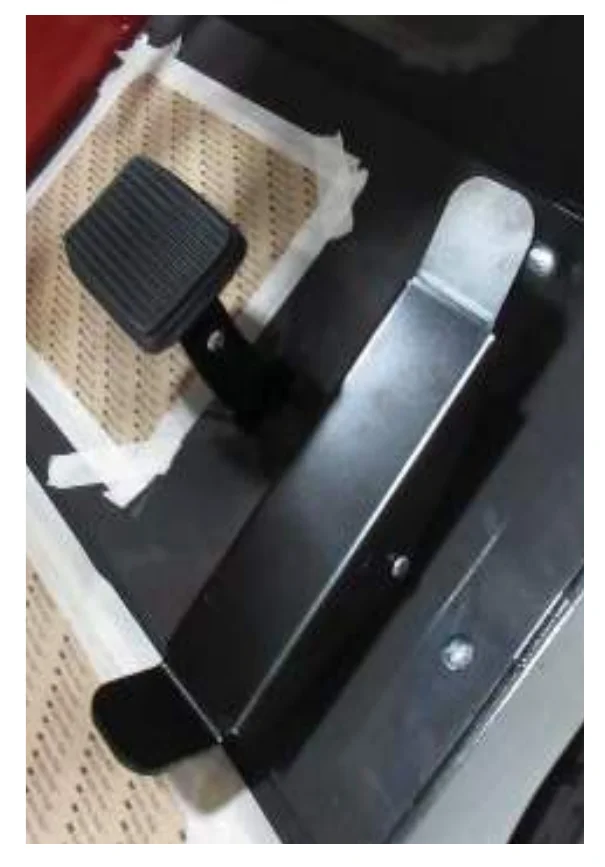
NEUTRAL START SENSOR
The Neutral Start Sensor safety option will not allow the engine to be started, if the Directional Control Pedal is pressed in the forward or backward position. The Pedal must remain in the neutral position to start the engine.
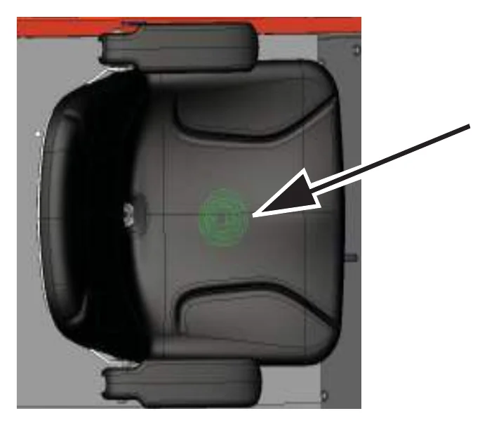
OPERATOR SEAT SENSOR
The Operator Seat Sensor safety option senses when the operator of the vehicle is sitting in the driver seat. This sensor will automatically turn off the running engine, if the operator leaves the seat for longer than 3 seconds. If the parking brake is engaged it will bypass the seat contact switch so that the machine will continue to run so the mechanic can work on it.
This safety option is standard on 9XCE machines and available for other 9X machines.
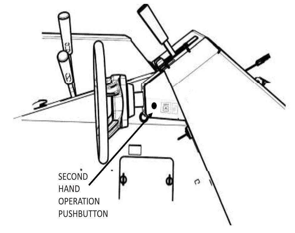
SECOND HAND OPERATION PUSHBUTTON
The second hand operation pushbutton is for operator safety when lowering the debris hopper. The operator must hold the yellow pushbutton on the side of the steering box. Once the pushbutton is held the operator may lower the hopper using the manual lever of the main spool valve. If the pushbutton is released at any point the hopper will stop lowering. The hopper may be lifted without holding the pushbutton as this is for lowering only.
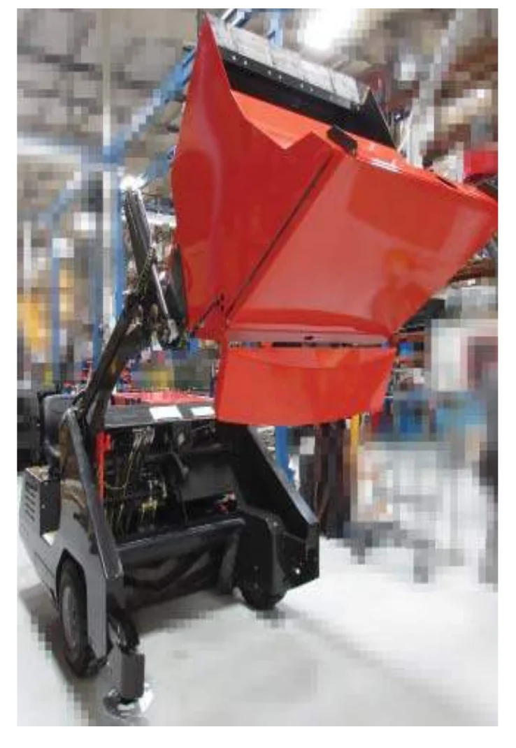
RAISE HOPPER - MAIN BROOM SHUT OFF
The Main Broom Shut Off (when hopper is raised) is a safety option that automatically shuts the main broom off, once the hopper is raised.
AUTOMATIC DIESEL SHUTOFF SWITCH
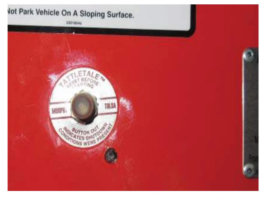
Only on the Diesel machines, this switch is an automatic diesel shutdown that occurs if the oil pressure is too low, below 5 psi (34 kPa), and/or the water temperature is too high, above 200°F (93.3°C). To start the engine, press and hold the switch while turning the ignition switch. This will action will reset and clear the error code. Auto shutdown will continue if the oil pressure remains low or the water temperature is to high.
LOW LP INDICATOR
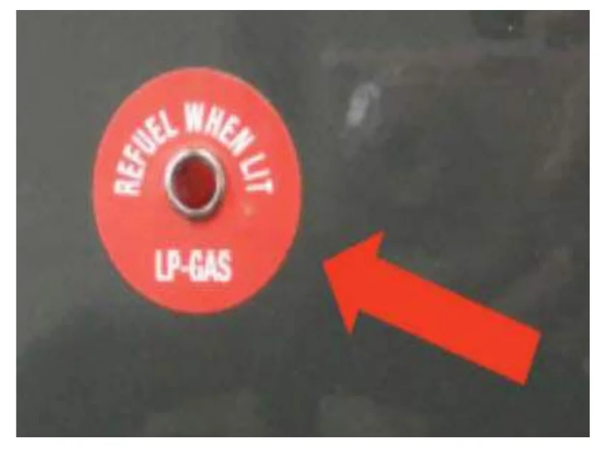
The low LP indicator is an option on machines powered by LP gas. The light is connected to a pressure valve mounted in the LP lines. When the pressure gets low in the LP tank (approximately 40 PSI) the indicator light will illuminate red. The indicator light is located on the operator dash area. When the light comes on the machine has approximately five minutes of running time left. The operator should go to the refueling station as soon as it is safely possible.
PARKING BRAKE BYPASS SWITCH
The parking brake bypass switch allows the machine to keep running when the operator gets off of a machine equipped with a seat switch and options requiring the operator to get off the machine to use. The parking brake must be engaged with the operator in the seat for this option to work. The operator is then able to use machine options that require being off of the machine (i.e. Blower wand, Vacuum wand). Engaging the parking brake keeps the machine from moving.
AIR CONDITIONING
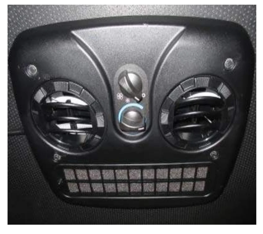
Air conditioning is available on units equipped with enclosed cabs. The air conditioning is mounted on the roof of the cab. The Air conditioning fan and temperature controls are mounted in the ceiling inside of the cab. The operator can control the direction of the air with integrated louvers in the blower outlets.
HEATER
The heater option is mounted in the seat frame near the back of the operator’s legs. The three speed blower control (plus off position) for the heater is located on the side wall of the operator console near the operators left leg. To turn off the heat when it will no longer be required for long periods of time, there is a shut off located on the engine. The shut off is a “T” valve that can be shut down to prevent hot coolant to circulate thru the heater.
CABIN PRESSURIZER
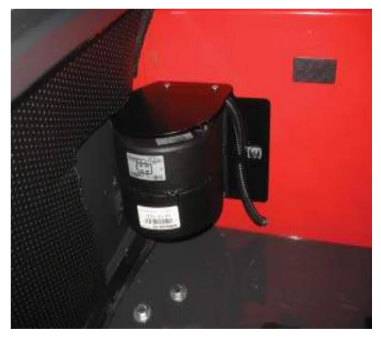
On units equipped with an enclosed cab, a Pressurizer is available. The Pressurizer mounts to the outside back of the cab and blows clean air in from behind the operator’s seat. The Pressurizer brings in outside air thru a removable filter mounted inside of its housing. The filtered air creates a positive pressure inside of the cab. This prevents dust from migrating into the cab as the machine is sweeping. There is a three speed blower control (plus off position) for the Pressurizer located on the operator console near the operators left leg. The Pressurizer filter should be cleaned or replaced every 50 hours or sooner depending on usage and environment.
VACUUM WAND
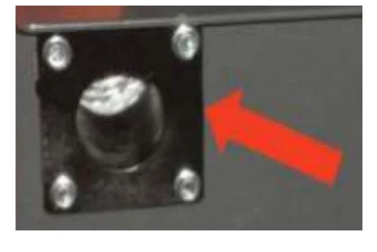
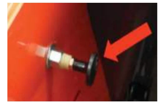
This option takes the vacuum being created for the normal sweeping operation and allows it to be used for vacuuming debris that the machine’s brooms can’t reach. To use this option remove the yellow port plug in the hopper access door, by loosening the “T” handle. Plug in the vacuum hose to the port in the hopper access door.
Make sure the main broom handle is all the way back and locked so that the main broom is not on the ground as this might cause damage to the broom or the floor it is operating on.
Put the brooms lever in the “Main Broom Only” position, which will turn on the vacuum impeller. Press the hopper door close rocker switch to the on position, this will create more vacuum by sealing the hopper opening.
Make sure the hopper door is back in the open position before sweeping with the machine again.
BLOWER WAND
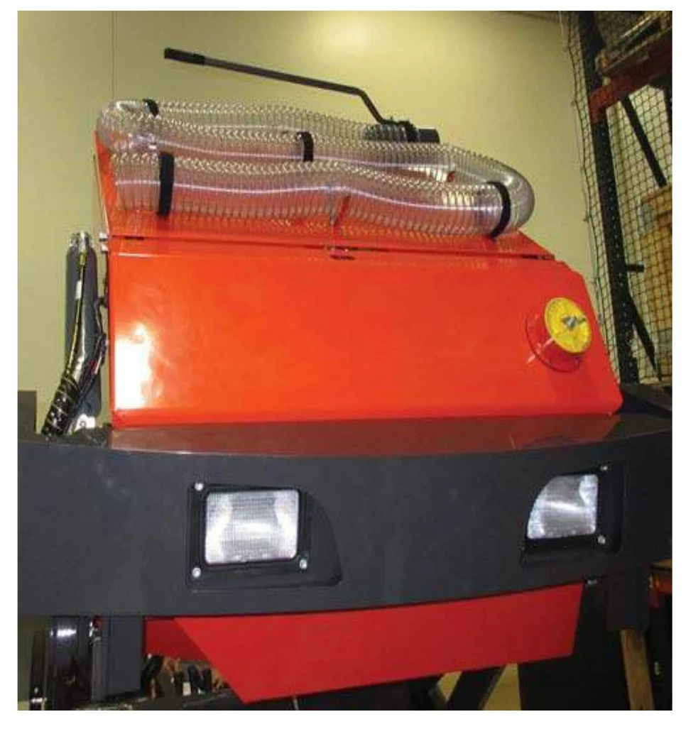
The blower wand option take the vacuum impeller exhaust air and diverts it to a port that comes out at the rear of the machine. There is a hose and wand attachment that connects to the port. Once the hose is placed over the end of the port, the diverter cable may now be moved into the bypass position. The impeller exhaust air will now flow out of the hose and wand for moving debris that can’t be reached by the machine brooms. For this option to operate the machine must have the vacuum impeller operating at full engine RPM. The machine parking brake must be engaged, which activates the seat switch bypass switch so the operator may get of the machine and use the blower wand.
DUAL CURB BROOM
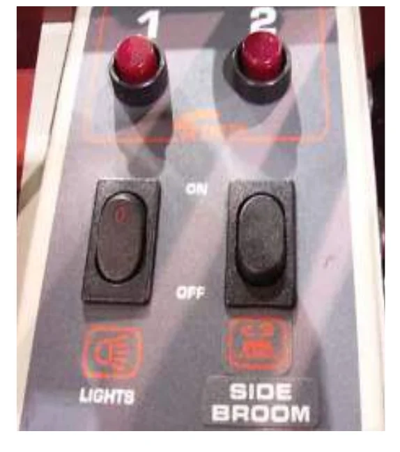
The dual curb broom option adds a second side broom to the left front of the machine. The left side broom is activated by the left side broom rocker switch. When the switch is moved to the on position the left side broom is lowered by an actuator to the operating position. The brooms lever must be in the side brooms position for both side brooms to rotate. The side brooms may be lowered independently of each other but both brooms will turn when the brooms lever is move into the side brooms position.
DUST SUPPRESSION SYSTEM
The dust suppression system limits the amount of dust in the air around the machine while operating and aids in the sweeping process. The system has an air compressor, water tank and spray nozzle as the main components of the system. The water tank should be filled before operating the system and checked periodically during operation to make sure there is water for the spray nozzle. The system is controlled by the dust suppression system rocker switch. When this switch is moved to the on position the compressor will start and continue to run. There are two solenoids with the system one for the water and one for the compressed air. Both solenoids also turn on when the rocker switch is pressed on, which allows the air and water to come out of the spray nozzle in a fine mist pattern in front of the side broom. The spray nozzle is set at the factory so no adjustment should be necessary.
SEAT BELTS
Seat belts are offered as an option on both the standard seat, and the suspension seat.
LIGHTS
Safety lights are offered in blue, amber, or red. The lights can be mounted on the solution tank, the engine cover, or the Overhead Guard. The lights can flash, rotate, or strobe.
The lights will come on automatically when the machine is turned on.
SUSPENSION SEAT
The suspension seat comes equipped with:
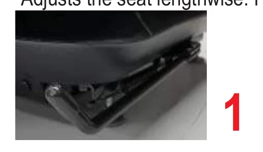
- Hand lever for seat adjustment.
Adjusts the seat lengthwise. Pull lever to release. Let the lever catch after adjustment.
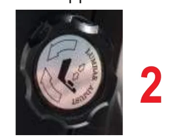
- Rotary knob for lumbar adjustment.
Turn knob to the left for more support. Turn the knob to the right for less support.
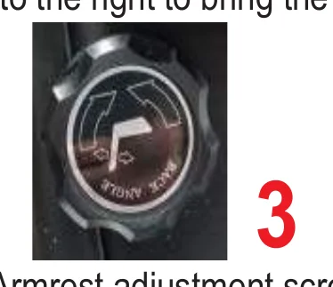
- Rotary knob for backrest adjustment.
Turn knob to the left to incline the seat backward. Turn the knob to the right to bring the seat back up.
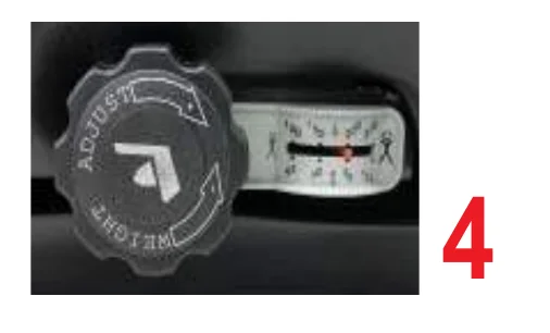
- Rotary knob for cushion adjustment.
Turn knob to the right for firmer cushion support. Turn knob to the left for softer cushion support.
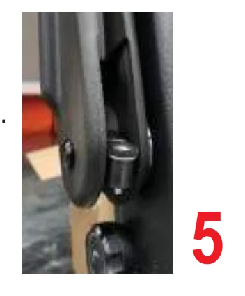
- Armrest adjustment screw.
Adjusts the inclination of the armrest.
PREVENTATIVE MAINTENANCE
INTRODUCTION
Regular maintenance on your sweeper results in better cleaning, faster cleaning and a prolonged service life for the equipment and components. This section contains the following information to help you give your sweeper the maintenance attention it requires:
- A Scheduled Maintenance Chart
- Preventative Maintenance Instructions for Required Scheduled Maintenance Tasks
Because it is extremely important to your safety, you will see the following WARNING repeated throughout this section:
SCHEDULED MAINTENANCE CHART
| FREQUENCY (IN HOURS) | SERVICE (BY MAINTENANCE AREA) | ||||
|---|---|---|---|---|---|
| DAILY | 50 | 100 | 200 | 500 | |
| ENGINE | |||||
| X | Pressure wash engine NOTE: For additional maintenance requirements, refer to the engine manual. | ||||
| AIR INTAKE SYSTEM | |||||
| X | Empty rubber dust cup of air filter element. | ||||
| X | Check air filter indicator | ||||
| X | Clean air filter. NOTE: Clean more often in dusty conditions. | ||||
| X | Replace air filter. | ||||
| ELECTRICAL SYSTEM | |||||
| X | Clean battery top. | ||||
| COOLANT SYSTEM | |||||
| X | Check coolant level and fill as needed. | ||||
| X | Inspect radiator fins and clean as needed. | ||||
| X | Blow out radiator fins. | ||||
| X | Drain and flush the coolant system | ||||
SCHEDULED MAINTENANCE CHART
| FREQUENCY (IN HOURS) | SERVICE (BY MAINTENANCE AREA) | ||||
|---|---|---|---|---|---|
| DAILY | 50 | 100 | 200 | 500 | |
| LUBRICATION POINTS | |||||
| X | Steering Cylinder (2 fittings) Lubricate type - grease (Do not Pressure Steering Cylinder) | ||||
| X | Engine Mount Pivot (1 fitting) Lubricate type - grease | ||||
| X | Hood Latches & Hinges Lubricate type - oil | ||||
| X | Hopper Lift Arm Mounts (2 fittings on each mount) Lubricate type - lithium grease | ||||
| IMPELLER | |||||
| X | Check for hydraulic fluid leaks. | ||||
| HYDRAULIC SYSTEM | |||||
| X | Check hydraulic reservoir gauge and fill as needed. | ||||
| X | Replace breather cap filter element. | ||||
| X | Replace hydraulic fluid and filter | ||||
| X | Check functioning of directional control pedal and adjust as needed. | ||||
| X | Clean hydraulic fluid strainer in reservoir. | ||||
| X | Inspect hydraulic oil cooler fins and clean as needed (if so equipped). | ||||
| X | Blow out hydraulic oil cooler fins with compressed air (if so equipped). | ||||
SCHEDULED MAINTENANCE CHART
| FREQUENCY (IN HOURS) | SERVICE (BY MAINTENANCE AREA) | ||||
|---|---|---|---|---|---|
| DAILY | 50 | 100 | 200 | 500 | |
| SWEEPING COMPONENTS | |||||
| X | Inspect brooms for wear and remove strings and debris from bristles and drive assembly. | ||||
| X | Inspect broom skirts for wear and adjust or replace as needed. | ||||
| X | Rotate main broom end-to-end. | ||||
| X | Perform main broom adjustment test and adjust as needed. | ||||
| X | Inspect the side broom for wear and adjust as needed. | ||||
| Replace main and side brooms as needed: Main Broom needs to be replace if bristles are 1 in (2,5 cm) in length or less. Side Broom needs to be replaced if bristles are 3 in (7,6 cm) in length. | |||||
| HOPPER | |||||
| X | Check hopper filters and clean or replace as needed. | ||||
| X | Check hopper clearance from floor and adjust as needed. | ||||
| X | Inspect the hopper flaps for wear or damage and replace as needed. | ||||
| X | Inspect hopper side and frame seals for wear or damage. Adjust or replace as needed. | ||||
SCHEDULED MAINTENANCE CHART
| DAILY | 50 | 100 | 200 | 500 | SERVICE (BY MAINTENANCE AREA) |
|---|---|---|---|---|---|
| STEERING | |||||
| X | Check for leaks. | ||||
| PARKING BRAKE | |||||
| X | Check for proper functioning and adjust as needed. | ||||
| WHEELS AND TIRES | |||||
| X | Visually inspect for wear and damage. Repair or replace as needed. | ||||
| X | Check pneumatic tires for proper air pressure 95 psi (655 kPa) | ||||
| X | Check and tighten lug nuts torque to 100 lb·ft (135 N·m) | ||||
| MISCELLANEOUS | |||||
| X | Inspect latches and hinges. Tighten and lubricate as needed. | ||||
| X | Check anti-static drag chain on rear wall of broom chamber for damage or excessive wear. Replace as needed. | ||||
| X | Check side broom lift cable and lift cable for wear. | ||||
PREVENTATIVE MAINTENANCE INSTRUCTIONS
ENGINE
Maintenance requirements and service instructions for your sweeper engine are outlined in the following parts of this Maintenance Section:
- Air Intake System
- Electrical System
- Fuel System
- Coolant System
- Lubrication System
All basic maintenance tasks are listed with their recommended frequencies on the Planned Maintenance Chart in this manual. Important additional maintenance requirements and instructions are explained in the engine manual which comes with your machine.
AIR INTAKE SYSTEM
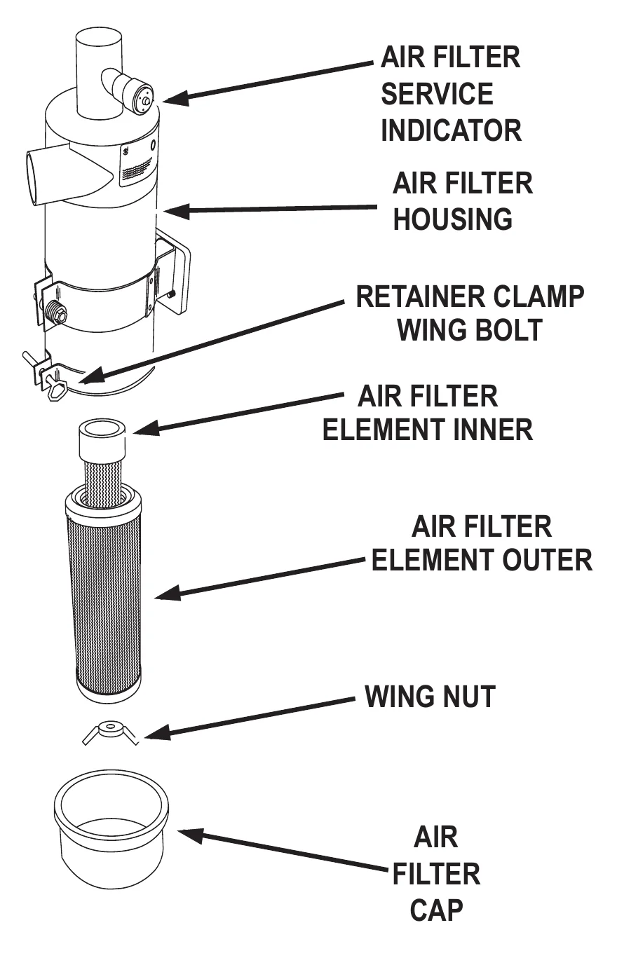
Check Air Filter Service Indicator
The air filter service indicator shows when to change the air filter element. Check the indicator on a daily basis. The red indicator gradually becomes visible as the air filter elements load with dirt. It is not necessary to change the air filter elements until the red indicator reaches the top of the service indicator and locks into position.
- Lift engine cover.
- Inspect air filter service indicator.
Air Filter Element Removal
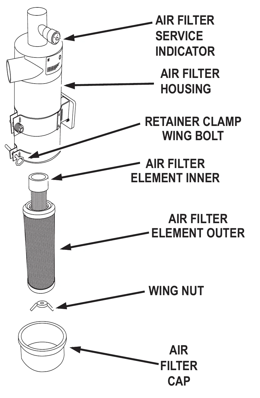
- Turn off the engine and set the parking brake.
- Lift the engine cover.
- Locate the air filter.
- Loosen the retainer clamp wing bolt.
- Remove the air filter cap, shake out loose debris.
- Remove wing nut holding outer air filter element. Remove outer air filter element from housing.
- Remove wing nut holding inner air filter element. Remove inner air filter from housing.
Air Filter Cleaning
- Once you have removed the air filter elements, clean the air filter cap and clean the interior of the air filter housing.
- Use an air hose to blow out the air filter elements. Air pressure should be 100 psi (689 kPa) or less.
Air Filter Inspection
- After you clean the air filter elements, inspect the filter element for holes and damage. If a filter element is damaged, replace with a new filter element.
Air Filter Installation
- Wipe out the air cleaner housing with a damp cloth. Be sure all dirt is removed.
- Insert the cleaned inner air filter element, secure and tighten in place with the wing nut.
- Insert the cleaned outer air filter element, secure and tighten in place with the wing nut. Note: Insert the filter end with the fins first, be careful not to damage the fins.
- Place the air filter cap back on to the air filter housing, secure and tighten retainer clamp with the wing bolt.
- Check the condition of intake hoses and clamps.
- Close engine cover.
ELECTRICAL SYSTEM
Battery Cleaning
- Combine baking soda and water in a strong solution.
- Brush the solution over the battery top, including terminals and cable clamps. Make sure the solution does not enter the battery.
- Using a wire brush, clean the terminal posts and cable clamps.
- Apply a thin coating of petroleum jelly to the terminals and cable clamps.
Battery Replacement
- Disconnect the negative (-) cable and then the positive (+) cable.
- Remove the battery.
- Install the new battery.
- Connect the positive (+) battery cable first, then the negative (-) cable.
Circuit Breaker
If the circuit breaker trips, it can be reset by pressing the reset button in the center of the breaker. The circuit breaker is located on the instrument panel behind the steering wheel.
Fuses
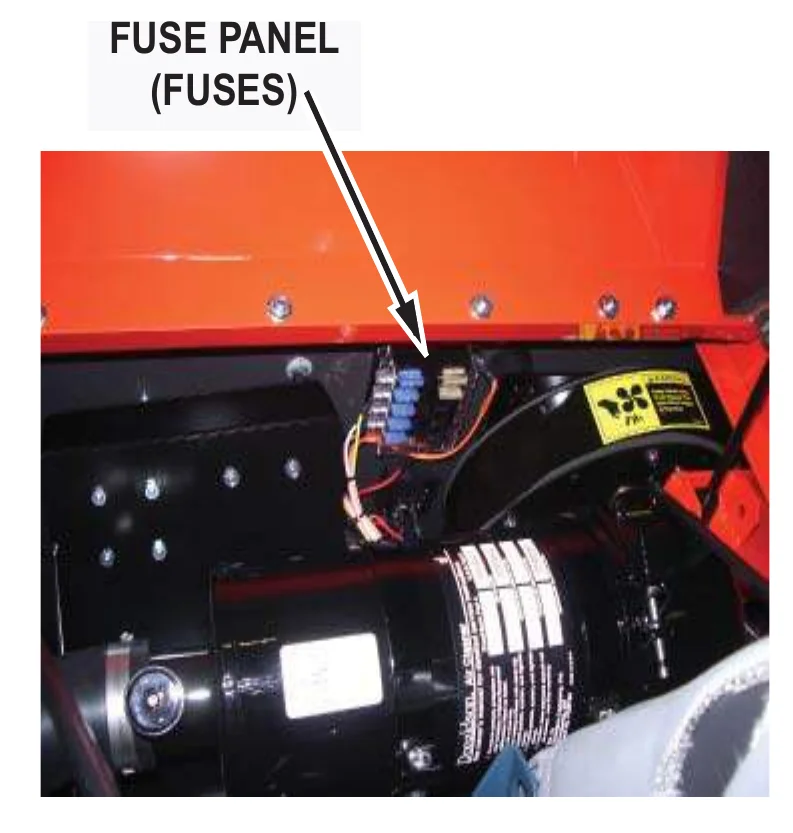
Fuses are located in the fuse panel under the engine hood on the fire wall near the vacuum fan inlet.
FUEL SYSTEM
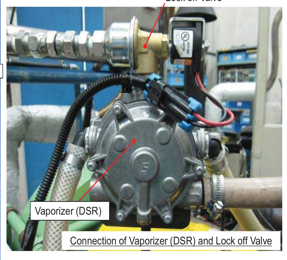
LPG Fuel System
Lock off Valve
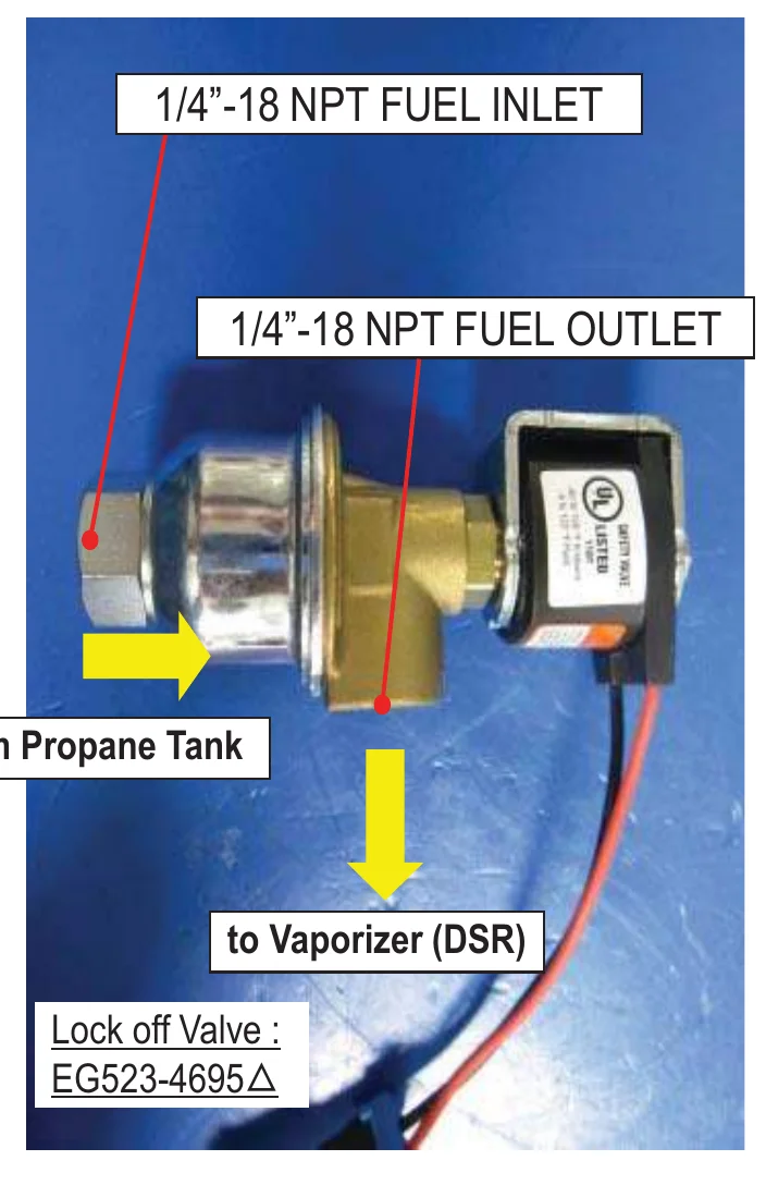
Lock off Valve : EG523-4695△
COOLANT SYSTEM
Blowing Out Radiator Fins
Reverse Flow Flushing
- At the engine, disconnect the hoses.
- Make sure the radiator cap is on tight.
- Using a hose clamp, attach a flushing gun onto the lower hose.
- Turn on the water and fill the radiator.
- To keep from damaging the radiator, apply air pressure slowly and carefully.
- Shut off the air pressure, refill the radiator with water, and reapply the air pressure. You will need to repeat these steps until water flushed from the radiator runs out clear.
- Inspect and clean the radiator cap.
- Inspect and reconnect the hoses.
- Refill the radiator with coolant.
LUBRICATION
For all engine fuel types: Use a current API (American Petroleum Institute) Oil Service Classification that is suited to seasonal temperatures.
Refer to the Engine Manufacturer’s Operator Manual for these specifications.
Changing Engine Oil
- Place a drain pan under the lowest end of the engine.
- Remove the drain plug and allow the oil to drain into the pan.
- Remove the used oil filter and replace with a new one.
- Dispose of the oil and oil filter in an approved manner.
- Remove the engine oil cap, add oil in the amounts listed in the engine manual, then secure the cap.
LUBRICATION POINTS
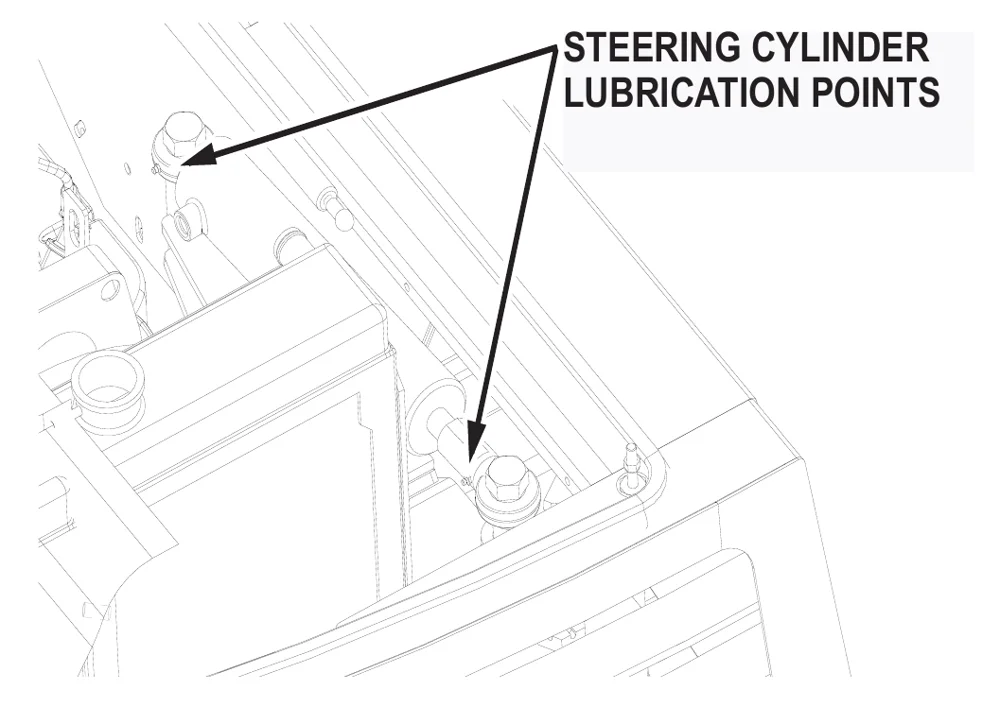
Steering Cylinder
The steering cylinder must be lubricated every 50 hours with grease. There are two grease points on the cylinder.
Engine Mount Pivot
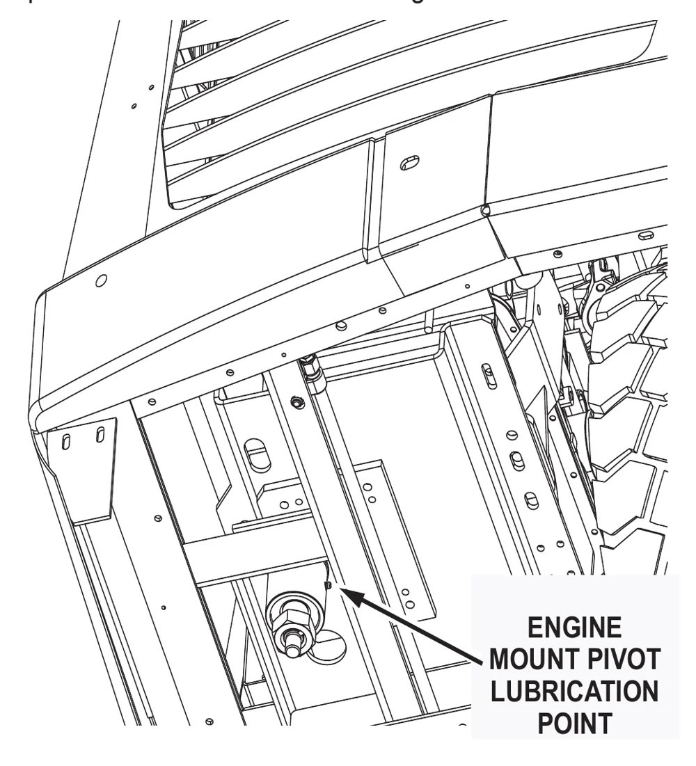
The engine mount pivot must be lubricated every 500 hours with grease, There is one lubrication point on the pivot located underneath the engine.
Latches & Hinges
The hinges and latches and all doors and covers should be lubricated with oil every 500 hours. There are numerous hinges and latches, make sure to lubricate all of the following:
- Engine cover
- Side Door
- Main Broom Door
- Seat Hinge
- Engine latch
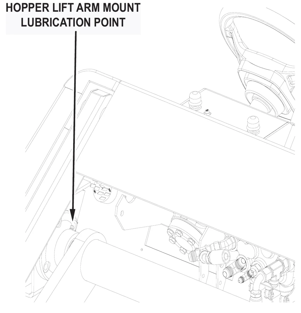
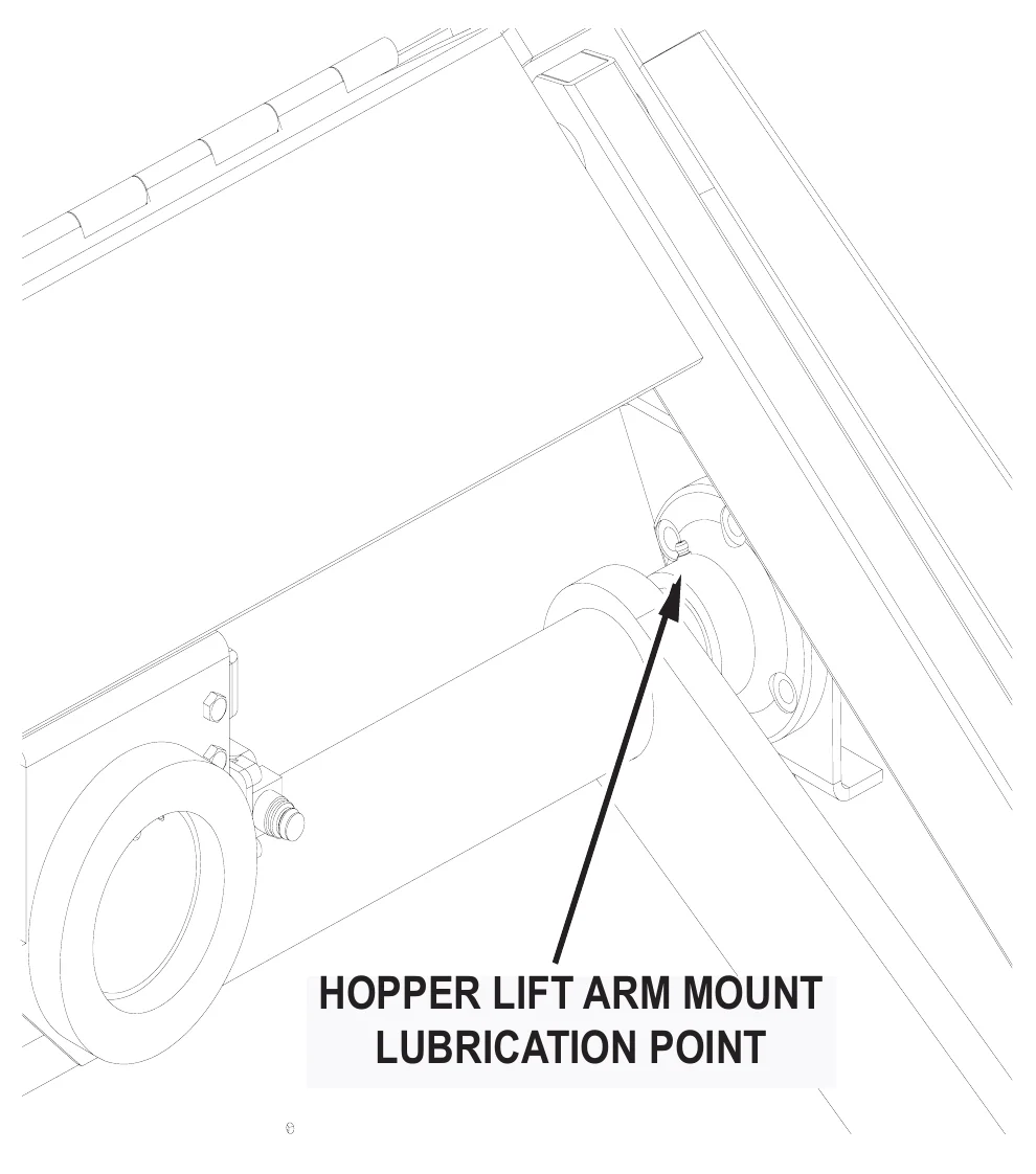
Hopper Lift Arm Mounts
The hopper lift arm mounts must be lubricated every 500 hours with lithium grease, There are two lubrication point on each mount.
- Park the machine on a level surface.
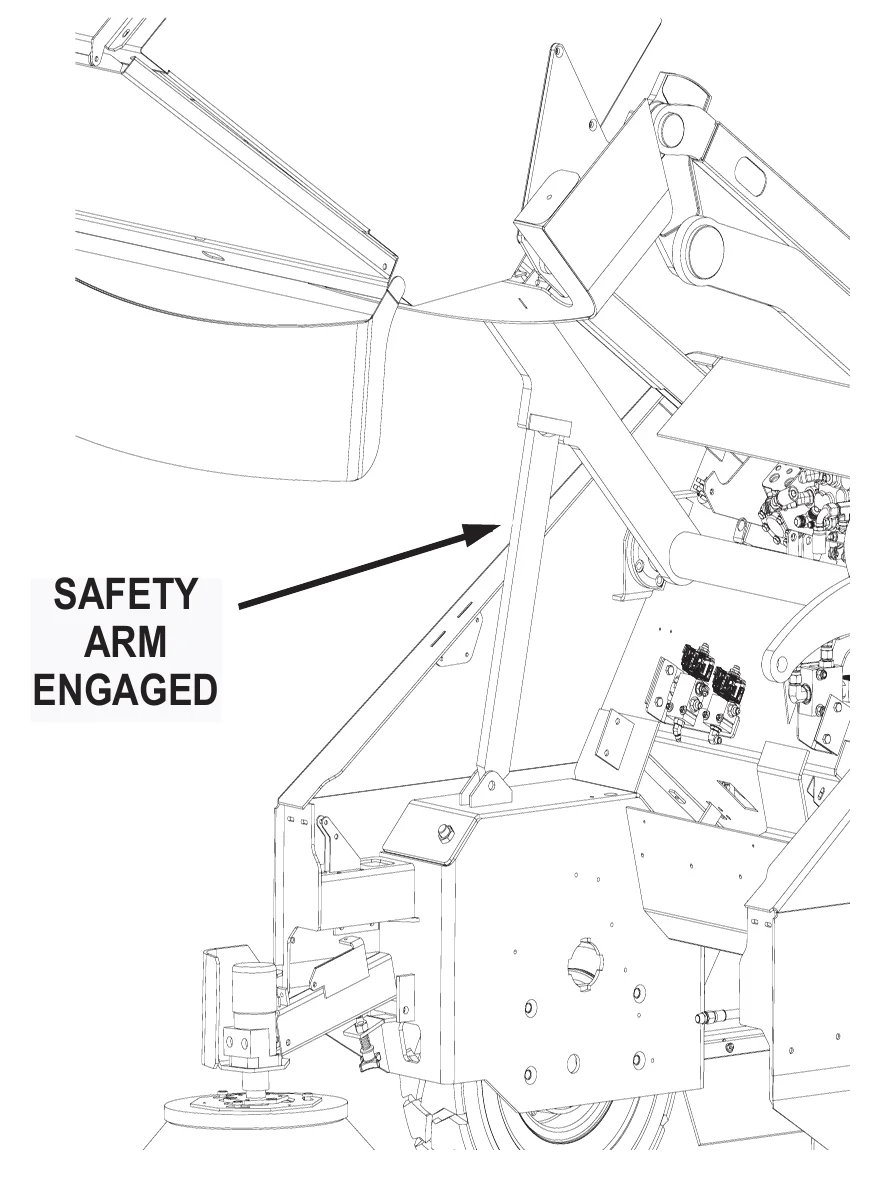
- Raise the hopper and engage the safety arm
- Shut off the engine and engage the parking brake.
- Locate and grease the hopper lift arm lubrication points.
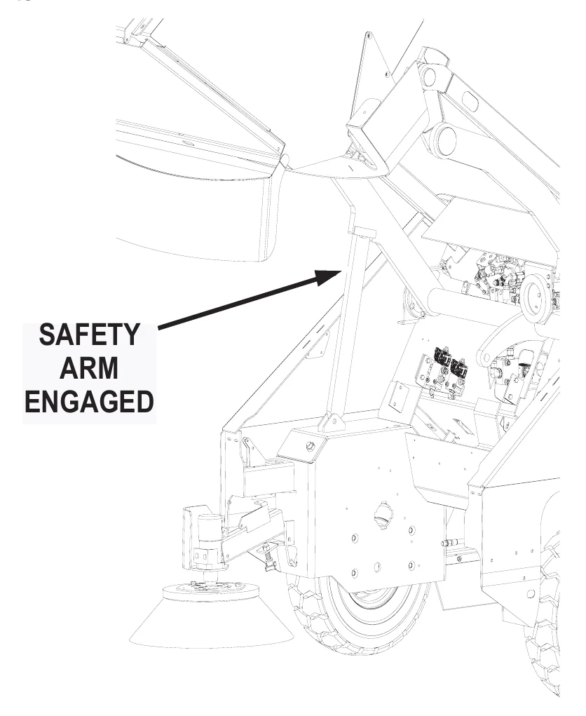
Hopper lift arm mount lubrication point
HYDRAULICS SYSTEM
Filling The Fluid Reservoir
- When the machine is cool and the hopper is in the lowered position, remove the dipstick. Fluid level should be between the high and low marks on the dipstick.
- If the fluid level is not acceptable, add hydraulic fluid.
Hydraulic Fluid Viscosity Specifications
Mobil DTE 10 Excel 32 - Viscosity, ASTM D445
cSt @ 40°C (104°F): 32.7
cSt @ 100°C (212°F): 6.63
Maintaining Hydraulic Oil Cooler Efficiency
Your machine is equipped with a hydraulic oil cooler, it is integrated with the radiator and utilizes exhausted radiator air from the engine fan to cool the hydraulic fluid. To maintain its efficiency, periodically blow out the radiator & oil cooler fins with compressed air - 100 psi (689 kPa) maximum.
Changing The Hydraulic Fluid
- Turn off the engine and engage the parking brake.
- Place a drain pan on the floor below the reservoir.
- Remove the drain plug located on the bottom rear of the reservoir and allow the fluid to drain.
- Discard the fluid in an approved manner, then replace and retighten the drain plug.
- Remove the filler / breather cap located on top of the reservoir and fill the reservoir with approved hydraulic fluid.
- Install the filler cap assembly.
- Check the drain plug for leakage.
Changing The Hydraulic Fluid Filter
- Turn off the engine and engage the parking brake.
- Unscrew the oil filter cartridge from the mount and discard in an approved manner.
- Apply a thin coating of fluid to the seal of a new filter element.
- Thread onto the mount and hand tighten.
- Tighten an additional one-half turn beyond hand tight.
- Start the machine, shut it off, then check for leakage.
Adjusting The Directional Control Return Spring
You may encounter “creeping” problems from time to time. Creeping means the machine moves backward or forward when the forward/reverse pedal is in neutral. A grinding noise when the engine is shut down is also an indicator that the directional control return spring needs adjusting. If this occurs, perform the procedure which follows:
- Turn off the engine, engage the parking brake and chock both wheels.
- Jack the rear of the machine so that the rear tire just clears the floor. Use two jack stands to support the machine.
- Locate the forward / reverse adjustment bracket mounted beneath the pump on the pump mounting plate.
- Slightly loosen the bolt on the center of the bracket.
- Loosen the locking nut on each of the adjusting bolts on the side of the bracket closest to the pump mounting plate.
- From the operator’s seat, start the engine and run at half throttle.
- Turn the adjusting bolts while watching the rear wheel. Continue to adjust until the rear wheel does not turn in either direction.
- Fully open the throttle. Push the directional control pedal forward and backward to be sure the pump stays in neutral. Check the wheel again and adjust as needed until the wheel remains motionless.
- Retighten all the locking nuts and bolts.
- Turn the engine off and lower the machine to the floor.
SWEEP COMPONENTS
Broom Door Flap Inspection
- Turn the machine off and lock the parking brake.
- Inspect broom door flaps for wear and damage. Flap clearance should be 0.125 in (0,3 cm) above the floor.
- Worn and damaged flaps should be replaced immediately to maintain proper dust control.
Broom Door Flap Replacement and Adjustment
The flaps are attached to the broom doors by a retainer bar, hex bolts and nuts. To remove the flaps, remove the nuts, bolts and retainer bar. To adjust the flaps, loosen the nuts and bolts, slide the flap up or down as needed. Retighten the nuts and bolts.
Main Broom Adjustment
- Drive the machine onto the test surface with the main broom in the RAISE position.
- Set the parking brake and position the main broom to the NORMAL position.
- Push the broom control switch to the ON position to activate the broom motor and open the throttle to full RPM.
- Allow about 45 seconds for the broom to operate, then deactivate the broom motor and raise the broom.
- Drive the machine clear of the test site.
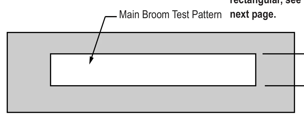
- Examine the polished pattern made by the broom on the test area.
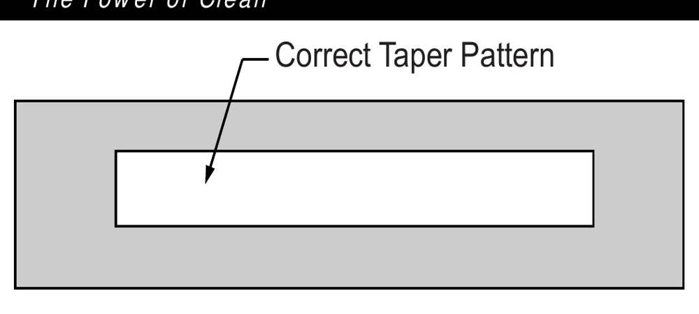
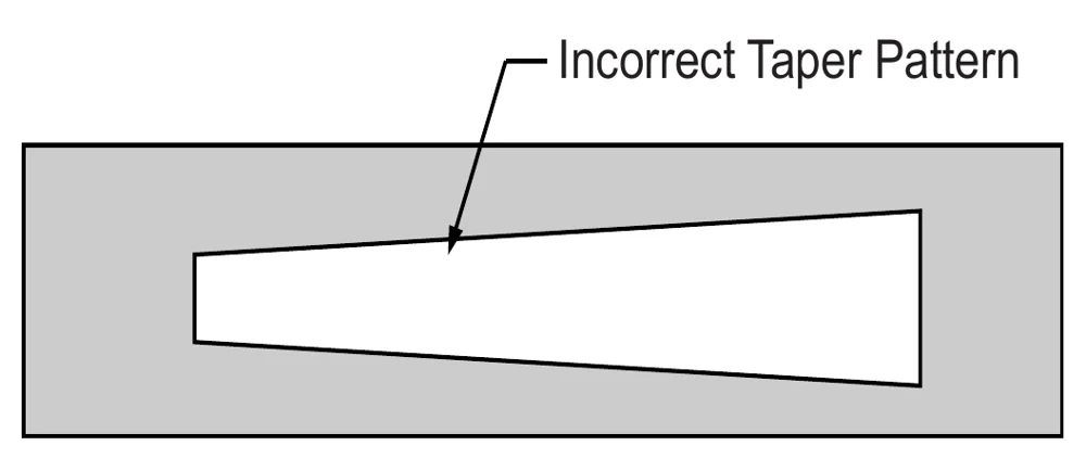
A pattern smaller then 2 in (5,08 cm) indicates need for lower adjustment. A pattern wider than 2 in (5,08 cm) indicates a need for higher adjustment. If pattern is tapered from end to end instead of rectangular, see Taper Adjustment on the next page.
Main Broom Height Adjustment
- Turn the machine off and lock the parking brake.
- Position the main broom lever in the LOWER position.
- Turn the broom adjusting knob clockwise one-eighth turn to free the wing nut.
- Turn the wing nut counter-clockwise to allow space for adjustment.
- Make a lower or higher adjustment with the knob as required.
- Retighten the wing nut.
- Repeat the main broom adjustment test to see that the broom is properly adjusted.
Main Broom Taper Adjustment
- Locate the adjusting screws directly beneath the hydraulic pump.
- Loosen the jam nuts on the adjusting screws, and loosen the retaining bolt on the inside of the mounting bracket.
- Use the adjusting screws to raise or lower the left end of the main broom. (The right end of the broom remains fixed. All adjustments affect the left end of the broom.)
- After adjustment, tighten the retainer bolt and adjusting screws.
- Repeat the main broom adjustment test to see that the broom is properly adjusted.
Main Broom Replacement
- Turn the engine off and lock the parking brake.
- Push the main broom control lever to the LOWER position
- Open the left broom chamber door (the door opposite the driver’s seat).
- Using a ¾ in (19 mm) wrench, remove the hex bolt on the main broom idler mount.
- Pull the main broom idler mount straight out to remove.
- Grasp the main broom by the plastic drive hub, pull the main broom straight out and clear of the broom chamber.
- Depending on broom condition, you can either rotate the old broom end-to-end and re-install it or you can install a new broom. Slide the main broom into the broom chamber and align the broom with the metal drive hub located at the far side of the broom chamber.
If a worn broom is being replaced, install the new broom by first adjusting the broom arms up, to better match the position of the drive hub with the hub on the new broom.
- Once the broom is started onto the drive hubs, rotate the broom counter-clockwise while pushing lightly against the broom.
- Once the broom is fully engaged, replace the idler hub while aligning the seats in the idler hub with the broom’s drive hub ears.
- Install the retaining bolt into position and tighten with the wrench.
- Close and latch the left broom door.
- Perform a main broom adjustment test and adjust as needed.
Side Broom Angle Adjustment
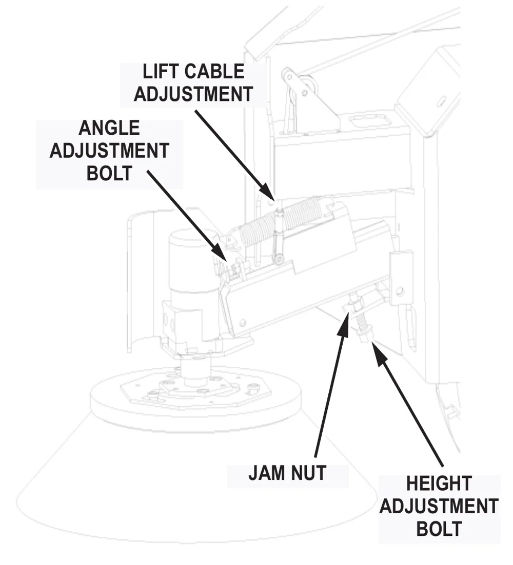
The angle adjustment is controlled with a stop bolt. This stop bolt is located at the top front of the side broom arm (under the spring). To increase the angle of the side broom, loosen the jam nut and turn the stop bolt counter-clockwise. Be sure to retighten the jam nut back down once the adjustment is made.
Side Broom Height (Wear) Adjustment
The height of the side broom is adjusted with the use of a stop bolt located at the lower rear of the curb broom arm. As the side broom wears, it will be necessary to lower the arm.
Adjust Side Broom Height
To lower the side broom, loosen the jam nut on the stop bolt. Turn the stop bolt in a counter-clockwise direction, check the side broom for proper contact and re-tighten the jam nut.
Side Broom Lift Cable Adjustment
This adjustment is made at the cable clevis attached to the side broom assembly. It controls the height of the side broom in the RAISED position. This adjustment must be made with the hopper fully lowered.
- Pull the side broom lever into the RAISED position.
- Loosen the locknut on the threaded rod at the clevis.
- Turn the threaded rod in or out to set the side broom in the maximum raised position.
- Secure the cable adjustment by tightening the locknut.
Side Broom Replacement
- Raise the side broom and lock in the RAISE position.
- Turn the side broom by hand until the brush retainer bar is accessible.
- Lift the bar and turn the broom clockwise (about one eighth of a turn) until the lock pins in the broom disengage from the drive plate.
- Install the new broom by positioning the three drive pins into the pilot holes of the drive plate.
- Lift and rotate the broom until the broom retainer bar springs into the locked position.
- Check to make sure all three drive pins are properly engaged.
HOPPER
High Dump Hopper Removal
- Park the machine on a level surface and engage the parking brake.
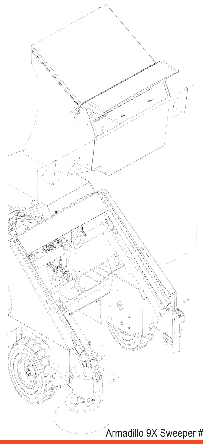
- Raise the hopper and position the high dump hopper dolly, a platform truck or similar four wheeled cart under the hopper.
- Set the hopper down on the truck and turn the engine off.
- Cycle the rotation control handle (#2) in both positions to relieve any residual hydraulic pressure.
- Remove three bolts, washers, nuts and backing plate.
- Disconnect the wire harness connections at the right side of the hopper.
- While spreading the dump arms slightly, roll the hopper away from the machine.
High Dump Hopper Replacement
- Position the hopper on the dolly so as to align the mounting holes in the sides of the hopper with the rotation mounts on the arms. Lift arms should be positioned about ⅓ of the way up.
- Engage the lift arm rotation plates with the mounting bolts on each side of the hopper.
- Start the machine and lift the hopper.
- Drive away from the hopper dolly or cart.
- Lower the hopper.
- Engage the wire connections at the right side of the hopper.
Floor Clearance and Dump Angle Adjustment
- Park the machine on a level surface, shut off the engine and engage the parking brake.
- Adjust the lift arm stop bolts located on top of the wheel wells as low as possible while still allowing the side broom assembly to clear the lift arms when the hopper is in the NORMAL position. Be sure that both lift arms contact the stop bolts at the same time.
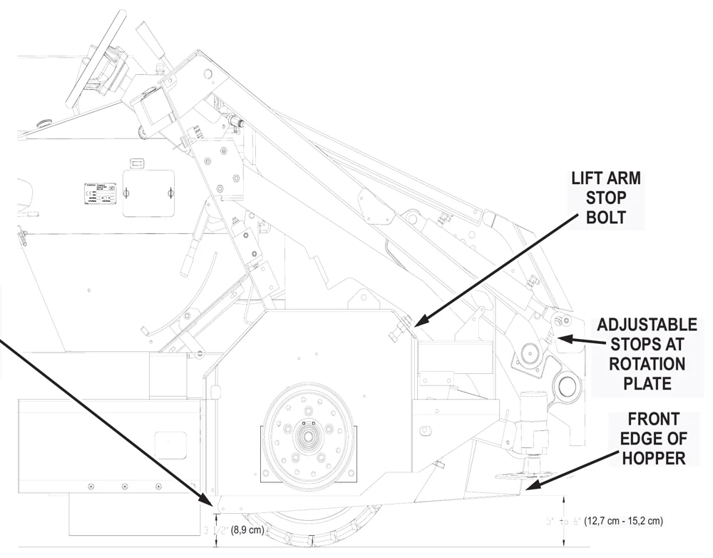
Callouts: LIFT ARM STOP BOLT; REAR ENTRANCE LIP OF HOPPER; ADJUSTABLE STOPS AT ROTATION PLATE; FRONT EDGE OF HOPPER.
Dimensions shown: (8,9 cm) and (12,7 cm - 15,2 cm).
- After adjustment, with the hopper down, use the two adjustable stops located on the rotation plates on both sides of the hopper to establish 3.5 in (8,9 cm) clearance between the rear hopper entrance lip and the floor.
- After the 3.5 in (8,9 cm) clearance is established, make sure both stops make contact simultaneously. The lower front edge of the hopper should be 5 in - 6 in (12,7 cm - 15,2 cm) from the floor. A balanced adjustment of both sets of adjustment bolts is required to correctly adjust the hopper in the lower position. If the bumper is lower than the frame, after the hopper is correctly adjusted, loosen the bumper attachment bolts and reposition the front bumper.
- Raise the hopper and rotate fully.
- Turn the engine off.
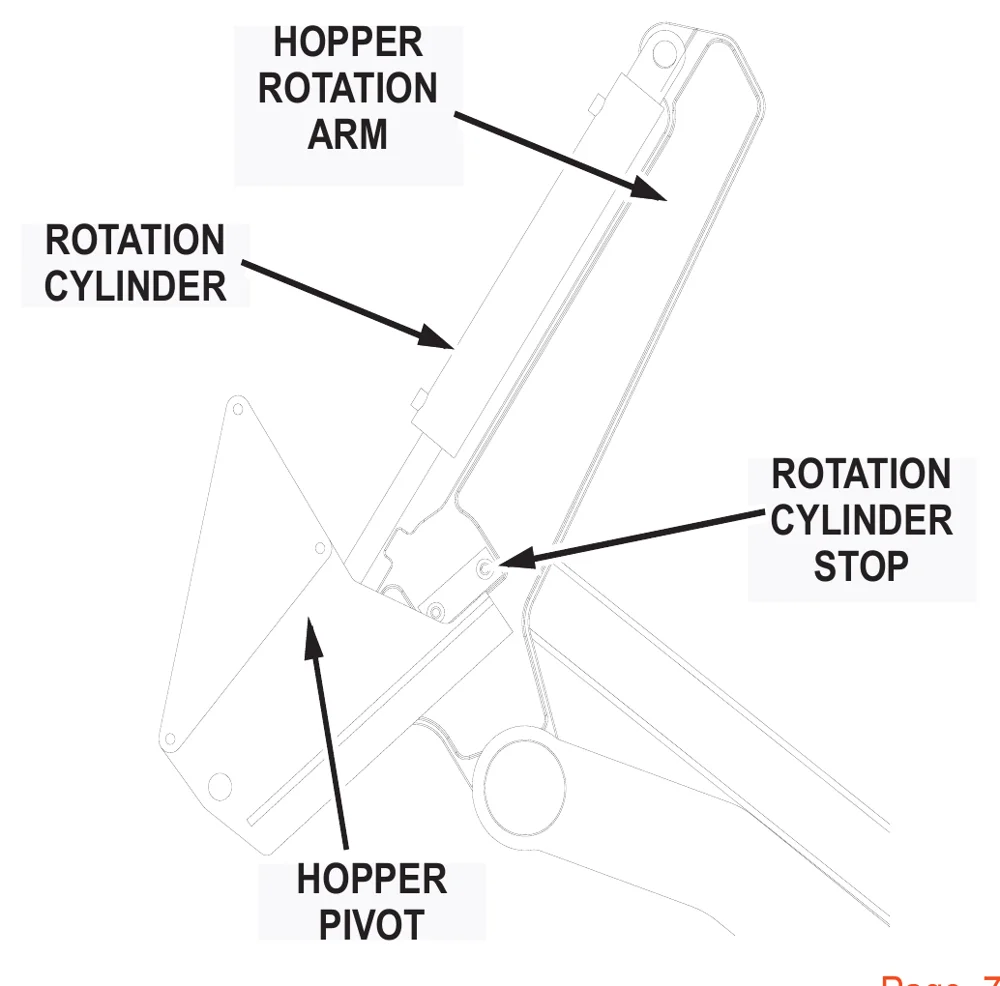
- Adjust the rotation cylinder stops on the hopper rotation arms on each side of the hopper so that clearance between the lift arms and the cut-outs in the bumper is 0.25 in (0,63 cm) maximum.
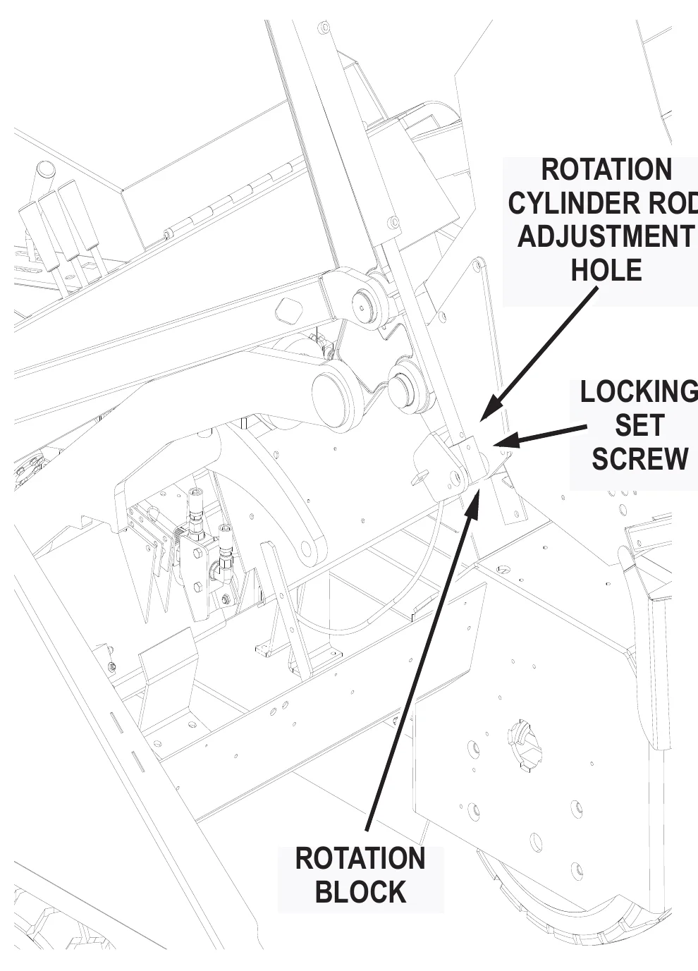
- Loosen the locking set screw in the bottom side of the rotation block.
- Using the hole in the cylinder rod, turn the rod to adjust the cylinder extended length to match the hopper rotation stops.
- Tighten the set screw.
- Rotate the hopper back, remove the safety arm and lower the hopper.
Hopper Filter Removal (Dual Filter)
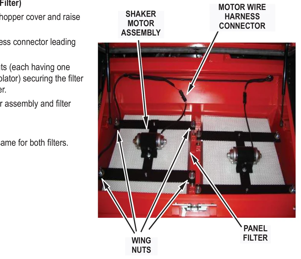
- Release the latch on the hopper cover and raise the cover.
- Disconnect the wire harness connector leading to the filter shaker motor.
- Unscrew the four wing nuts (each having one conical washer and an isolator) securing the filter retainer bars to the hopper.
- Remove the shaker motor assembly and filter retainer bars.
- Lift out the panel filter.
Filter removal steps are the same for both filters.
Filter Cleaning
The dust control filter is a polyester type element filter. It may be vacuumed, blown out with compressed air, tapped against the floor or washed with soap and water.
- If blown out with compressed air, use 100 psi (689 kPa) or less.
- If washed with soap and water, use 40 psi (275 kPa) water pressure or less.
Do not install or use a wet filter.
Filter Replacement
- Insert the panel filter.
- Install the shaker motor assembly.
- Install and tighten the four filter wing nuts, washers, and isolators.
- Reconnect the wire harness connector to the filter shaker motor.
- Close the hopper cover and secure the latch.
Vacuum Gasket Mount Adjustment
- With the hopper in the normal position, observe contact between the back of the hopper and gasket. If complete seal is not maintained, raise the high dump hopper.
Loosen the mounting bolts in the gasket mount. Move the assembly toward the hopper. Tighten the bolts. Test and repeat if necessary.
Flap Replacement
Flaps located at the entrance lip and on the sides of the hopper must be replaced when worn or damaged. The flap panels may be replaced separately.
- Park the machine on a level surface and engage the parking brake.
- Raise the hopper.
- Turn off the engine
- Remove the flap retaining angle and worn or damaged flaps.
- Install the new flaps.
- Replace the retaining angle.
Frame Seal Replacement
Front Frame Seal
The hopper frame seal bolts to the front edge of the engine pan. Install a new seal by folding it in half to align the holes. Doubled edge with holes goes on the bottom. Support the seal straight up while bolting the retainer bar in place. The seal should fall over the retainer bar after installation. Be certain that the seal edges are aligned to prevent twisting of the seal.
Side Frame Seal
The side frame seals should clear the floor by at least .125 in (0,32 cm). If the bottom of a side seal measures .50 in (1,27 cm) or more above the floor, readjust it or replace it by removing the bolts on the inside of the wheel wells, installing a new seal, and securing it with the bolts. The double edge with the holes goes toward the front.
PARKING BRAKE
Normal adjustment of the parking brake can be accomplished from the operator compartment. Locate the knurled handle on the parking brake lever. Turn the handle clockwise to increase brake tension.
If this adjustment becomes ineffective, it will be necessary to adjust the cable length.
Adjusting The Parking Brake Cable Length
- Park the machine on a level surface and chock the wheels.
- Place the parking brake lever in the “OFF” position.
- Turn the knurled handle counter-clockwise as far as possible.
- Raise the hopper and engage the safety arm.
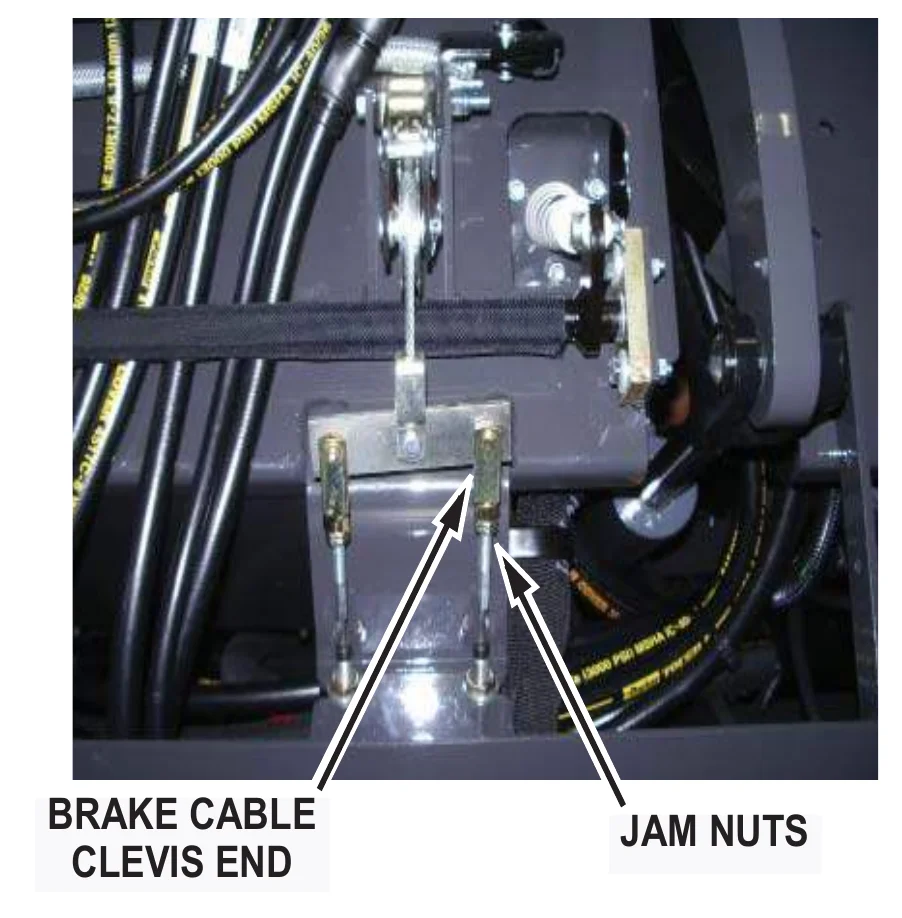
- Locate the cable clevis ends for the parking brake cables.
- Disconnect the clevis ends from the bar.
- Loosen the jam nuts at the base of the clevis.
- Turn the clevis clockwise three or four complete turns.
- Tighten the jam nuts and re-install the clevis ends onto the bar.
- Adjust the knurled handle on the parking brake lever.
TIRES
Changing Solid Tires
- Remove the tire from the vehicle by removing the five inner lug nuts.
- Remove the ten hex head bolts and nuts.
- Press the tire from the rim.
- Press the large rim half into the new tire.
- Mount the small rim half and secure with hex head bolts.
- Reinstall the tire on the machine.
Changing Pneumatic Tires
PowerBoss® recommends that you have these tires changed by a professional tire dealer.
Tires are to be inflated to 100 psi (689 kPa).
MISCELLANEOUS ADJUSTMENTS
Anti-Static Chain Adjustment
Each machine is equipped with an anti-static chain bolted to the back wall of the broom chamber. This should remain in contact with the floor at all times. Inspect the chain every 200 operating hours. Replace if at least one link does not drag the surface of the floor.
Latch and Hinge Maintenance
Latches and hinges should be inspected after every 500 hours of use. Retighten and oil if necessary.
Cables
Inspect all cables for wear every 500 hours.
TROUBLESHOOTING
This section provides information to assist in identifying maintenance trouble and provides possible causes and actions to correct the problem. Many of the solution require servicing your machine, they can be found in the service manual for you unit. Service must be preformed by an approved authorized repair station.
| TROUBLESHOOTING CHART | ||
|---|---|---|
| PROBLEM | POSSIBLE CAUSE(S) | SOLUTION(S) |
| Engine will not start or runs roughly after start. | Battery dead. | Recharge or replace battery. |
| Machine out of fuel. | Refuel | |
| Fuel filter plugged. | Clean or replace filter. | |
| Fuel line broken or obstructed. | Blow fuel line out with compressed air. | |
| Dirty air filter. | Clean or replace air filter. | |
| Problems with spark plugs, ignition coil, ignition switch, regulator, wiring harness. | Review engine manual for maintenance and troubleshooting procedures. | |
| Additionally with LP fuel, check the following: | Tank valve not fully opened. | Open the valve slowly. |
| Fuel tank type does not match fuel supply. | Use the correct tank type for the fuel supply. | |
| Fuel tank and lines are covered with frost. | Open shut-off valve slowly to ¼ open, start. | |
| Defective vacuum lock-off. | Replace or repair. | |
| Additionally with Diesel fuel, check the following: | Cold weather start with Glow plugs | See Starting instructions, page 34. |
TROUBLESHOOTING CHART
| PROBLEM | POSSIBLE CAUSE(S) | SOLUTION(S) |
|---|---|---|
| Engine overheats. NOTE: If coolant loss has not occurred, check for malfunction of the temperature sending unit. | Low coolant level. | Supply coolant. |
| Clogged radiator. | Flush radiator. | |
| Loose fan belt. | Tighten belt. | |
| Defective thermostat. | Replace thermostat. | |
| PowerBoss® machine creeps in neutral. | Directional control pedal return spring is out of adjustment. | Perform the adjustment procedures. |
| Brushes do not turn or turn very slowly. | Hydraulic system problem: | See Hydraulics System Problems in this section. |
| Motor | ||
| Control valve | ||
| Gear pump | ||
| Relief valve | ||
| Little or no vacuum in brush compartment. | Filters clogged. | Clean filters. |
| Leak or clog in hose from impeller. | Repair leaks; clear obstructions or replace hose. | |
| Impeller failure. | Check and repair. |
TROUBLESHOOTING CHART
| PROBLEM | POSSIBLE CAUSE(S) | SOLUTION(S) |
|---|---|---|
| PowerBoss® machine moves slowly or does not move. | Parking brake is on. | Release brake. |
| Directional control pedal jammed, damaged, or not adjusted properly. | Clear jam or adjust linkage. | |
| Tires skidding from contact with oil or grease. | Clean tires or drive through a solvent absorbing substance. | |
| Wheels jammed. | Clear jam. | |
| Low hydraulic fluid level. | Add hydraulic fluid. | |
| Hydraulic fluid temperature too high and too thin caused by excessive load, climbing, high environment temperatures, worn pump, or improper fluid. | Use the proper weight oil for the operation conditions; check pump. | |
| Damaged or worn pump drive coupling. | Replace damaged item. | |
| Other problems with the hydraulics system: pump failure, motor failure, relief valve leaking or stuck open. | See Hydraulics System Problems in this section. |
TROUBLESHOOTING CHART
| PROBLEM | POSSIBLE CAUSE(S) | SOLUTION(S) |
|---|---|---|
| Loss of dust control. | Debris in hose or impeller inlet. | Clean. |
| Broom skirts or seal worn. | Replace. | |
| Skirt clearance from floor exceeds .125 in (0,32 cm). | Adjust clearance. | |
| Dust control filters clogged. | Clean filters. | |
| Filter seals worn or missing. | Replace. | |
| Poor seal with vacuum gasket. | Visually check and adjust, if necessary. | |
| Sweeper unit leaving debris. | Hopper full. | Dump hopper. |
| Broom(s) out of adjustment. | Adjust. | |
| Broom bristles worn. | Check broom for wear and adjustment. | |
| Poor performance of broom drive mechanism. | Check for jam in broom chamber. | |
| Broom lift arms hung up with debris. | Clear out debris. | |
| Hopper flaps damaged or missing. | Replace or adjust clearance. | |
| Hopper out of adjustment. | Check hopper clearance. | |
| Dust control filters clogged. | Clean filters. |
TROUBLESHOOTING CHART
| PROBLEM | POSSIBLE CAUSE(S) | SOLUTION(S) |
|---|---|---|
| Hopper does not raise or lower. | Hydraulics system problem:
| See Hydraulics Systems Problems in this section. |
| Hopper arms binding. | Lubricate or adjust arm linkage. | |
| Hopper lift cylinder failure. | Line to cylinder leaking. | Tighten fittings or replace hose. |
| Piston seals leaking. | Replace seals. | |
| Bent piston rod. | Replace rod. | |
| Hopper does not rotate or rotates too slowly. | Hopper load too heavy. | Dump more frequently. |
Hydraulics system problem:
| See Hydraulics System Problems in this section. |
TROUBLESHOOTING CHART
| PROBLEM | POSSIBLE CAUSE(S) | SOLUTION(S) |
|---|---|---|
| Hydraulic control valve failure | Misaligned control linkage. | Align. |
| Foreign matter in spool bore. | Remove spool and clean bore. | |
| Valve seals Leaking. | Replace seals. | |
| O-rings leaking. | Replace O-rings | |
| Relief valve stuck open. | Clean or replace relief valve. | |
| Hydraulic motor failure. | Motor leaking. | Replace seals. |
| Drive link malfunction. | Replace drive link. | |
| Output shaft malfunction. | Replace output shaft and bearings. | |
| Hydraulic gear pump failure. | Pump leaking. | Replace seals or RR Pump |
| Gears worn or scored. | Rebuild pump or RR Pump | |
| Relief valve stuck. | Clean or replace (at control valve). | |
| Oil supply low. | Check and fill. | |
| Oil strainer clogged. | Replace strainer (inside reservoir). | |
| Incorrect oil. | Use recommended viscosity oil. | |
| Damage due to entry of air into hydraulic system. | Maintain correct hydraulic fluid level in reservoir. Keep suction hose fittings tight. |
TROUBLESHOOTING CHART
| PROBLEM | POSSIBLE CAUSE(S) | SOLUTION(S) |
|---|---|---|
| Hydraulic variable displacement pump failure. | Pump leaking. | Replace seals. |
| Relief valve(s) stuck. | Clean or replace relief valve(s) at the pump. | |
| Drive coupling malfunction. | Replace defective gears. | |
| Control linkage out of adjustment. | Check to see if linkage is binding unfastened. | |
| Charge pump gears worn or scored. | Replace defective gears. | |
| Damage due to entry of air into hydraulic system. | Maintain correct hydraulic fluid level in reservoir. Keep suction hose fittings tight. | |
| Hydraulic system noisy. | Air in system. | Check fluid level in reservoir; check for loose connections or leaks. |
| Relief valve dirty or damaged. | Clean or replace. | |
| Loose suction line. | Tighten fittings. | |
| Clogged section filter or pump inlet line. | Replace filter, clear line; change fluid in reservoir if dirty and flush system. | |
| Internal pump or motor damage. | Inspect and repair. |
CE DECLARATION OF CONFORMITY
GB EC Declaration of Conformity (according to Directive 2006/42/EC)
PowerBoss Inc.
declare under our sole responsibility, that the product,
Machine
Armadillo 9XR LP (9XRLPGCE)
Armadillo 9XR Diesel (9XRDSLCE)
to which this declaration relates corresponds to the relevant basic safety and health requirements of the Directive 2006/42/EC, and to the requirements of the other relevant Directives 2004/108/EC. For the relevant implementation of the safety and health requirements mentioned in the Directives, the following standard(s) and/or technical specification(s) has (have) been respected:
EN 60335-2-72, EN 55012, EN 61000-6-2
Date 6/3/2014
Jack Hill
Vice President of Sales
Name of the person authorized for PowerBoss to compile the technical file:
Jeff Pollack
PowerBoss® is a Full Line Manufacturer of Sweepers and Scrubbers, for Industrial Facilities.
PowerBoss® 14N845 U.S. Route 20 Pingree Grove, Illinois 60140
Phone: 800-323-9420 www.PowerBoss.com e-mail:[email protected]
A Member of the Hako Group
Armadillo 9X Sweeper #4100033 Rev. G 03/22
© 2014-2015 Minuteman International, Inc.
Minuteman and PowerBoss are trademarks of Minuteman International, Inc. Southeastern Equipment & Supply is an independent dealer.