Free Shipping on Equipment & Parts orders of $200 or more! * Click for Restrictions

Have a question? 800-440-6723 International: 803-252-0100

English Se habla español
Parts › PartFinder › Kaivac 1200 Series › Operator manual
Form KV1200_Manual_12-02-2016, Rev. 12-2016
Kaivac · Cleaning machine

Kaivac 1200 Series Operator Manual

KV1200_Manual_12-02-2016 Rev. 12-201633 pagesKaivac 1200 Series Manual (KV1215, KV1220, KV1250)
Free to read, no account neededEvery page has its own linkPart numbers link to the part
COVER

Operator & Parts Manual

KaiVac® 1200 Series‌‌​⁠​‍​‌‍​⁠​‍⁠​​​‌‌‍​​​​​​​‌​​​‌​⁠​​‌‌‍⁠​​‍​⁠​​‌‍‍​‍‍⁠‍‍‍​‌‌

1215 Serial Number 415-
1250 Serial Number 3309-
CE1250 215-
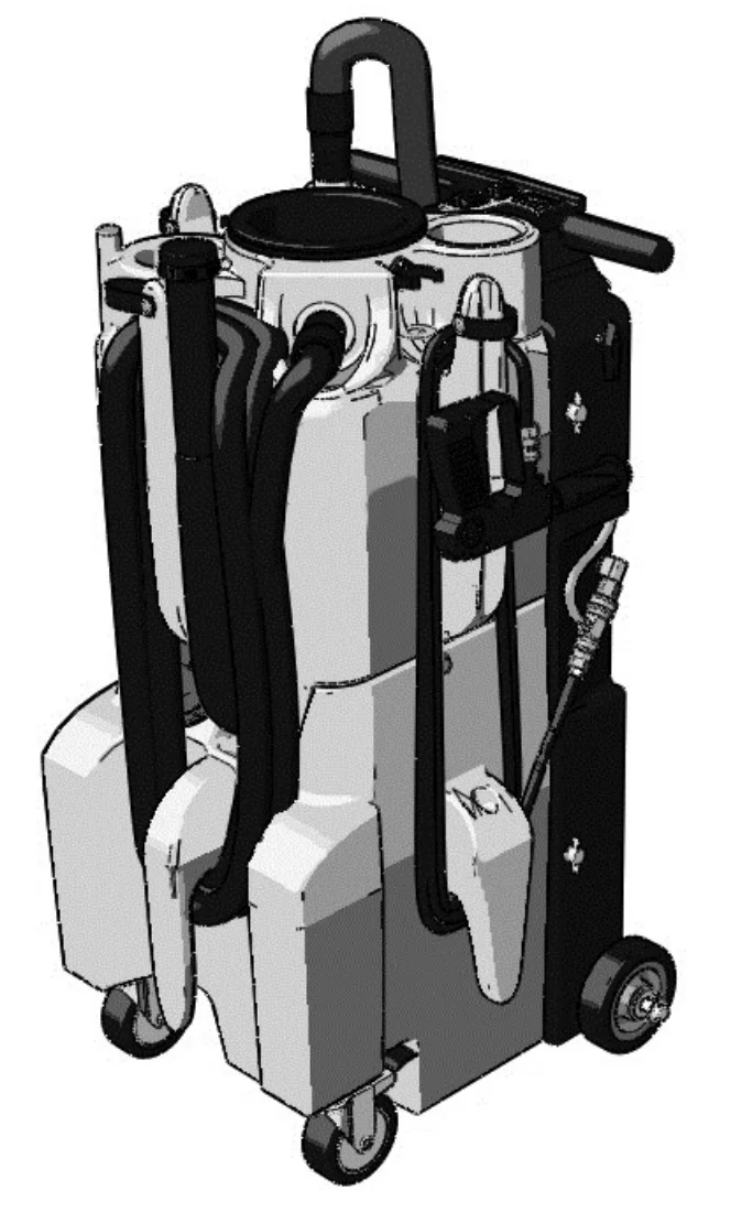
Drawing of the KaiVac 1200 Series machine on wheels, with a tall tank body, a black handle at the upper right, a looped vacuum pipe on top, and hoses and a spray gun hanging on the sides

www.kaivac.com

© 2006-2013 Kaivac, Inc. All Rights Reserved

Source: Kaivac 1200 Series Operator Manual KV1200_Manual_12-02-2016 Rev. 12-2016, page 1, used with permission. SES ref PF-KDB4-CH5H‌‌​⁠​‍​‌‍​⁠​‍⁠​​​‌‌‍​​​​​​​‌​​​‌​⁠​​‌‌‍⁠​​‍​⁠​​‌‍‍​‍‍⁠‍‍‍​‌‌
1200 Series KV1200_Manual_12-02-2016 (12-2016)Page 1 of 33
REVISION SHEET

Revision Sheet

In short This sheet lists the releases of the Kaivac operator and parts manual with their dates and what changed. Two releases are recorded: the original release and a warranty change.‌‌​⁠​‍​‌‍​⁠​‍⁠​​​‌‌‍​​​​​​​‍​​​‌​⁠​​‍​‌​‌‌⁠​⁠⁠‍​⁠‍‍‍​‍‍‌‍⁠⁠‍
Release No.DateRevision Description
10141310/14/13Operator & Parts Manual Released
12171312/17/13Modified Rotomold Warranty to 5 years.
NOTE: Specifications and parts are subject to change without notice

Kaivac, Inc.‌‌​⁠​‍​‌‍​⁠​‍⁠​​​‌‌‍​​​​​​​‍​​​‌​⁠​​‍​‌​‌‌⁠​⁠⁠‍​⁠‍‍‍​‍‍‌‍⁠⁠‍

401 S. Third Street

Hamilton, OH 45011

Source: Kaivac 1200 Series Operator Manual KV1200_Manual_12-02-2016 Rev. 12-2016, page 2, used with permission. SES ref PF-SP4V-BZFE‌‌​⁠​‍​‌‍​⁠​‍⁠​​​‌‌‍​​​​​​​‍​​​‌​⁠​​‍​‌​‌‌⁠​⁠⁠‍​⁠‍‍‍​‍‍‌‍⁠⁠‍
1200 Series KV1200_Manual_12-02-2016 (12-2016)Page 2 of 33
TABLE OF CONTENTS

OPERATOR & PARTS MANUAL

No.TitlePage #
1.0GETTING STARTED1-1
1.1Limited Warranty Protection Plan1-1
1.2Warranty Registration Form1-2
1.3Safety Precautions1-3
2.0OPERATION2-1
2.1Out-of-Box Setup Instructions2-1
2.2Kaivac Tool Arrangement2-2
2.3Preparing Your Kaivac For Use2-3
2.41200 Series Vac Tank Horn Operation2-4
2.5Operating your Kaivac using S-I-M-P-L-E Process2-5
3.0MAINTENANCE3-1
3.1Maintenance3-1
3.2Squeegee Head Maintenance3-2
3.3Black Box Removal Instructions3-3
3.4Troubleshooting3-4
3.5Machine Diagrams3-7
3.6Parts List3-19
Source: Kaivac 1200 Series Operator Manual KV1200_Manual_12-02-2016 Rev. 12-2016, page 3, used with permission. SES ref PF-FG3L-W6HY‌‌​⁠​‍​‌‍​⁠​‍⁠​​​‌‌‍​​​​​​​⁠​​​‌​⁠​​‌​​⁠​​‌⁠‍​​‌⁠‍​​‍⁠‌​‍​‍‌
1200 Series KV1200_Manual_12-02-2016 (12-2016)Page 3 of 33
1.0 GETTING STARTED

1.0 GETTING STARTED

1.1 Limited Warranty Protection Plan

In short This section explains the warranty periods for the machine, which depend on the chemicals used. Warranty claims need a Return Authorization Number (RAN) from Kaivac Customer Service, and wear items are excluded.‌‌​⁠​‍​‌‍​⁠​‍⁠​​​‌‌‍​​​​​​‌​​​​‌​⁠​​‌‌⁠​​‍​​⁠⁠⁠‌‍⁠‌​‌⁠‌⁠​⁠​⁠

The Kaivac has been engineered and tested to provide long lasting performance. This warranty covers defects in workmanship or materials under normal use and service from the date of purchase.‌‌​⁠​‍​‌‍​⁠​‍⁠​​​‌‌‍​​​​​​‌​​​​‌​⁠​​‌‌⁠​​‍​​⁠⁠⁠‌‍⁠‌​‌⁠‌⁠​⁠​⁠

Kaivac, Inc. warrants the following components to be free from defects in materials and workmanship for these time periods:

1.) Extended Warranty for end users who use only Kaivac chemicals for the life of the machine.

  • 5 years on rotationally molded parts
  • 3 years on other parts (excluding wear items)
  • 1 year on labor

2.) Standard Warranty (for approved non-Kaivac chemicals)

  • 1 year parts and labor

3.) Chemicals that have not been approved by Kaivac (If uncertain, please contact Kaivac to verify your chemical before using).

  • No warranty

All Kaivac replacement parts are guaranteed for 90 days from the date of installation. Normal wear items such as wheels, hoses, seals, gaskets, cords, casters, squeegees and GFCI are excluded from warranty coverage.

All warranty claims must be accompanied by a Return Authorization Number (RAN), which is available by calling the Kaivac, Inc. Customer Service Department. No returns will be accepted without a RAN.

This warranty does not apply to return freight costs, damage or defect caused by accident, negligence, misuse, fire or repair done by anyone other than a Kaivac authorized repair center. In no event shall Kaivac, Inc. be liable for incidental or consequential damages, or any damages to persons or property.

Please Note: Under no circumstances will the seller be liable for any loss, damage, expenses or consequential damages arising in connection with the use or inability to use seller’s product. Kaivac, Inc. reserves the right to make changes or improvements to its equipment without notice. Some states do not allow the exclusion or limitation of incidental or consequential damages. This warranty is in lieu of any other warranty expressed or implied, including any warranty of merchantability or fitness for a particular purpose.

Source: Kaivac 1200 Series Operator Manual KV1200_Manual_12-02-2016 Rev. 12-2016, page 4, used with permission. SES ref PF-UAM5-KSET‌‌​⁠​‍​‌‍​⁠​‍⁠​​​‌‌‍​​​​​​‌​​​​‌​⁠​​‌‌⁠​​‍​​⁠⁠⁠‌‍⁠‌​‌⁠‌⁠​⁠​⁠
1200 Series KV1200_Manual_12-02-2016 (12-2016)Page 4 of 33
1.0 GETTING STARTED

1.2 WARRANTY REGISTRATION FORM

In short This is the warranty card the customer purchasing the equipment fills in. It must be mailed or faxed to Kaivac, Inc. within ten days of purchase.‌‌​⁠​‍​‌‍​⁠​‍⁠​​​‌‌‍​​​​​​‌‌​​​‌​⁠​​‍​⁠‍⁠‍​‍‌‍‍‍‍​⁠‌​⁠‌​⁠​‌‌

To be completed and mailed or faxed by the customer purchasing equipment. Return this warranty card within ten days of purchase.‌‌​⁠​‍​‌‍​⁠​‍⁠​​​‌‌‍​​​​​​‌‌​​​‌​⁠​​‍​⁠‍⁠‍​‍‌‍‍‍‍​⁠‌​⁠‌​⁠​‌‌

Purchased By:

Name: ____________________________________________ Title: _____________________________

Company: ___________________________________________________________________________

Street Address: _______________________________________________________________________

City: ____________________________________ State: ___________ Zip Code: _________________

  • KV1750
  • KV1250
  • KV2150
  • KV1715AC
  • KV1715
  • KV1215
  • OMNIFLEX Pump Box
  • OMNIFLEX Wet/Dry Vac

Serial Number: __________________

Type of Business

  • School/University
  • Hospital/Health Care
  • Contract Cleaner
  • Industrial
  • Office
  • Other: _____________

Intended Uses (check all that apply)

  • Restroom Cleaning
  • Floor Stripping
  • Kitchen Cleaning
  • Carpet Extraction
  • Cleaning Around Machines
  • Stairwell Cleaning
  • Lockers & Showers
  • Hallway Cleaning
  • Classroom Cleaning
  • Other: ____________

Thank you for registering for our warranty program.

Please return completed forms to:
Kaivac, Inc.
401 S. Third Street
Hamilton, OH 45011
Or Fax to: (513) 887-4601

Source: Kaivac 1200 Series Operator Manual KV1200_Manual_12-02-2016 Rev. 12-2016, page 5, used with permission. SES ref PF-6CUL-T4ZQ‌‌​⁠​‍​‌‍​⁠​‍⁠​​​‌‌‍​​​​​​‌‌​​​‌​⁠​​‍​⁠‍⁠‍​‍‌‍‍‍‍​⁠‌​⁠‌​⁠​‌‌
1200 Series KV1200_Manual_12-02-2016 (12-2016)Page 5 of 33
1.0 GETTING STARTED

1.3 SAFETY PRECAUTIONS

In short This section lists the safety rules for using the Kaivac, mainly to avoid electric shock and injury. The unit must be connected to a properly grounded outlet, the cord and GFCI checked before each use, and the discharge stream never pointed at people.‌‌​⁠​‍​‌‍​⁠​‍⁠​​​‌‌‍​​​​​​‌‍​​​‌​⁠​​‌⁠​‍‌‍‍‍‌‌⁠​⁠‌‌​‌‍‍⁠⁠‍‌​

IMPORTANT SAFETY INSTRUCTIONS—SAVE THESE INSTRUCTIONS‌‌​⁠​‍​‌‍​⁠​‍⁠​​​‌‌‍​​​​​​‌‍​​​‌​⁠​​‌⁠​‍‌‍‍‍‌‌⁠​⁠‌‌​‌‍‍⁠⁠‍‌​

CAUTION: To reduce the risk of injury, read operating instructions carefully before using.
WARNING: Risk of injection or injury to persons – do not direct discharge stream at persons.
WARNING RISK OF ELECTROCUTION:
  • Connect to a properly grounded outlet. Do not remove ground pin.
  • Inspect cord before using – do not use if cord is damaged.
  • Keep all connections dry and off the ground.
  • Do not touch plug with wet hands.
  • This product is provided with a ground fault circuit interrupter built into the power cord. If replacement of the plug or cord is needed, use only identical replacement parts.
  • Test the ground fault circuit interrupter (GFCI) before each use.
  • Do not close a door on the cord or pull the cord around sharp edges or corners.
  • Keep the cord away from heated surfaces.
  • Do not spray liquid from the Kaivac onto electrical outlets or on any electrical devices.
  • Turn off the unit before unplugging.
  • Do not pull on the cord to unplug. Grasp the plug at the outlet and pull.

Grounding Instructions:

THE KAIVAC MUST BE GROUNDED. If it should malfunction or stop working, grounding provides a path of least resistance for the electrical current and reduces the risk of electrical shock. The Kaivac is equipped with a ground fault circuit interrupter (GFCI) to further reduce danger and risk of electric shock. It must be maintained and tested regularly. An equipment grounding cord and plug is included with the unit. Cutting off the ground wire or using a cord with an ungrounded plug will void the warranty on the Kaivac.

Improper connection of the equipment grounding cord can result in the risk of electrical shock. Ask a qualified electrician or service person to check the outlet grounding if you are unsure. Do not modify the plug provided with the Kaivac. If it will not fit into the outlet, have a properly grounded outlet installed by a qualified electrician.

WARNING: When using this product, basic precautions should always be followed, including the following:
  • Read all the instructions before using the product.
  • To reduce the risk of injury, close supervision is necessary when a product is used near children.
  • Know how to stop the product and bleed pressures quickly. Be thoroughly familiar with the controls.
  • Stay alert – watch what you are doing.
  • Do not operate the product when fatigued or under the influence of alcohol or drugs.
  • Keep operating area clear of all persons.
  • Do not overreach or stand on unstable support. Keep good footing and balance at all times.
  • Do not use to pick up flammable or combustible materials.
  • Follow the maintenance instructions specified in the manual.

Personal Protective Equipment (PPE): It is recommended to wear proper personal protective equipment as required by the chemical product label instructions used in conjunction with the Kaivac.

FOR INDOOR USE ONLY

Source: Kaivac 1200 Series Operator Manual KV1200_Manual_12-02-2016 Rev. 12-2016, page 6, used with permission. SES ref PF-G7FX-RNBG‌‌​⁠​‍​‌‍​⁠​‍⁠​​​‌‌‍​​​​​​‌‍​​​‌​⁠​​‌⁠​‍‌‍‍‍‌‌⁠​⁠‌‌​‌‍‍⁠⁠‍‌​
1200 Series KV1200_Manual_12-02-2016 (12-2016)Page 6 of 33
2.0 OPERATION

2.1 OUT-OF-BOX SETUP INSTRUCTIONS

In short This section shows how to set up the machine after unboxing in five steps. You join the vac wand sections, attach the plastic elbow and the vac motor hose to the machine, place the tools and hoses in their locations, and assemble the vacuum hoses.‌‌​⁠​‍​‌‍​⁠​‍⁠​​​‌‌‍​​​​​​‌⁠​​​‌​⁠​​​⁠⁠​‌‌⁠⁠​‌⁠‍‌⁠​​⁠⁠⁠​⁠​​​
  1. Remove vac wand sections from the accessory box and attach together until locking pin engages as shown
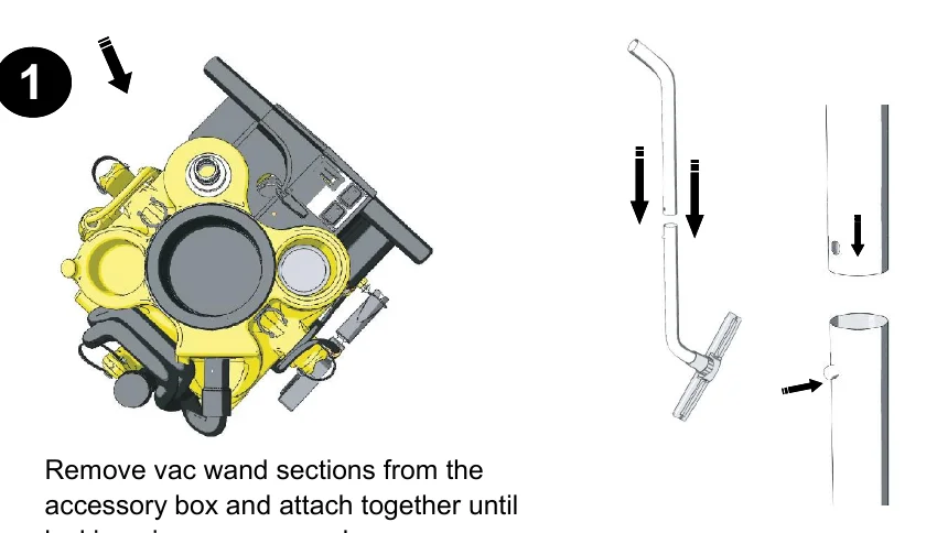
    Machine seen from above with an arrow pointing to it, next to two vac wand sections with arrows showing the sections being pushed together until the locking pin engages
    1
  2. After removing machine from container, attach the plastic elbow to the vac tank as shown above
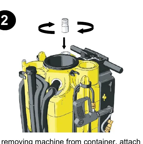
    Plastic elbow fitting being lowered with an arrow onto the vac tank opening, with curved arrows showing it being turned
    2
  3. SMALL HOSE
    Attach vac motor hose to barb and vac motor inlet as shown above
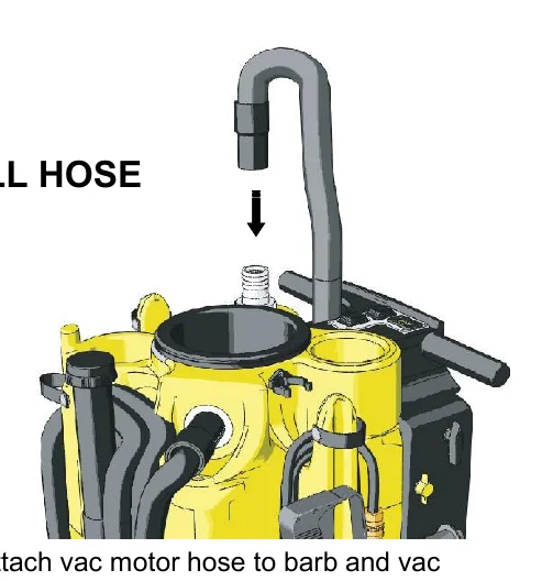
    Small hose with a downward arrow being attached to the barb at the vac motor inlet on top of the machine
    3
  4. Remove the tools and hoses from the accessory box and place them in the appropriate locations as shown above. Place extra tools in tote bag and hang bag over nose of machine.
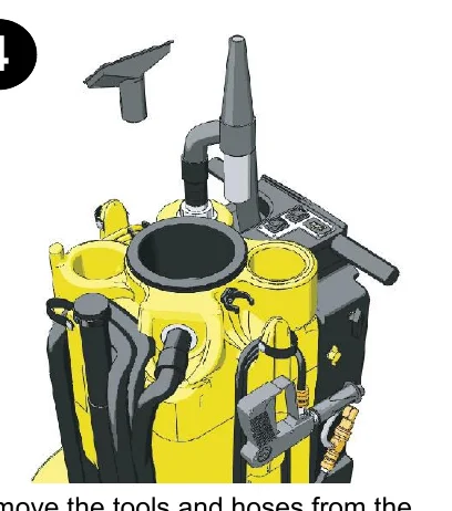
    Machine with a crevice tool and a wand tool above it, showing tools and hoses placed in their storage locations on the machine
    4
  5. Remove the Vacuum Hoses from the Accessory Box. Assemble as shown.
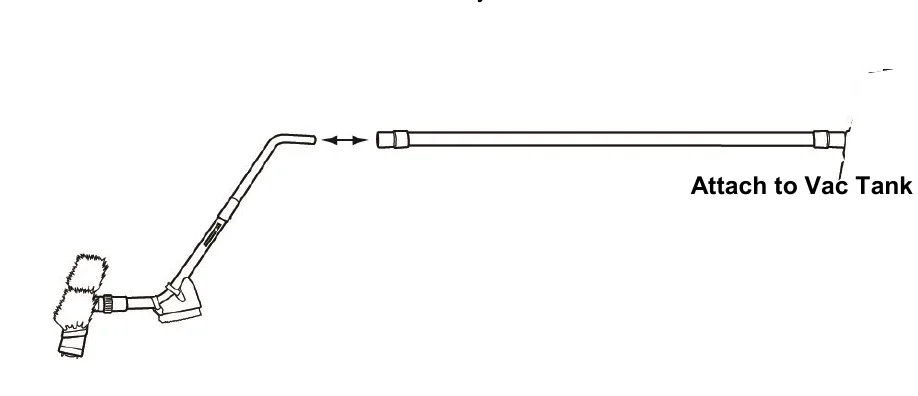
    Assembled vacuum hose and wand with a floor tool, a double-headed arrow showing the hose connecting to the wand, and a label Attach to Vac Tank at the hose end
    5
Source: Kaivac 1200 Series Operator Manual KV1200_Manual_12-02-2016 Rev. 12-2016, page 7, used with permission. SES ref PF-UAPW-2BW6‌‌​⁠​‍​‌‍​⁠​‍⁠​​​‌‌‍​​​​​​‌⁠​​​‌​⁠​​​⁠⁠​‌‌⁠⁠​‌⁠‍‌⁠​​⁠⁠⁠​⁠​​​
1200 Series KV1200_Manual_12-02-2016 (12-2016)Page 7 of 33
2.0 OPERATION

2.2 KAIVAC TOOL ARRANGEMENT

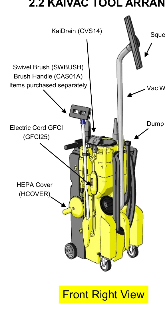
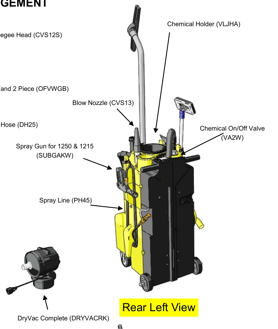
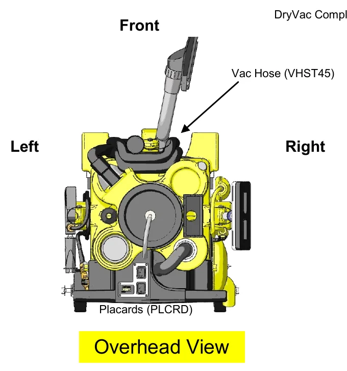
In short This page shows where each tool and part is located on the machine, using four views: front right, rear left, overhead and bottom. Each part is labeled with its name and part code.‌‌​⁠​‍​‌‍​⁠​‍⁠​​​‌‌‍​​​​​​‍​​​​‌​⁠​​⁠‍‍​​‌​‌⁠‍‍‍‌​‍‍⁠‌‍‌​​⁠​
Front right view of the machine with callouts for KaiDrain (CVS14), Squeegee Head (CVS12S), Swivel Brush (SWBUSH) and Brush Handle (CAS01A) purchased separately, Vac Wand 2 Piece (OFVWGB), Dump Hose (DH25), Electric Cord GFCI (GFCI25) and HEPA Cover (HCOVER)
Front Right View
Rear left view of the machine with callouts for Chemical Holder (VLJHA), Blow Nozzle (CVS13), Chemical On/Off Valve (VA2W), Spray Gun for 1250 & 1215 (SUBGAKW) and Spray Line (PH45)
Rear Left View
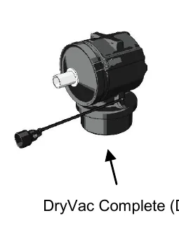
DryVac Complete unit (DRYVACRK), a round black canister with a cord, shown with an arrow from its label
DryVac Complete (DRYVACRK)
Overhead view of the machine with front at top, left and right marked, and callouts for Vac Hose (VHST45) and Placards (PLCRD)
Overhead View
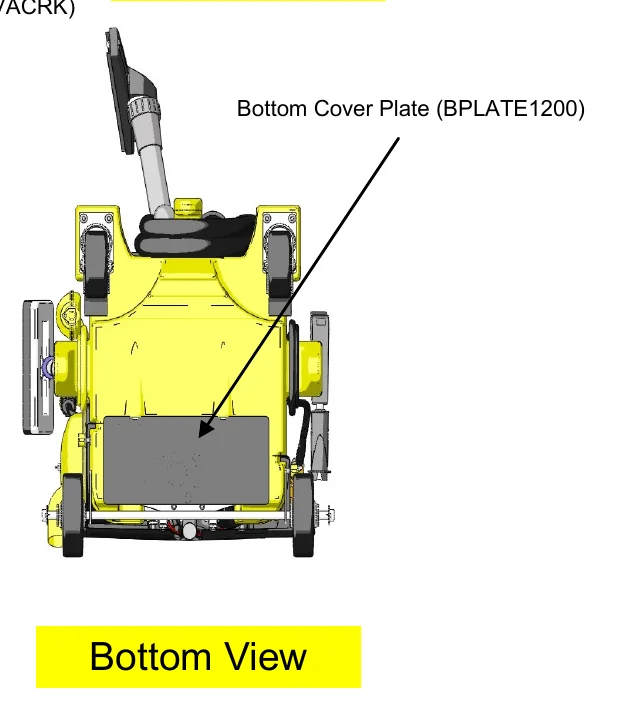
Bottom view of the machine with a callout arrow to the Bottom Cover Plate (BPLATE1200)
Bottom View
Source: Kaivac 1200 Series Operator Manual KV1200_Manual_12-02-2016 Rev. 12-2016, page 8, used with permission. SES ref PF-T3T3-BLG6‌‌​⁠​‍​‌‍​⁠​‍⁠​​​‌‌‍​​​​​​‍​​​​‌​⁠​​⁠‍‍​​‌​‌⁠‍‍‍‌​‍‍⁠‌‍‌​​⁠​
1200 Series KV1200_Manual_12-02-2016 (12-2016)Page 8 of 33
2.0 OPERATION

2.3 PREPARING YOUR KAIVAC FOR USE

In short This section lists six checks to make before cleaning: fill the machine with water, prepare the cleaning solution, check tools and supplies, control foam if needed, inspect hoses and spray lines, and test the GFCI.‌‌​⁠​‍​‌‍​⁠​‍⁠​​​‌‌‍​​​​​​‍‌​​​‌​⁠​​⁠‍⁠‌⁠​‍⁠‍⁠⁠​​‌​⁠‍‍⁠​‌‍‌‍

*Applicable to all units, but KV1700 Series shown for illustration‌‌​⁠​‍​‌‍​⁠​‍⁠​​​‌‌‍​​​​​​‍‌​​​‌​⁠​​⁠‍⁠‌⁠​‍⁠‍⁠⁠​​‌​⁠‍‍⁠​‌‍‌‍

  1. Fill machine with clean, cool water.
    Hand pouring water into the open top of the machine to fill it
  2. Prepare the cleaning solution you will be using by attaching the chemical feed line and cap to the top of your chemical bottle and selecting the proper metering tip. (See placard for metering tip information)
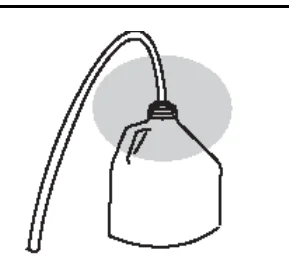
    Chemical bottle with the feed line and cap attached to its top, the line running up and away
  3. Check machine for all tools and supplies needed to complete task. See “Tool Arrangement” in Section 2.2 of this manual.
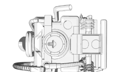
    Top view of the machine used to check that all tools and supplies are in place
  4. If using a cleaning product that has high foaming use a foam inhibitor to cut down on foam. Pour 2 capfuls of inhibitor in the vac hose with vac running to coat inside of hose.
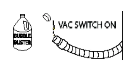
    Foam inhibitor bottle labeled Bubble Buster with its cap off beside the vac hose, marked VAC SWITCH ON
  5. Check all hoses and spray lines for damage prior to use. If damage is found, do not continue until proper repairs are completed.
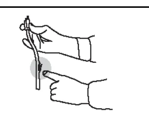
    Gloved hands checking a hose or spray line for damage
  6. Plug in machine and test GFCI (Ground Fault Circuit Interrupter) to ensure it is working properly. You are now ready.
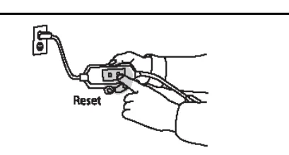
    Power cord plugged into a wall outlet with a gloved hand pressing the Reset button on the GFCI
Source: Kaivac 1200 Series Operator Manual KV1200_Manual_12-02-2016 Rev. 12-2016, page 9, used with permission. SES ref PF-AZG6-QGD4‌‌​⁠​‍​‌‍​⁠​‍⁠​​​‌‌‍​​​​​​‍‌​​​‌​⁠​​⁠‍⁠‌⁠​‍⁠‍⁠⁠​​‌​⁠‍‍⁠​‌‍‌‍
1200 Series KV1200_Manual_12-02-2016 (12-2016)Page 9 of 33
2.0 OPERATION

2.4 1200 SERIES VAC TANK HORN OPERATION

In short This section shows how to get the vacuum hose off the vac tank horn and ready for extracting. You connect the wand and hose, rotate the horn, slide the hose onto the floor, then turn on the vac motor.‌‌​⁠​‍​‌‍​⁠​‍⁠​​​‌‌‍​​​​​​‍‍​​​‌​⁠​​‌‌‍‍⁠‌‍​​‌​​‍​‌‌⁠​⁠‌‍‌⁠​
  1. Connect the vacuum wand and slinky hose together
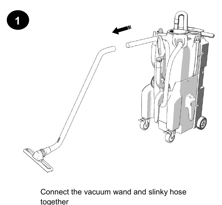
    Step 1: a vacuum wand with floor tool shown separate from the machine, with an arrow pointing toward the slinky hose end on the machine so the two can be connected
    1
  2. Rotate the horn assembly so that it is now pointing towards the front of the machine.
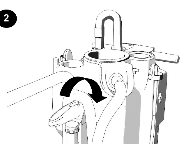
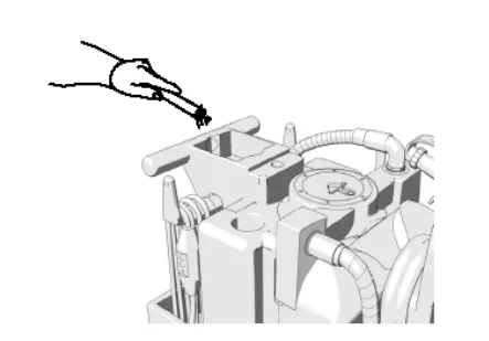
    Step 2: close-up of the top of the vac tank with a curved arrow showing the horn assembly being rotated toward the front of the machine
    2
  3. Place hand behind vac hose and slide forward off of horn onto floor.
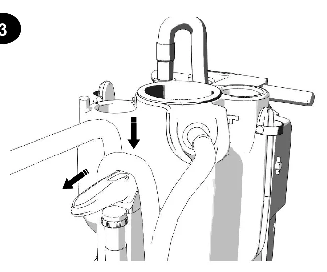
    Step 3: close-up of the vac tank horn with arrows showing the hose being slid forward and down off the horn onto the floor
    3
  4. Once hose is off and on floor turn on vac motor and proceed extracting.
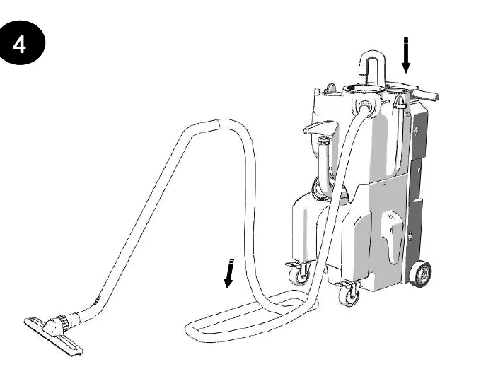
    Step 4: the machine with the vacuum hose lying in a loop on the floor and the wand with floor tool attached, ready for extracting, with arrows showing the hose coming down off the horn
    4
Source: Kaivac 1200 Series Operator Manual KV1200_Manual_12-02-2016 Rev. 12-2016, page 10, used with permission. SES ref PF-4X6V-5NSS‌‌​⁠​‍​‌‍​⁠​‍⁠​​​‌‌‍​​​​​​‍‍​​​‌​⁠​​‌‌‍‍⁠‌‍​​‌​​‍​‌‌⁠​⁠‌‍‌⁠​
1200 Series KV1200_Manual_12-02-2016 (12-2016)Page 10 of 33
2.0 OPERATION

2.5 S.I.M.P.L.E PROCESS

In short This page shows the S.I.M.P.L.E process as a set of illustrated rows: Set-up, Inject, Manual Brush, Pressure wash and rinse, Loop and Extract. It starts with filling the unit with clean, cool water and adding KaiDri, and uses low pressure mode for chemicals and high pressure mode for fresh water.‌‌​⁠​‍​‌‍​⁠​‍⁠​​​‌‌‍​​​​​​‍⁠​​​‌​⁠​​​​⁠⁠‌​‍‍​⁠‍​‍‌‍‍‍⁠‌​‌⁠‍‌

*Applicable to all units, KV1700 Series shown for illustration.‌‌​⁠​‍​‌‍​⁠​‍⁠​​​‌‌‍​​​​​​‍⁠​​​‌​⁠​​​​⁠⁠‌​‍‍​⁠‍​‍‌‍‍‍⁠‌​‌⁠‍‌

Set-up

Fill with clean, cool water

Add 1 cap of KaiDri (for spot-free rinsing)

Select metering tip and insert into cap barb
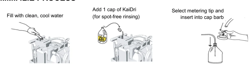
Set-up row: a hand pouring clean water into the top of the machine, a KaiDri bottle with a cap being added to the machine, and a hand fitting a metering tip with tubing into the cap barb of a bottle

Inject

Chemicals

Fan Spray

LOW Pressure Mode

Fan Spray
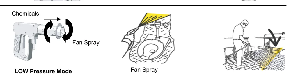
Inject row: a spray gun in low pressure mode with the fan spray nozzle marked by rotating arrows, a hand spraying chemicals in a fan spray onto a toilet bowl, and a worker applying solution to a tiled floor with an arrow pointing down

Manual Brush

Manually brush heavily soiled areas
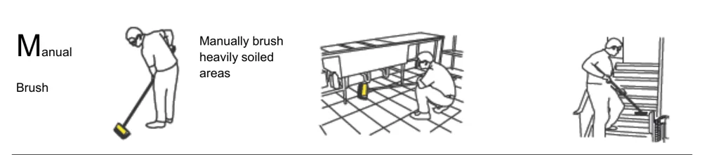
Manual Brush row: a worker using a long-handled brush, a worker crouching to brush under a bench area, and a worker brushing stairs

Pressure wash and rinse

Fresh Water

Fan

HIGH Pressure Mode
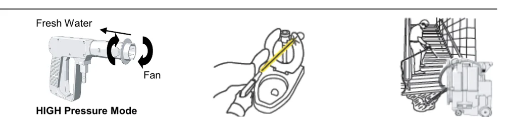
Pressure wash and rinse row: a spray gun in high pressure mode with fresh water and fan nozzle arrows, a hand rinsing a toilet with the spray wand, and a worker rinsing stairs next to the machine

Loop

Hook

Adjust last loop (if needed)
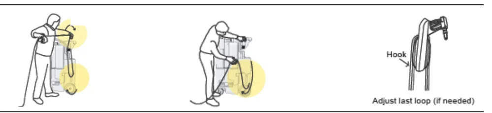
Loop row: a worker coiling the hose into loops beside the machine, a worker placing the hose loops onto the machine, and a hose hung on a hook with a note to adjust the last loop if needed

Extract

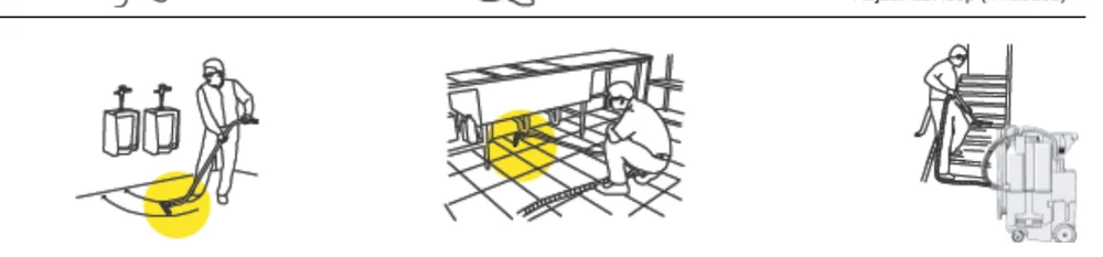
Extract row: a worker using a vacuum tool on the floor near urinals, a worker extracting under a bench, and a worker extracting on stairs next to the machine
Source: Kaivac 1200 Series Operator Manual KV1200_Manual_12-02-2016 Rev. 12-2016, page 11, used with permission. SES ref PF-3TZ6-BNYD‌‌​⁠​‍​‌‍​⁠​‍⁠​​​‌‌‍​​​​​​‍⁠​​​‌​⁠​​​​⁠⁠‌​‍‍​⁠‍​‍‌‍‍‍⁠‌​‌⁠‍‌
1200 Series KV1200_Manual_12-02-2016 (12-2016)Page 11 of 33
3.0 MAINTENANCE

3.1 MACHINE MAINTENANCE

In short This section lists what to check or do for each part of the machine, such as the floor squeegee, spray gun, hoses, tanks, electrical system, vacuum wand and HEPA filter. The machine must be unplugged before the electric cover assembly is lifted.‌‌​⁠​‍​‌‍​⁠​‍⁠​​​‌‌‍​​​​​​⁠​​​​‌​⁠​​​‍⁠​‍⁠⁠​​​‌‍​⁠‍‌⁠‌⁠‍​‌‌‍
CAUTION Always make sure machine is unplugged before lifting electric cover assembly
ItemProcedure
Floor Squeegee
  • Check condition of squeegee blades and wheels on the floor tool.
  • Rough floor surfaces will cause the blades and wheels to wear out more quickly. Replace as necessary
Spray Gun
  • Check spray pattern. If spray pattern will not pinpoint, clean orifice by removing it with an Allen wrench and flushing. Replace if needed.
  • If nozzle becomes difficult to move from high to low pressure lubricate nozzle with lithium grease.
Pressure Hose
  • Wipe clean after each use.
  • Check for cuts or frays in the hose jacket, particularly at the end of the fittings. Replace hose if cuts are found
Water Tank
  • Check condition of filter in water tank. Clean as needed.
  • Empty the water tank to prevent mildew and bacteria growth. Empty tank by dipping the vacuum hose into the water tank and transferring the water to the vacuum tank.
Vacuum Tank
  • Empty and flush vacuum tank.
  • Clean and disinfect.
  • Check the float shutoff screen to be sure it is not plugged up. A plugged filter screen restricts airflow and results in reduced suction.
Leaks
  • Be alert for leaks around hoses, fittings, spray wand, tanks or elsewhere.
  • Discontinue use until leaks are repaired
Electrical System
  • The ground fault circuit interrupter (GFCI) must be tested before each use.
  • Electric cord must be inspected for tears or cuts in the insulation.
Vacuum Wand
  • Use a wire brush or coarse brush with acid cleaner or other to remove residue from threads on the coupling and coupling nut. Apply grease when done.
HEPA Filter
  • Replace every 3-6 months depending on use
Source: Kaivac 1200 Series Operator Manual KV1200_Manual_12-02-2016 Rev. 12-2016, page 12, used with permission. SES ref PF-SOYZ-IQ4N‌‌​⁠​‍​‌‍​⁠​‍⁠​​​‌‌‍​​​​​​⁠​​​​‌​⁠​​​‍⁠​‍⁠⁠​​​‌‍​⁠‍‌⁠‌⁠‍​‌‌‍
1200 Series KV1200_Manual_12-02-2016 (12-2016)Page 12 of 33
3.0 MAINTENANCE

3.2 BLACK BOX REMOVAL INSTRUCTIONS

In short This section shows how to take the black box off the machine in four photo steps. Remove all hoses, cords and tools first, then remove the four wingbolts, tilt the tanks upright and disconnect the water and return lines.‌‌​⁠​‍​‌‍​⁠​‍⁠​​​‌‌‍​​​​​​⁠‌​​​‌​⁠​​⁠‍⁠‌‌⁠‍‍⁠‌​​​‌⁠​​‌⁠‌​‌⁠​
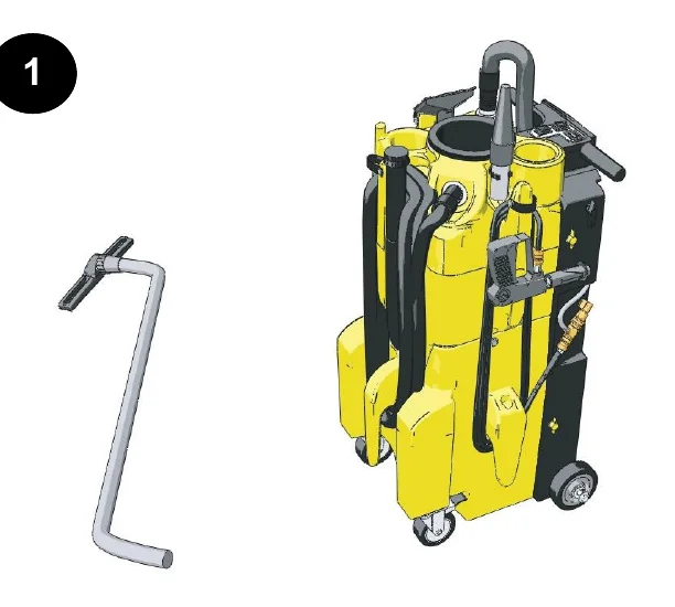
Step 1: a wand tool with a bent tube shown beside the upright yellow machine with its hoses and cords, which are to be removed before black box removal
1

Remove all hoses, cords, and tools prior to black box removal.‌‌​⁠​‍​‌‍​⁠​‍⁠​​​‌‌‍​​​​​​⁠‌​​​‌​⁠​​⁠‍⁠‌‌⁠‍‍⁠‌​​​‌⁠​​‌⁠‌​‌⁠​

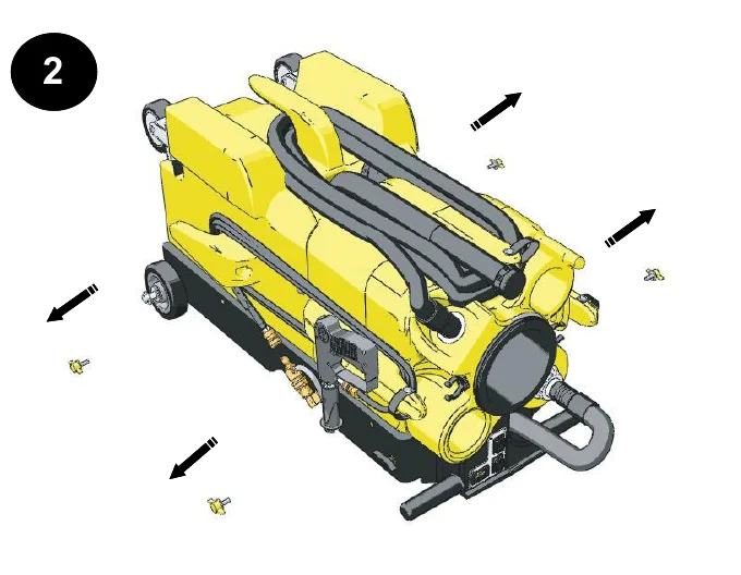
Step 2: the machine lying on its back with four arrows pointing away from the four yellow wingbolts being removed
2

Laying the machine on its back remove the four yellow wingbolts as shown above
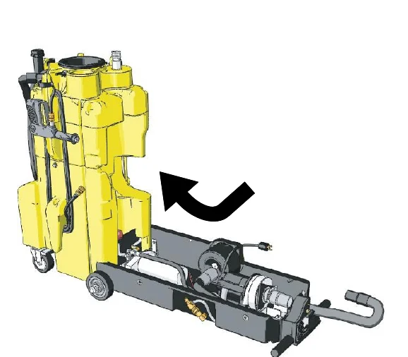
Step 3: the yellow tanks tilted upward to stand upright, with a curved arrow showing the tilt direction and the black box lying flat on the floor
3

Placing your foot on one of the two handles, tilt the yellow tanks upward until standing upright
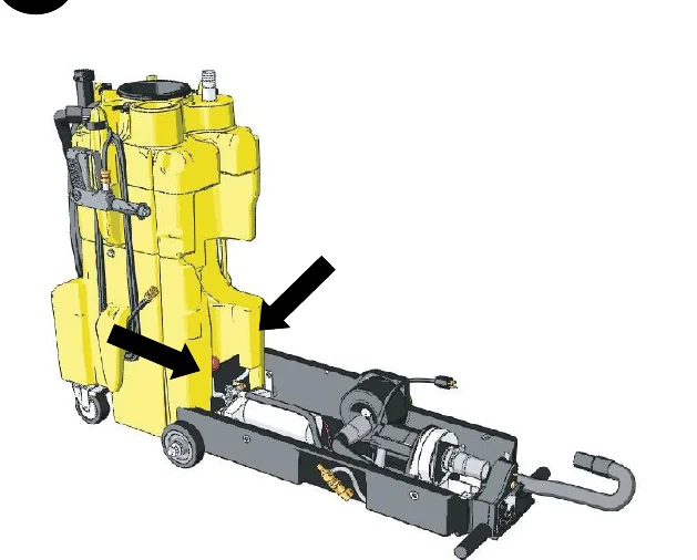
Step 4: the yellow tanks upright with two arrows pointing at the water line and return line behind the black box
4

Locate and disconnect the water line and return line behind the black box on the machine

Source: Kaivac 1200 Series Operator Manual KV1200_Manual_12-02-2016 Rev. 12-2016, page 13, used with permission. SES ref PF-2ZY5-HE4O‌‌​⁠​‍​‌‍​⁠​‍⁠​​​‌‌‍​​​​​​⁠‌​​​‌​⁠​​⁠‍⁠‌‌⁠‍‍⁠‌​​​‌⁠​​‌⁠‌​‌⁠​
1200 Series KV1200_Manual_12-02-2016 (12-2016)Page 13 of 33
3.0 MAINTENANCE

3.3 TROUBLESHOOTING

In short This table lists problems by area (electrical, vacuum system, blow dry system) with their possible causes and solutions. Make sure the machine is unplugged before lifting the electric cover assembly.‌‌​⁠​‍​‌‍​⁠​‍⁠​​​‌‌‍​​​​​​⁠‍​​​‌​⁠​​‌‌​⁠‍​​‍‌⁠​⁠‍‌‍‌‍‌⁠⁠​​​‌
CAUTION Always make sure machine’s unplugged before lifting electric cover assembly
AreaProblemPossible CauseSolution
ElectricalNo Power to pump or vac motorMachine not plugged inPlug machine in
Switch not “on’Check switches for “on”
GFCI trippedTest and reset GFCI
Building circuit overloadedCheck and reset circuit
Switch wires looseDisconnect power and check for loose wire
Connections looseDisconnect Power and check for loose wire under panel
Electrical burning smellVac motor brushes wornRemove vac motor and repair
Vac motor hung upRelease pressure on hose and jog vac switch, or replace
Pump motor hung upRelease pressure on hose and jog pump switch, or replace
Vacuum SystemNo / Weak vacuumVac tank fullEmpty vac tank
Squeegee blades or wheels wornReplace wheels or blades and check periodically
Float shutoff screen dirtySpray off float screen to clean
Float ball stuckTap float and release/clean
Damaged hoseCut and repair/replace
Dump hose plug missingContact dealer and replace
Access lid not tightTighten lid hand tight
Vacuum hose pluggedFlush hose to remove debris
Too much liquid in vac hoseAllow air in when vacuuming
Vac hose still wrappedUnwrap vac hose fully
Exhaust pluggedRemove HEPA filter and clean
Leak in vac tankIf repairable, clean and dry affected area and seal with silicone
HEPA Filter cloggedRemove HEPA filter and clean
Moisture from exhaustVac tank fullDump vac tank
Float shutoff missingReplace
Excessive foam in vac tankUse defoamer
Blow Dry SystemNo air flowHose disconnectedReconnect hose
Moisture from nozzleWater in blow hoseDry blow line
Suction, not blow actionVacuum hose connected to vac tankReconnect to vac motor exhaust hose
Source: Kaivac 1200 Series Operator Manual KV1200_Manual_12-02-2016 Rev. 12-2016, page 14, used with permission. SES ref PF-4D7H-E4ZT‌‌​⁠​‍​‌‍​⁠​‍⁠​​​‌‌‍​​​​​​⁠‍​​​‌​⁠​​‌‌​⁠‍​​‍‌⁠​⁠‍‌‍‌‍‌⁠⁠​​​‌
1200 Series KV1200_Manual_12-02-2016 (12-2016)Page 14 of 33
3.0 MAINTENANCE
AreaProblemPossible CauseSolution
High Pressure SystemNo water from pump or low pressureOut of WaterFill water tank
Gun nozzle pluggedRemove orifice with Allen wrench and clean
Air in pump (vapor lock)Use power prime technique
Gun orifice missingReplace orifice
Water tank filter pluggedClean tank and filter
In - line bowl filter pluggedRemove filter cover and clean
Bowl filter lid looseGently tighten bowl cover
Pressure hose damagedRepair or replace
Quick disconnect leakingTighten or replace
Injector pluggedRemove safety cap from chemical and blow small amounts of compressed air into line
Pulse hose damagedRepair or replace
Regulator failedReplace
Hose kinkedUnkink and check for damage
Seals in pump need replacedRemove and replace seals
Bad fan pattern or pinpoint pattern on gunDebris in nozzleRemove orifice with Allen wrench and clean
Orifice damagedRemove and replace
Chemical Injection SystemNo chemical flowOut of chemicalRefill chemical
Safety cap not secureCheck safety cap / tighten
Chemical valve “off”Check on / off valve
Safety cap pluggedReplace cap
Spray gun in wrong modeMake sure gun nozzle is pulled out away from gun chemical mode
Metering tip pluggedCheck metering tip for clog
Injector pluggedRemove safety cap from chemical and blow small amounts of compressed air into line
Air entering systemCheck for air entering system around chemical lines or injector
Injector installed backwardsIf fluttering or pulsing sound can be heard while spraying or when machine is running it is possible that your injector is in backwards. Remove and reinstall
Kink in Chemical lineReplace Chemical line
Source: Kaivac 1200 Series Operator Manual KV1200_Manual_12-02-2016 Rev. 12-2016, page 15, used with permission. SES ref PF-L7HB-2YW4‌‌​⁠​‍​‌‍​⁠​‍⁠​​​‌‌‍​​​​​​⁠⁠​​​‌​⁠​​‌‌⁠⁠​⁠‍‌‌⁠​⁠⁠‌⁠‌​​‍‌‌⁠‌​
1200 Series KV1200_Manual_12-02-2016 (12-2016)Page 15 of 33
3.0 MAINTENANCE
AreaProblemPossible CauseSolution
Chemical Injection System continuedNot enough chemicalMetering tip pluggedRemove and clean
Wrong metering tipCheck and replace per chart
Chemical line blows off safety capDebris in injectorRemove safety cap from chemical and blow small amounts of compressed air into line
Water back flows into chemical bottleBad seat on injector check valveCheck injector o - ring or replace
Bad safety capReplace safety cap
Dump SystemDump hose will not empty tankDump hose cap not removedRemove cap
Clog in bottom of tankTip dump contents, remove debris
Dump hose leaksHose cutIf leak is less than 4" from tank side, cut and reattach, or replace
Clamp looseTighten hose clamp
Dump cap missingReplace cap
Wheels and CastersWheels won’t roll, or they rubFlat tiresInflate tires to 30 p. s. i.
Debris wrapped around axleCheck for debris on axle
Bearings tightGrease bearings
Wheels too loose on axleRemove wheel, add washers to take up slack
Bearings falling outReplace bearing assembly
Squeegee HeadFloor streaksWorn blades or wheelsReplace wheels and / or blades
Squeegee head doesn’t easily rotate when installed on wandBrass ring on wand not in grooveLoosen coupling nut and re-position head on groove
Coupling nut too tightLoosen 1 / 2 turn
Head won’t stay on wandCoupling nut crackedReplace
Brass ring wornReplace
Premature blade wearSqueegee wheels wornCheck wheels for wear / replace
Sucks to the floor too tightlySqueegee wheels wornCheck wheels for wear / replace
Source: Kaivac 1200 Series Operator Manual KV1200_Manual_12-02-2016 Rev. 12-2016, page 16, used with permission. SES ref PF-SVUT-ZL4F‌‌​⁠​‍​‌‍​⁠​‍⁠​​​‌‌‍​​​​​‌​​​​​‌​⁠​​‌‌⁠‍⁠‍​‍​‌‍⁠‌‌​⁠⁠‌​‍‍⁠‌​
1200 Series KV1200_Manual_12-02-2016 (12-2016)Page 16 of 33
3.0 MAINTENANCE

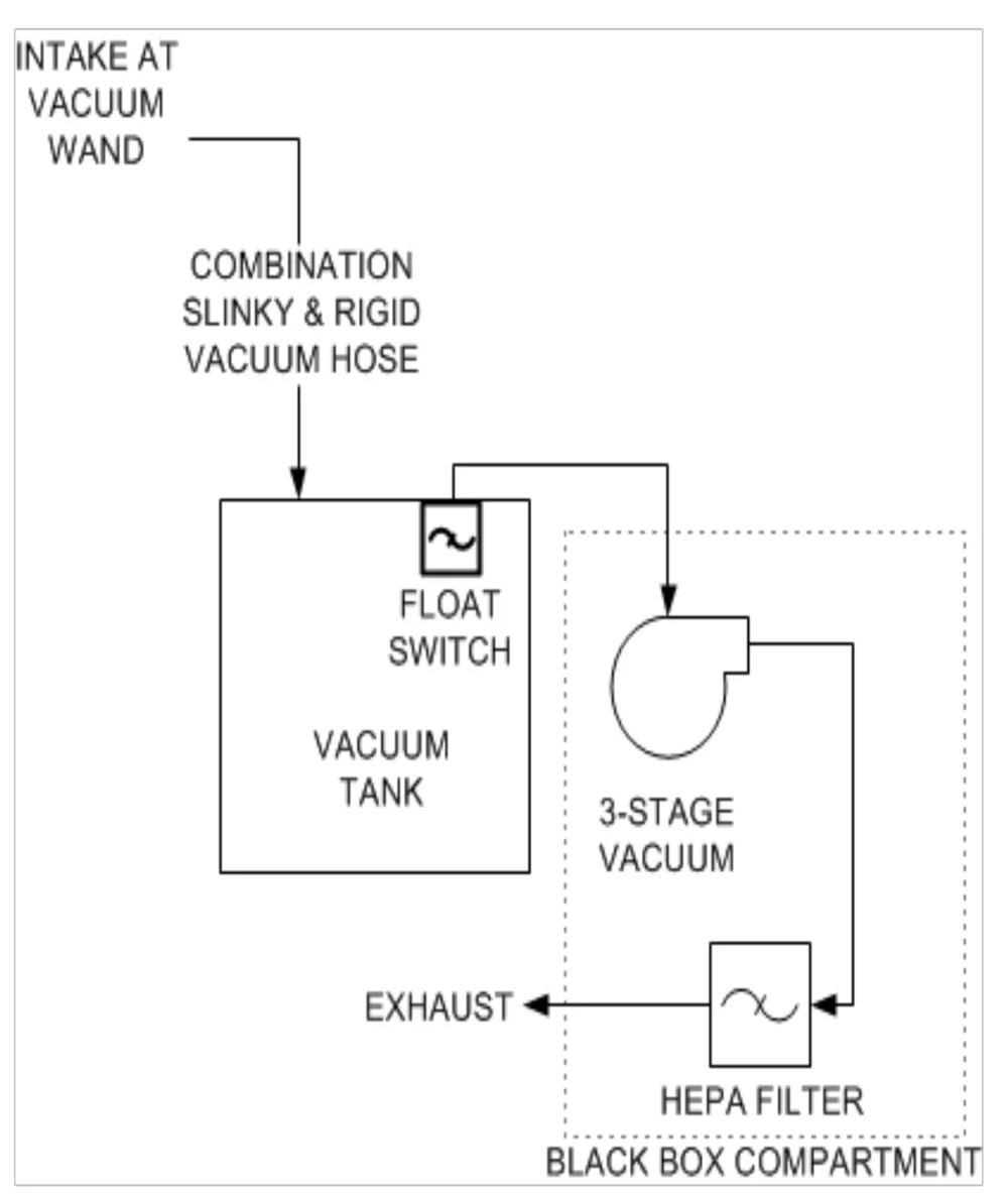
3.4 VACUUM DIAGRAM

In short This section shows how air and recovered liquid travel through the vacuum system. The path runs from the vacuum wand through the hose to the vacuum tank, then through the 3-stage vacuum and the HEPA filter to the exhaust.‌‌​⁠​‍​‌‍​⁠​‍⁠​​​‌‌‍​​​​​‌​‌​​​‌​⁠​​⁠​⁠⁠‍​​‌‌⁠⁠​⁠‌‌‍⁠‍‍⁠⁠‍‌‍
Vacuum system flow diagram. Intake at vacuum wand leads through the combination slinky and rigid vacuum hose into the vacuum tank, which has a float switch at its top. Air then goes to the 3-stage vacuum in the black box compartment, through the HEPA filter, and out the exhaust.
Source: Kaivac 1200 Series Operator Manual KV1200_Manual_12-02-2016 Rev. 12-2016, page 17, used with permission. SES ref PF-K4DT-WO6M‌‌​⁠​‍​‌‍​⁠​‍⁠​​​‌‌‍​​​​​‌​‌​​​‌​⁠​​⁠​⁠⁠‍​​‌‌⁠⁠​⁠‌‌‍⁠‍‍⁠⁠‍‌‍
1200 Series KV1200_Manual_12-02-2016 (12-2016)Page 17 of 33
3.0 MAINTENANCE

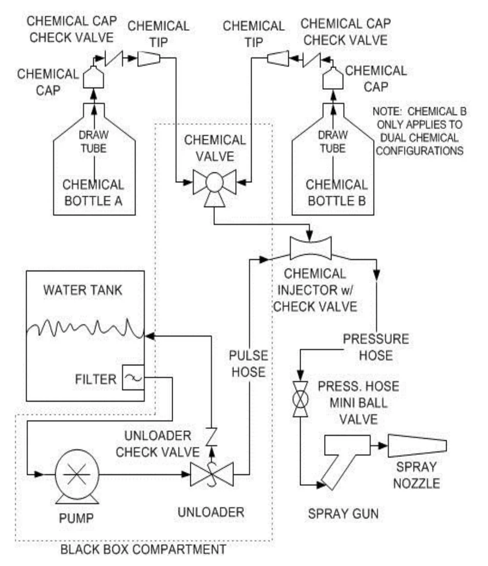
3.4 PUMP DIAGRAM

In short This page shows a flow diagram of the pump system. It traces how water from the tank and chemical from the bottles reach the spray gun and spray nozzle.‌‌​⁠​‍​‌‍​⁠​‍⁠​​​‌‌‍​​​​​‌​‍​​​‌​⁠​​​⁠‌‌⁠‍​‌‌⁠⁠‌​⁠⁠⁠‍‌​‍‍‍​‌
Pump system flow diagram. Chemical bottle A and chemical bottle B each have a draw tube, chemical cap, chemical cap check valve and chemical tip, and feed a chemical valve. A note says chemical B only applies to dual chemical configurations. The chemical valve feeds a chemical injector with check valve. The water tank, through a filter, supplies the pump, then the unloader. The unloader sends a pulse hose line to the injector and returns through the unloader check valve to the water tank. The pump, unloader and unloader check valve sit in the black box compartment. From the injector a pressure hose runs through the pressure hose mini ball valve to the spray gun and spray nozzle.
Source: Kaivac 1200 Series Operator Manual KV1200_Manual_12-02-2016 Rev. 12-2016, page 18, used with permission. SES ref PF-4AIU-HU64‌‌​⁠​‍​‌‍​⁠​‍⁠​​​‌‌‍​​​​​‌​‍​​​‌​⁠​​​⁠‌‌⁠‍​‌‌⁠⁠‌​⁠⁠⁠‍‌​‍‍‍​‌
1200 Series KV1200_Manual_12-02-2016 (12-2016)Page 18 of 33
3.0 MAINTENANCE

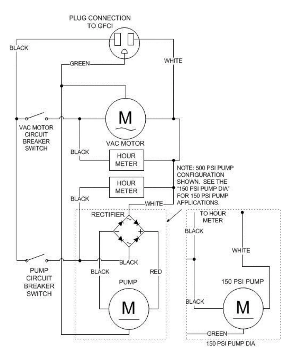
3.4 ELECTRICAL DIAGRAM

In short This page shows the wiring diagram for the machine, from the plug connection to the GFCI through the vac motor, pump, hour meters and circuit breaker switches. The note on the diagram says the 500 PSI pump configuration is shown and a separate 150 PSI pump diagram applies to 150 PSI pump applications.‌‌​⁠​‍​‌‍​⁠​‍⁠​​​‌‌‍​​​​​‌​⁠​​​‌​⁠​​‍‌‍‍⁠⁠​‍⁠⁠​‌‌⁠‌⁠‍⁠⁠​​‌⁠​
Electrical wiring diagram. A plug connection to GFCI feeds black, white and green wires. The black wire goes through the vac motor circuit breaker switch to the vac motor and, through the pump circuit breaker switch, to a rectifier and the pump motor, with black and red leads. Two hour meters are shown, one on the vac motor circuit and one on the pump circuit. A dotted box at right shows the 150 PSI pump diagram with black, white and green wires and a connection to the hour meter. A note reads: 500 PSI pump configuration shown. See the 150 PSI PUMP DIA for 150 PSI pump applications.
Source: Kaivac 1200 Series Operator Manual KV1200_Manual_12-02-2016 Rev. 12-2016, page 19, used with permission. SES ref PF-56NZ-6LLV‌‌​⁠​‍​‌‍​⁠​‍⁠​​​‌‌‍​​​​​‌​⁠​​​‌​⁠​​‍‌‍‍⁠⁠​‍⁠⁠​‌‌⁠‌⁠‍⁠⁠​​‌⁠​
1200 Series KV1200_Manual_12-02-2016 (12-2016)Page 19 of 33
3.0 MAINTENANCE

3.4 MACHINE DIAGRAMS

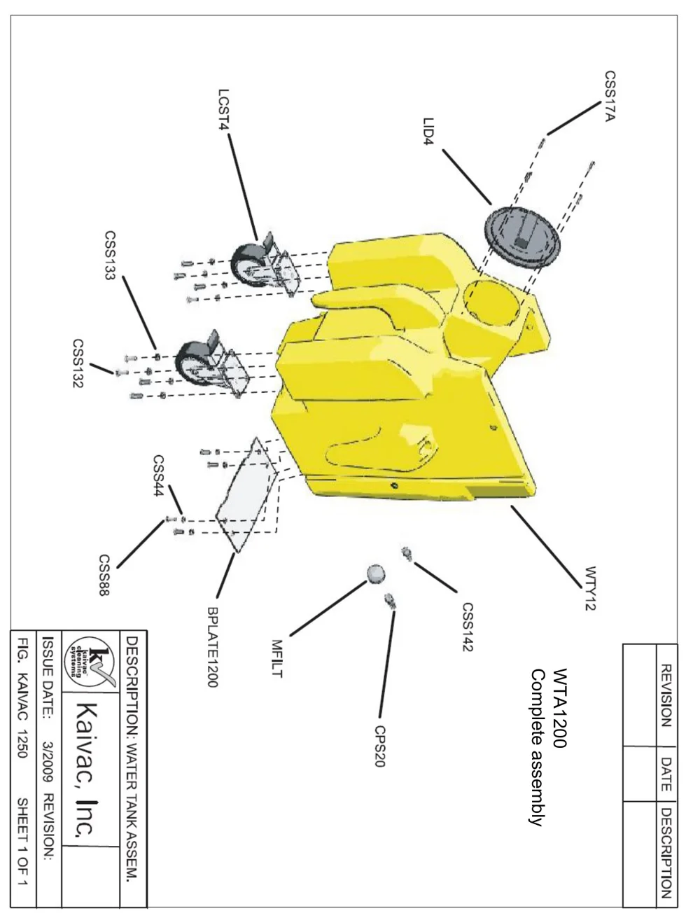
In short This section shows exploded diagrams of the machine's assemblies. This page shows the complete water tank assembly, WTA1200, with the part code for each component.‌‌​⁠​‍​‌‍​⁠​‍⁠​​​‌‌‍​​​​​‌‌​​​​‌​⁠​​‌‌‍​​‍‌⁠‍⁠‍​⁠‍‍‌​‍‍​‍​‍‌
Exploded drawing of the yellow water tank assembly WTA1200, shown rotated sideways, with labeled parts: LCST4 and CSS132/CSS133 for the casters and their hardware, LID4 and CSS17A for the lid and its screws, CSS44 and CSS88 for the hardware at the plate, BPLATE1200 for the plate, MFILT, CPS20 and CSS142 for the filter and fittings, and WTY12 for the tank. A Kaivac title block at the lower left reads Description: Water Tank Assem., Issue date 3/2009, Fig. Kaivac 1250, Sheet 1 of 1.
WTA1200 Complete assembly

WTA1200 Complete assembly‌‌​⁠​‍​‌‍​⁠​‍⁠​​​‌‌‍​​​​​‌‌​​​​‌​⁠​​‌‌‍​​‍‌⁠‍⁠‍​⁠‍‍‌​‍‍​‍​‍‌

Source: Kaivac 1200 Series Operator Manual KV1200_Manual_12-02-2016 Rev. 12-2016, page 20, used with permission. SES ref PF-XHC5-7BBD‌‌​⁠​‍​‌‍​⁠​‍⁠​​​‌‌‍​​​​​‌‌​​​​‌​⁠​​‌‌‍​​‍‌⁠‍⁠‍​⁠‍‍‌​‍‍​‍​‍‌
1200 Series KV1200_Manual_12-02-2016 (12-2016)Page 20 of 33
3.0 MAINTENANCE

3.4 MACHINE DIAGRAMS

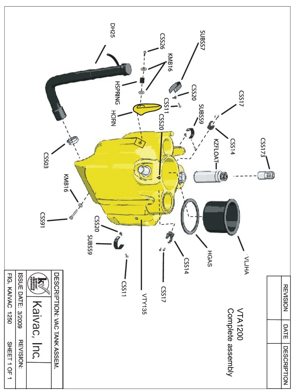
In short This section shows the machine diagrams. This page shows the exploded view of the VTA1200 vac tank complete assembly with each part labeled by its part code.‌‌​⁠​‍​‌‍​⁠​‍⁠​​​‌‌‍​​​​​‌‌‌​​​‌​⁠​​​​‌⁠‍‌‌‍⁠​​‍‌⁠‌‌⁠‍‌⁠⁠‍‌⁠
Exploded view of the yellow vac tank assembly (VTA1200), turned sideways on the page, with callout codes for each part: DH25 hose, CSS26, KMB16, HSPRING, HORN, CSS11, CSS20, SUBSS7, SUBSS9, CSS17, CSS14, KZFLOAT, CSS173, CSS03, CSS91, HGAS gasket, VLJHA, and VTY135 tank. A title block reads Kaivac, Inc., Fig. KAIVAC 1250, Description: Vac Tank Assem., Issue date 3/2009.
VTA1200 Complete assembly

VTA1200
Complete assembly‌‌​⁠​‍​‌‍​⁠​‍⁠​​​‌‌‍​​​​​‌‌‌​​​‌​⁠​​​​‌⁠‍‌‌‍⁠​​‍‌⁠‌‌⁠‍‌⁠⁠‍‌⁠

Source: Kaivac 1200 Series Operator Manual KV1200_Manual_12-02-2016 Rev. 12-2016, page 21, used with permission. SES ref PF-XFJZ-QRPK‌‌​⁠​‍​‌‍​⁠​‍⁠​​​‌‌‍​​​​​‌‌‌​​​‌​⁠​​​​‌⁠‍‌‌‍⁠​​‍‌⁠‌‌⁠‍‌⁠⁠‍‌⁠
1200 Series KV1200_Manual_12-02-2016 (12-2016)Page 21 of 33
MAINTENANCE

3.4 MACHINE DIAGRAMS

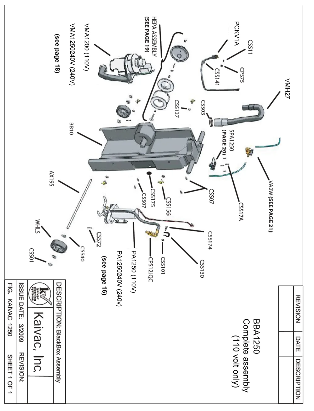
In short This section shows an exploded diagram of the BBA1250 complete assembly (110 volt only), with part numbers marked and references to other pages for the vacuum motor, pump and related assemblies.‌‌​⁠​‍​‌‍​⁠​‍⁠​​​‌‌‍​​​​​‌‌‍​​​‌​⁠​​⁠⁠⁠⁠​‍‌​⁠⁠‌‌‍⁠‌‍​⁠​‍‌‍‌​
Exploded diagram of the BlackBox assembly, rotated sideways on the page, showing the main housing BB10, vacuum motor VMA1200 (110V) or VMA1250240V (240V), HEPA assembly, power cord PCKV1A, vacuum hose VMH27, pump assembly PA1250 (110V) or PA1250240V (240V), axle AX195, wheel WHL5, solenoid valve VA2W, SPA1250 and fasteners labeled CSS01 to CSS175, with page references to pages 16, 18, 19, 20 and 21. A Kaivac, Inc. title block at the bottom reads BlackBox Assembly, Fig. KAIVAC 1250, sheet 1 of 1, issue date 3/2009.
BBA1250 Complete assembly (110 volt only)
Source: Kaivac 1200 Series Operator Manual KV1200_Manual_12-02-2016 Rev. 12-2016, page 22, used with permission. SES ref PF-CT6K-WJZ3‌‌​⁠​‍​‌‍​⁠​‍⁠​​​‌‌‍​​​​​‌‌‍​​​‌​⁠​​⁠⁠⁠⁠​‍‌​⁠⁠‌‌‍⁠‌‍​⁠​‍‌‍‌​
1200 Series KV1200_Manual_12-02-2016 (12-2016)Page 22 of 33
3.0 MAINTENANCE

3.4 MACHINE DIAGRAMS

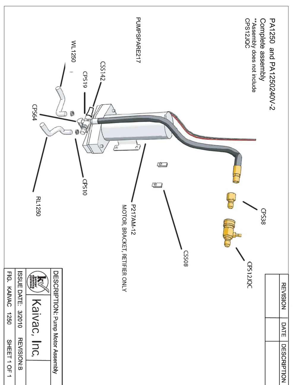
In short This section shows the machine diagrams. This page has the exploded drawing of the pump motor assembly, with part codes labeled on each component.‌‌​⁠​‍​‌‍​⁠​‍⁠​​​‌‌‍​​​​​‌‌⁠​​​‌​⁠​​‍‌​⁠‍⁠​‌​⁠⁠⁠​‌​⁠⁠‌‌‍⁠‍⁠‌
Exploded drawing of the pump motor assembly, drawn rotated sideways, with part codes: PUMPSPARE217, PA1250 and PA1250240V-2 complete assembly (assembly does not include CPS12JQC), WL1250, CSS142, CPS19, CPS64, CPS10, RL1250, P217AM-12 (motor, bracket, rectifier only), CSS08, CPS38 and CPS12JQC. It shows the pump motor with bracket, the cable and brass fittings, the hoses and small hardware, with a Kaivac title block at the lower left
DESCRIPTION: Pump Motor Assembly, FIG. KAIVAC 1250, ISSUE DATE: 3/2010, REVISION: B, SHEET 1 OF 1
Source: Kaivac 1200 Series Operator Manual KV1200_Manual_12-02-2016 Rev. 12-2016, page 23, used with permission. SES ref PF-4OSJ-6WBI‌‌​⁠​‍​‌‍​⁠​‍⁠​​​‌‌‍​​​​​‌‌⁠​​​‌​⁠​​‍‌​⁠‍⁠​‌​⁠⁠⁠​‌​⁠⁠‌‌‍⁠‍⁠‌
1200 Series KV1200_Manual_12-02-2016 (12-2016)Page 23 of 33
MAINTENANCE

3.4 MACHINE DIAGRAMS

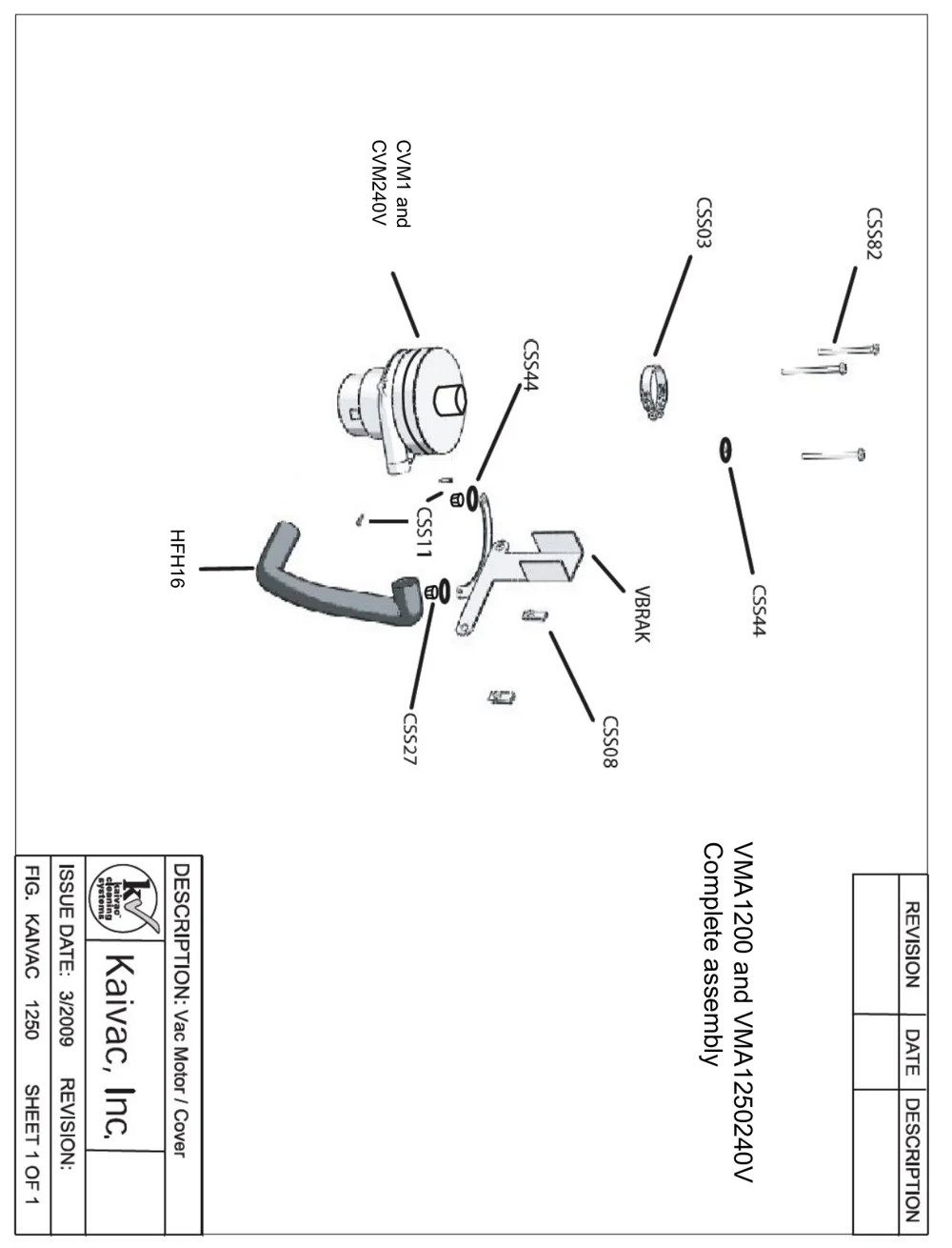
In short This section holds the exploded machine diagrams. This page shows the vac motor and cover complete assembly for the VMA1200 and VMA1250240V, with each part labeled by its part code.‌‌​⁠​‍​‌‍​⁠​‍⁠​​​‌‌‍​​​​​‌‍​​​​‌​⁠​​‌‌‍‍‌‍⁠‍‍‌‍​​‍‍‌​‌‍‌‌​‍‍
Exploded drawing of the vac motor and cover complete assembly, rotated sideways on the page, with the vac motor, hose, clamp, bracket, screws, and O-rings labeled CVM1 and CVM240V, HFH16, CSS03, CSS82, CSS44, CSS11, CSS27, CSS08 and VBRAK; a title block reads Kaivac, Inc., Description: Vac Motor / Cover, Fig. Kaivac 1250, Sheet 1 of 1
VMA1200 and VMA1250240V Complete assembly
Source: Kaivac 1200 Series Operator Manual KV1200_Manual_12-02-2016 Rev. 12-2016, page 24, used with permission. SES ref PF-NHTJ-MBSD‌‌​⁠​‍​‌‍​⁠​‍⁠​​​‌‌‍​​​​​‌‍​​​​‌​⁠​​‌‌‍‍‌‍⁠‍‍‌‍​​‍‍‌​‌‍‌‌​‍‍
1200 Series KV1200_Manual_12-02-2016 (12-2016)Page 24 of 33
3.0 MAINTENANCE

3.4 MACHINE DIAGRAMS

HEPA HOUSING ASSEMBLY (HEPAHA2)
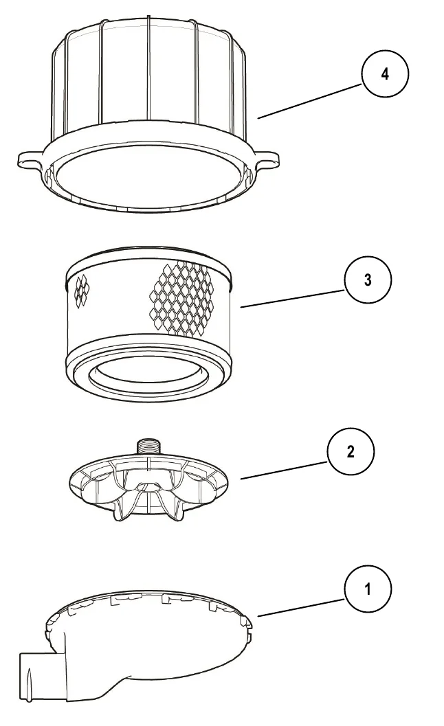
In short This page shows an exploded diagram of the HEPA housing assembly (HEPAHA2) with its four numbered parts. The table beside it lists each part number and description.‌‌​⁠​‍​‌‍​⁠​‍⁠​​​‌‌‍​​​​​‌‍‌​​​‌​⁠​​​‍‌‍​‍⁠‍‌⁠⁠‍‍⁠‌‌‌⁠⁠‌‍‌‍‍
Exploded view of the HEPA housing assembly with four parts stacked top to bottom: callout 4 the large ribbed filter housing with a flanged base, callout 3 the cylindrical HEPA filter with a diamond-pattern section, callout 2 the filter keeper with a threaded stud on top, and callout 1 the cover with an outlet spout at the left.
#PART NO.PART DESCRIPTION
1HCOVERHEPA COVER
2FKEEP2HEPA FILTER KEEPER
3HEPAHEPA FILTER
4HEPAH2HEPA FILTER HOUSING
Source: Kaivac 1200 Series Operator Manual KV1200_Manual_12-02-2016 Rev. 12-2016, page 25, used with permission. SES ref PF-AEWM-FURY‌‌​⁠​‍​‌‍​⁠​‍⁠​​​‌‌‍​​​​​‌‍‌​​​‌​⁠​​​‍‌‍​‍⁠‍‌⁠⁠‍‍⁠‌‌‌⁠⁠‌‍‌‍‍
1200 Series KV1200_Manual_12-02-2016 (12-2016)Page 25 of 33
3.0 MAINTENANCE

3.4 MACHINE DIAGRAMS

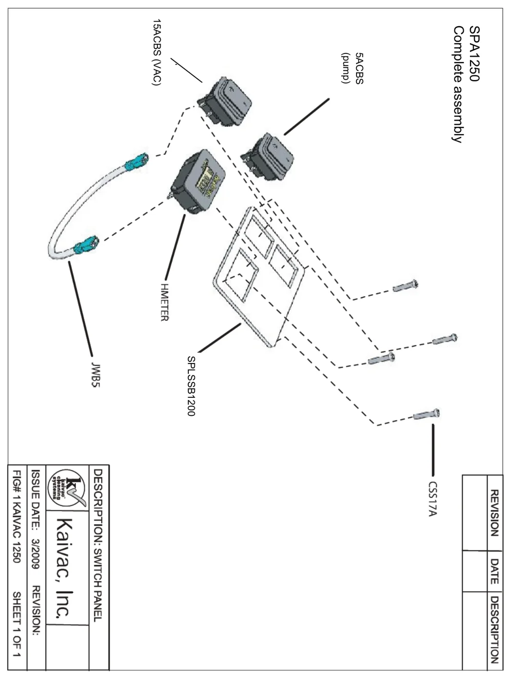
In short This section contains exploded parts diagrams of the machine. This page shows the switch panel assembly SPA1250 with its switches, hour meter, jumper cable, panel and screws.‌‌​⁠​‍​‌‍​⁠​‍⁠​​​‌‌‍​​​​​‌‍‍​​​‌​⁠​​‍‍​⁠‍⁠‍​⁠‌​‍‌‌​‌⁠⁠⁠⁠⁠​​‌
Exploded drawing of the switch panel, rotated sideways on the page, with dashed lines showing how parts fit together. Callouts: 15ACBS (VAC) switch, 5ACBS (pump) switch, HMETER hour meter, JWB5 jumper cable with blue connector ends, SPLSSB1200 switch panel plate, and three CSS17A screws. Labeled SPA1250 Complete assembly. The title block reads Kaivac, Inc., Description: Switch Panel, Issue date 3/2009, FIG# 1 KAIVAC 1250, Sheet 1 of 1.
SPA1250 Complete assembly
Source: Kaivac 1200 Series Operator Manual KV1200_Manual_12-02-2016 Rev. 12-2016, page 26, used with permission. SES ref PF-SZA6-BULW‌‌​⁠​‍​‌‍​⁠​‍⁠​​​‌‌‍​​​​​‌‍‍​​​‌​⁠​​‍‍​⁠‍⁠‍​⁠‌​‍‌‌​‌⁠⁠⁠⁠⁠​​‌
1200 Series KV1200_Manual_12-02-2016 (12-2016)Page 26 of 33
3.0 MAINTENANCE

3.4 MACHINE DIAGRAMS

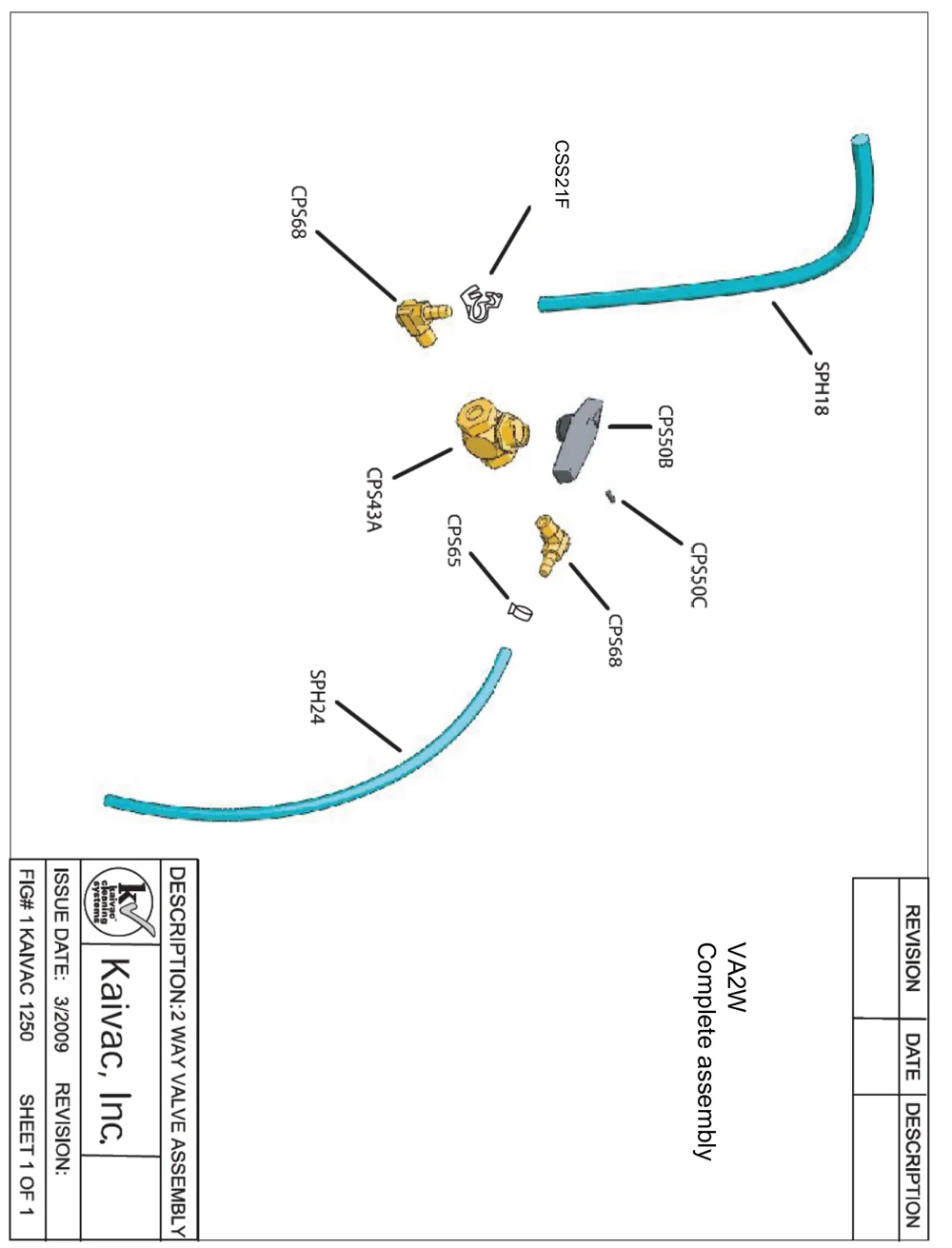
In short This section shows parts diagrams of the machine. This page shows the complete 2 way valve assembly (VA2W) with its part numbers labeled.‌‌​⁠​‍​‌‍​⁠​‍⁠​​​‌‌‍​​​​​‌‍⁠​​​‌​⁠​​‍​​‍⁠​⁠⁠​‌​‍‌​‌​‍⁠‍​‌‌‌‍
Exploded parts drawing of the 2 way valve assembly, turned sideways on the page, with part labels CSS21F, CPS68 (two), SPH18, CPS50B, CPS50C, CPS43A, CPS65 and SPH24 pointing to the clip, two brass fittings, a green hose, the valve handle, a small pin, the brass valve body, a small clamp and a blue hose. A title block reads: Description 2 way valve assembly, Fig# 1 Kaivac 1250, issue date 3/2009, sheet 1 of 1, with VA2W Complete assembly.
FIG# 1 KAIVAC 1250 - 2 WAY VALVE ASSEMBLY, VA2W Complete assembly

VA2W
Complete assembly‌‌​⁠​‍​‌‍​⁠​‍⁠​​​‌‌‍​​​​​‌‍⁠​​​‌​⁠​​‍​​‍⁠​⁠⁠​‌​‍‌​‌​‍⁠‍​‌‌‌‍

Source: Kaivac 1200 Series Operator Manual KV1200_Manual_12-02-2016 Rev. 12-2016, page 27, used with permission. SES ref PF-Z6G5-OBZF‌‌​⁠​‍​‌‍​⁠​‍⁠​​​‌‌‍​​​​​‌‍⁠​​​‌​⁠​​‍​​‍⁠​⁠⁠​‌​‍‌​‌​‍⁠‍​‌‌‌‍
1200 Series KV1200_Manual_12-02-2016 (12-2016)Page 27 of 33
MAINTENANCE

3.4 MACHINE DIAGRAMS

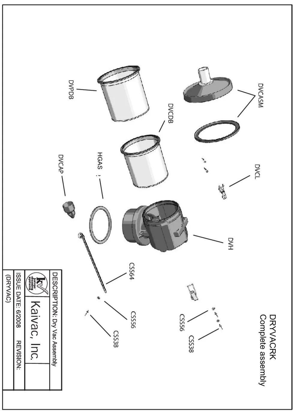
In short This section shows parts diagrams of the machine. This page has the exploded view of the Dry Vac complete assembly, DRYVACRK, with each part labeled by its code.‌‌​⁠​‍​‌‍​⁠​‍⁠​​​‌‌‍​​​​​‌⁠​​​​‌​⁠​​‍‍​‌​⁠⁠​⁠⁠‌⁠‌​‍‌‌‌‍‍‍⁠⁠​
Exploded drawing of the Dry Vac complete assembly, turned sideways on the page, showing the vacuum head and lid assembly, two tank bodies, gasket, cap, latches, a long rod and small fasteners, with part codes DVPDB, DVCDB, DVCASM, DVCAP, HGAS, DVCL, DVH, CSS64, CSS56 and CSS38 pointing to the parts
DRYVACRK Complete assembly
Source: Kaivac 1200 Series Operator Manual KV1200_Manual_12-02-2016 Rev. 12-2016, page 28, used with permission. SES ref PF-COM4-SWNV‌‌​⁠​‍​‌‍​⁠​‍⁠​​​‌‌‍​​​​​‌⁠​​​​‌​⁠​​‍‍​‌​⁠⁠​⁠⁠‌⁠‌​‍‌‌‌‍‍‍⁠⁠​
1200 Series KV1200_Manual_12-02-2016 (12-2016)Page 28 of 33

Kaivac and KaiVac are trademarks of Kaivac, Inc. Southeastern Equipment & Supply is an independent dealer.


Not Sure Which Machine Fits Your Floors?

Talk to a real SES tech about new, demo or certified reconditioned options, parts and service.

© 2026 Southeastern Equipment and Supply, Inc. All Rights Reserved.

Visa Discover AMEX Mastercard